
Related Manuals for CDVI CDV96KP


Summary of Contents for CDVI CDV96KP
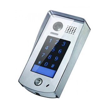
- Page 1 2 -Wire Intercom System CDV96KP User Manual CDV96KP CDV96KP-SF CDV-ENG-96/KP-V2...
-
Page 2: Table Of Contents
Contents 1. Parts and Functions..................... 1 2. Mounting ......................1 3.Terminal Description..................... 2 4. System Wiring and Connections ................. 3 5. Pan,Tilt & Zoom Function ..................7 6. Function Setting Up ..................... 9 7. Power Supply Instructions .................. 17 8. -
Page 3: Parts And Functions
Rain Cover Microphone 93 mm CDV96 KP 2.Mounting CDV96KP Mounting Drill holes in the wall to match the size of Connect the cable correctly screws and attach the rain cover to the wall. Attach the panel to the rain cover Using a screwdriver attach the keypad to the rain cover, see diagram above. -
Page 4: Terminal Description
Placing Name Label Using a screwdriver remove the fixing screw, pull forward the panel and slide in the name plate. 3.Terminal Descriptions • Lock Control Jumper: To select the lock type. • Main Connect Port: To connect the bus line and the electronic locks. -
Page 5: System Wiring And Connections
4.System Wiring and Connections Basic Connection BUS(IM) BUS(DS) L1 L2 PL S+ S- Doorbell Button Switch Electric Lock Connection A fail secure (power applied to unlock) electronic lock device should be used. Note: Electronic lock of Power-on-to-unlock type should be used. The door lock is limited to 12V, and holding current must be less than 250mA. -
Page 6: Door Lock Controlled With Dry Contact
Note: 1.must connect CDV96KP correctly before setting. 2.the parameter will be saved in CDV96KP automatically,so you need only set on one monitor. 3.the above diagram is fit for icon menu series monitors only, to text menu series monitors,please refer to... -
Page 7: Multi Door Stations Connection
Multi Door Stations Connection 4# Camera 3# Camera 2# Camera 1# Camera (Device Address:3) (Device Address:2) (Device Address:1) (Device Address:0) 100~240VAC A B C D DBC4A BUS(IM) BUS(DS) Impedance switch Basic IN-OUT(Daisy Chain) Wiring Mode Code=15 Code=14 Code=0 100~240VAC BUS(IM) BUS(DS) (Device Address:0) - Page 8 With DBC4A Wiring Mode Impedance Code=15 Code=14 OFF ON switch Code=13 Code=12 NOTE: DT47M( monitor s ) used as an example. Code=3 Code=2 Impedance OFF ON switch Code=1 Code=0 100~240VAC Important: When installing multiple monitors a maximum of 4 monitors can be set to show video during the ring time, if more than 4 monitors show video during the call a current overload...
-
Page 9: Pan,Tilt & Zoom Function
5. Pan-tilt & Zoom & Panview Please Note: this function requires the CDV47-MGv2 monitor with zoom function. It is possible to adjust the display view from the CDV96KPv2 door station byusing the 5 direction pad button. When the door station image displayed, move to the desired position by touching on the screen to view the image in zoom mode. - Page 10 1) Touch area 4: zoom to area 4, the lens moves to area 6, and then returns to area 4;(see details below) Note: Touch the screen again to exit the panview mode. 2) Touch area 6: zoom area 6, the lens moves to area 4, and then returns to area 6;(As details below) Note: Touch the screen again to exit the panview mode.
-
Page 11: Function Setting Up
6. Functions Setting Up This section explains the settings for each function,please refer to the following table: Programming mode: Input the master code to enter the programming mode then enter the corresponding setting code to set the function required. Press " " to exit the setting mode. •... - Page 12 Order Setting range Default value Setting code Function Reset all settings 1234 1 ~ 12 digits Sets the master code 1234 Valid keys:0 ~ 9 Sets the key 10 to 99 seconds/ 10 seconds illumination time continually lit Sets the unlock time 01 to 99 seconds 1 seconds Sets the unlock mode...
- Page 13 Each operation is indicated by the lighting up of the different color of digital key and nameplate , and by the sounding of the buzzer. The color of key indicator Input the master code. (Default: [ ] +[#] ) (white) Beep+, Beep 1.Reset all settings 2.Setting the master code...
- Page 14 The color of key indicator Input the master code. (Default: [ ] +[#]) (white) Beep+, Beep 5.Setting the unlock mode 6.Setting operation tone 7.Reset code setting 8. &# function setting (Default 0(opened)) (Default ON) (Default Normal) Input the setting code. Input the setting code.
- Page 15 Input the master code. The color of key indicator (Default: [ ] +[#]) Beep+, Beep (white) 9. Call tone setting 10.Interference resistant 11.IMC volume adjust 12.SPK volume adjust grade setting setting setting (Default enable) (Default 2) (Default:7) (Default:4) Input the setting code. Input the setting code.
- Page 16 Input the master code. The color of key indicator (Default: [ ] +[#]) Beep+, Beep (white) 13. Display scene setting 14.Night light level 15.Device address setting setting (Default 0) (Default 4) (Default:0 ) Input the setting code. Input the setting code. Input the setting code.
- Page 17 (red) (blue) Input the master code. (Default: [ ]+[#] ) Beep+, Beep 16.Setting the code 17.Setting the code 18.Setting the code 19.Setting the code forTemporary1 forTemporary2 for user group1 for user group2 20~59 60~99 Input the setting code. Input the setting code. Input the setting code.
- Page 18 Input the master code. The color of key indicator (Default: [ ]+[#] ) Beep+, Beep (white) 20.Work mode setting 21.Call address setting (Default:villa:00,16; (Default:1/villa) a partment:00~31) Input the setting code. Input the setting code. 100+# 101+# The color of key indicator The color of key indicator (yellow) Beep+, Beep...
-
Page 19: Power Supply Instructions
• Lock Power supply: 12Vdc, 280mA(Internal Power); • Number of relay circuits: 2(the second lock need external device to support) • Mounting: Surface mounting(CDV96KP) • Flush mounting (CDV96KP-SF) • Working temperature: -15ºC ~ +55ºC • Dimension: 182(H)×93(W)×44(D)mm(DT601/KP) • 220(H)×120(W)×50(D)mm(DT601F/KP) -17-... -
Page 20: Cable Requirements
10.Cables Requirements The maximum distance of the wiring is limited in the DT system. Using different cables may also affect the maximum distance which the system can reach. The farest monitor monitor with two or four monitors monitor monitor DBC4A 100~240VAC When Monitor quantity <... - Page 21 The maximum distance of the wiring is limited in the DT system. Using different cables may also affect the maximum distance which the system can reach. The farest monitor monitor with two or four monitors monitor monitor DBC/DBC-4 When Monitor quantity < 20 Cable Usage Twisted cable 2x0.75 mm Twisted cable 2x1 mm...
- Page 22 Note:...
- Page 23 The design and specifications can be modified without notice to the user. Right to interpret and copyright of this manual are reserved. CDV-ENG-96KP-V1...
Need help?
Do you have a question about the CDV96KP and is the answer not in the manual?
Questions and answers