
Subscribe to Our Youtube Channel
Related Manuals for CDVI CDV-DDP


Summary of Contents for CDVI CDV-DDP
-
Page 1: User Manual
CDV-DDP Door Station User Manual RF CARD Read this manual carefully before using the product, and keep it well for future use. ... -
Page 2: Table Of Contents
Contents 1.Parts and Functions ........1 2. Terminal Descriptions .......1 3.Door Station Mounting .......2 4. System Connection ........3 5. Door Lock Connections ......6 6. Door Station Configurations ......8 7. Specification ..........21... -
Page 3: Parts And Functions
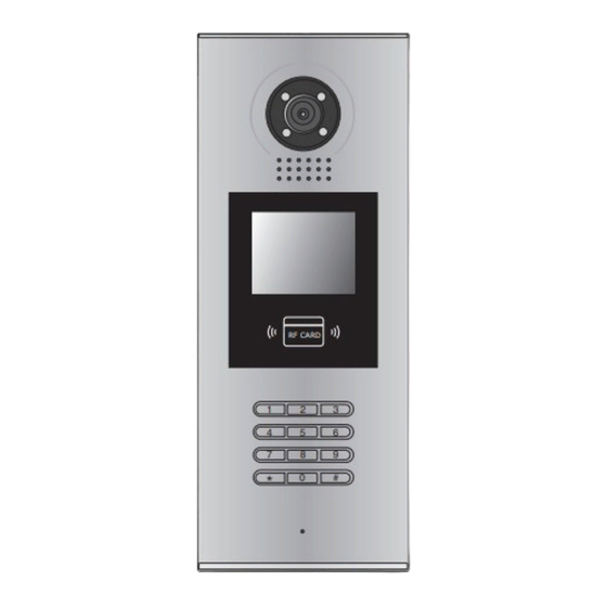
1.Parts and Functions Camera Lens Night View LED Adjustable Camera Speaker LCD Screen Connectiong Port ID Card Window RF CARD Digital Keypad Microphone 128 mm With rainy cover 2. Terminal Descriptions SD Card Slot CN-LK T/R - T/R+ J/KMB JP-LK •... -
Page 4: Door Station Mounting
3.Door Station Mounting Camera angle Drill a hole and attach the The view for rainy Adjust the camera angle and attach the rainy cover to it cover after mounted metal to the panel and wire correctly. Attach screws to fix the Attach the unit to the rainy Attach the baffle to protect metal box... -
Page 5: System Connection
4. System Connection Basic IN-OUT Wiring: CALL UNLOCK TALK/MON 3 4 5 6 IN-USE Code=32, DIP-6=on CALL UNLOCK TALK/MON IN-USE 3 4 5 6 Code=31, DIP-6=off CALL UNLOCK TALK/MON 3 4 5 6 IN-USE Code=1, DIP-6=off 85~260AC ID Code=0(Please refer to section 6->part 3(About Debug Tools)->Basic Tools RF CARD Detail(table 2->ID Code) in details) - Page 6 Basic Star Wiring: CALL CALL UNLOCK UNLOCK TALK/MON TALK/MON 3 4 5 6 IN-USE 3 4 5 IN-USE Impedance Code=32, DIP-6=on Code=31, DIP-6=on OFF ON switch DIP=on,off,off CALL CALL UNLOCK UNLOCK TALK/MON TALK/MON IN-USE IN-USE 3 4 5 6 3 4 5 6 Code=30, DIP-6=on Code=29, DIP-6=on CALL...
- Page 7 Multi Door Stations Wiring: CALL CALL UNLOCK UNLOCK TALK/MON TALK/MON IN-USE IN-USE 3 4 5 6 3 4 5 6 Impedance OFF ON Code=4, DIP-6=on Code=3, DIP-6=on switch DIP=on,off,off CALL CALL UNLOCK UNLOCK TALK/MON TALK/MON IN-USE IN-USE 3 4 5 6 3 4 5 6 Code=2, DIP-6=on Code=1, DIP-6=on...
-
Page 8: Door Lock Connections
5. Door Lock Connections 1. Internal Power Supply Mode Use the power of the system to supply for the electronic lock, so that the lock can be connected to the door station directly, without an additional power supply for the electronic lock. Note that the door station can only output 12Vdc power, therefore the kind of lock is limited. • The rated power of the lock must be less than 12Vdc 300mA when using internal power supply mode • The GND must connect to the negative of the lock, and the COM connect to the positive . • Jumper set to 1-2 position for Power-off-to-Unlock safety type(Normally closed mode); set to 2-3 position for Power-on-to -Unlock type(Normally open mode ). • If different unlocking time is needed to be configured, change the Unlock Timing on door station.(In debug state,press [1 #] --> [1] Installer Setup--> [2]Unlock Timing) A. Connection for Power-on-to-Unlock type: +12V LK - (GND) LK+(COM) set to Normally open on the N.O. - Page 9 2. External Power Supply Mode When the electronic lock is over 12 Vdc, additional power supply for the lock is needed. • The power supply for the lock must be less than 48Vdc 1.5A. • The Jumper must be removed when using external power supply. The default setting is Power-on-to-Unlock type(Normally open mode), if use Power-off-to-Unlock type, change the Unlock Relay mode to Normally closed mode . • If different unlocking time is needed to be configured, change the Unlock Timing on door station.(In debug state,press [1 #] --> [1] Installer Setup--> [2]Unlock Timing) C. Connection for Power-to-Unlock type: set to Normally Open on the +12V LK - (GND) Unlock Relay mode (default) LK+(COM) N.O.
-
Page 10: Door Station Configurations
1. About room code(address): Room Code(also called room address) is a code assigned to each monitor, to identify different monitors; each monitor have a unique room code in one building room Code is stored in each Monitor’s inner EEPROM memory, and does not lose even the monitor is power off. 2. About Debug State: The Debug State is your starting point for using all the applications on CDV-DDP. > > D e b u g S t a t e < < 0 - # R e d i a l RF CARD 1 - #... - Page 11 Table 1: Item Submenu 1. ID Code [0] 2. Unlock Timing [05] 3. Unlock Output [0] 4. Card Memory [0] 5. Doorplate Mode 1. Installer Setup 6. Audio Options ... 7. Parameters ... 8. Installer Code ... 9. Default ... 1. Language [1] 2. Tone Select [03] 3. Tone Volume [08] 4. Unlock Code [1111] 5. Display Mode 2. Setup 6. Clock ... 7. Setup Code ... 8. About ... 9. Default ... 1. Add Card ... 2. Delete By Card 3. Delete By M.code 3. Card Manage 4. Cards Information 5. Format To search the online monitors,input the monitor code 4. Online Monitors number to search To search the online door stations.Max.4 door station 5.
- Page 12 Basic Tools Detail: Table 2(Installer Setup): Factory Item Description If only one door station is installed in this building, set to 0; If multi door stations are installed, primary door station ID Code Single must be set to 0, and other slave door stations must be set from 1 to 3. Note that max. 4 door stations are available in one building To set the time that how long the door keeps open [05] Unlock Timing when door is released. Range from 01 to 99 seconds. 5 seconds To set the unlock mode to match the corresponding lock.Range from 0 to 1. Unlock Output 0:Power-on-to-Unlock Mode(Normally Open Mode) 1:Power-off-to-Unlock Mode(Normally Closed Mode) To set the card location.If set to 0,the card is saved in Card Manage door station.If set to 1, the card is saved in DT-IPC To set the calling mode.If set to 0,it's the auto mode,that means the calling will be activated directly Doorplate Mode after inputting 2 digits code.If set to 1,it's the manual Auto mode mode,that means you should press "#" button to acti- vate the calling after inputting the code. To set talking mode,when cutting voice or mixed voice appears,set to 1. DS-IM talking:set the voice matching between Door Audio Options ... Station and Indoor Monitor DS-NT talking:set the voice matching between Door Station and Guard Unit Parameters ...
- Page 13 Table 2.1(Parameters): Factory Item Description Monitor Timing To show the monitor time,Range from 6s to 600s To show the surveillance time for each Door Station or Switch Timing CCTV camera.Range from 6s to 600s Wait Timing To show the calling wait time,Range from 10s to 600s 30s To show the limitation time of talking,Range from 10s Talk Timing to 600s To enable Indoor Monitor under monitoring state can Monitor & Speak speak to Door Station at same time. If set to 1, talk enabled; set to 0, disabled. To enable Monitors under monitoring state can open the door at the same time.If set to 0, unlock function Monitor & Unlock is disabled; Set to 1, unlock is enable;Set to 2,unlock is enable and close at once;Set to 3,unlock is enable and close in 5s. To show ring times when door station calls monitor.4 Ring Numbers options for choice. If set to 0, ring once. If set to 1,ring twice. If set to 2, ring three times.If set to 3,cycle ring To show the namelist display mode.If set to 0,it's the NameList Display DT-Config display mode.If set to 1,it's the Simulate Mode display mode To show the working mode.If set to 0,it's the apartment Working Mode system mode.If set to 1,it's the villa mode. this section is set on DT-Config software,for more detail informations,please refer to the Note: DT-Config software user instructions.
- Page 14 Table 3(Setup): Factory Item Description To change language.the code format is 4 digits.Please refer Language to part 5,section 10(change door station language) for more detail informations. Select the chime of Door Station in calling wait state, 12 Tone Select chord tunes are available, key in 01 to 12 to select. Adjust the tone volume for door station in calling.Range from Tone Volume 01~15 To change unlock code in Common Code Unlock mode, in Unlock Code [1111] 4-digits format. 1111 is the default unlock code. To select the Door Station screen menu .If set to 0,the Display Mode screen displays the visitor's image when talking.If set to 1,the screen displays icons when talking. To set date and time. Date format:if set to 0,date format is DD/MM/YY,if set to Clock ... 1,date format is MM/DD/YY. Time format: if set to 0,time format is 24 hour standard.If set to 1,time format is 12 hour standard. Setup Code To change the Program Code. [88888888] 1. Hardware version---To show the Door Station(including ACS) hardware information 2. Software version ---To show the Door Station(including ACS) software information 3. Manufacture Date---To show the manufacturing date 4. Dialing Counts---To show the call operation counts 5. Calls Counts---To show the established calling counts 6. Unlock Counts---To show the unlock operation counts About ... 7. Standby Voltage---To show the voltage that the door sta- tion in standby.
- Page 15 Table 4(Card Manage): Factory Item Description Add Card ... To add the user card Delete By Card To delete card by user card Delete By M.code To delete card by room code Cards Information To show the informations about cards Format To format informations about cards 4. Calling and Unlock Operation: The door station is a digital station with 320*240 pixels LCD screen, color CCD camera, night view LED, and digital keypad. Visitors can call the apartment by dialing the Flat Code (apartment number) on the keypad. If they don’t know the Flat Code (apartment number), they can search the name list on the screen. If the door station is in standby, visitors need to press '9#' to display the user name list. Press"#" key to scroll next/last page. and use key 1 to 8 key on each page to call the desired flat. Residents can open the door by using their unique Unlock Code (four-digit PIN code). If the door station is in standby mode, press '#' key, then input the four-digit unlock to open the door. Please refer to part 5,section 7(How to use code unlock function) for more detail information. If the door station works as apartment system mode,input 01~32 to call the relevant mon- Note: itor.If the door station works as villa mode,input 01 to call the monitors which its code is from 00~15. Input 02 to call the monitors which its code is from 16~31.please refer to table 2.1(work- ing mode) 5. About Default Set: The Default Set is very important. When the door station miss up the settings in anyway, the most quickly and easy way to solve the problem is to activate the default setting on door sta- tion. The default settings already have all the right settings for one-building system, that means the system will work normally without any additional settings. .
- Page 16 1 . I D C o d e . [ 1 ] > > D e b u g S t a t e < < 2 . U n l o c k T i m i n g [ 0 5 ] 3 .
- Page 17 7. Change Installer Code(administrator password): The Installer Code is the password to access the door station debug State. The default Installer Code is '66666666'. Note that if the Default Set have been activated, the Installer Code will be set to default value. 1 . I D C o d e [ 1 ] > > D e b u g S t a t e < < 2 . U n l o c k T i m i n g [ 0 5 ] 3 .
- Page 18 9. Change Unlock Code: If door station runs as Debug State, you can press “1#” to activate Tools Menu, then select “2” to enter setup page,then select 4 item.If it runs as Normal State, follow these steps: 1 . L a n g u a g e [ 1 ] 4 . U n l o c k C o d e [ 1 1 1 1 ] 2 . To n e S e l e c t [ 0 3 ] 3 .
- Page 19 1 . A d d C a r d . . . 1 . A d d C a r d . . . 1 . A d d C a r d . . . [ - - ] [ 0 1 ] [ 0 1 ] C a r d numbs : 1 5 9 7 7 1 3 1...
- Page 20 [ - - - - - - - - ] will be asked,input 8 digits installer Please Input Password password (66666666 by default),then press" #" key to save,format operation * Back # Save is activated.all card information will be cleared. 11. Change Door Station Language: It's convenient to change the user interface for CDV-DDP.Just put the config files to the SD card and by means of the digital keypad of door station,only 30 seconds is needed to update. Insert SD card SD Card Slot Step 1: Insert the SD card which is con- CN-LK tained config files into the SD card slot T/R - T/R+ where is at the back of the door station.
- Page 21 1 . L a n g u a g e [ 1 ] 1 . L a n g u a g e 2 . To n e S e l e c t [ 0 3 ] 3 . To n e V o l u m e [ 0 3 ] Setup [ - - - - ] [ 8002 ]...
- Page 22 Check online monitors: > > D e b u g S t a t e < < 4 . O n l i n e M o n i t o r s 1 . I n s t a l l e r S e t u p Tools 0 - # R e d i a l...
-
Page 23: Specification
7. Specification ● Power supply: DC24V(Powered by DPS) ● Camera Lens : 1/4 ACS 4T image sensor with DSP processor ● Power consumption: Standby 3W;Working status 9W ● Screen: 3.5 inch TFT ● Resolution: 320(R, G, B)X240 pixels ● Video signal: CCIR/EIA Optional ●... - Page 24 The design and specifications can be changed without notice to the user. Right to interpret and copyright of this manual are preserved. Model: CDV-DDP...
Need help?
Do you have a question about the CDV-DDP and is the answer not in the manual?
Questions and answers