Table of Contents
Advertisement
Quick Links
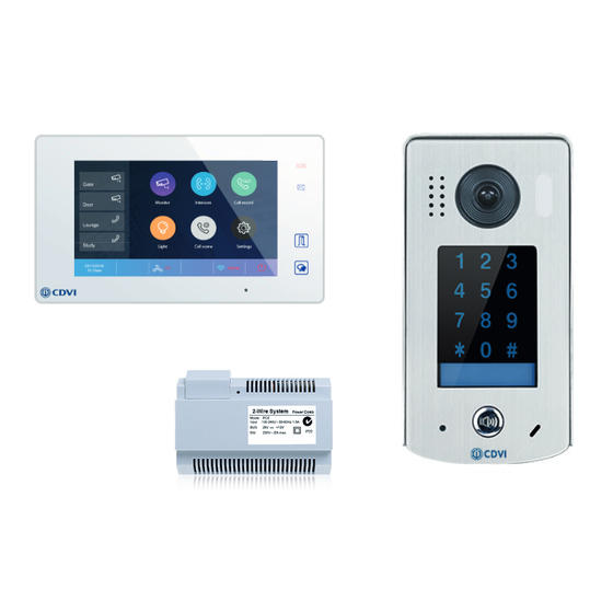
CDV4796KP-DX Kit
The 2EASY kits from CDVI off er convenient and high quality audio entry.
Connection throughout is 2-wire, non polarised, so installation and maintenance is
simple and straightforward.
The CDV47DX now includes Wi-Fi connection and a new mobile app allowing users to
control access from their phone by receiving calls or remotely releasing multiple locks.
Robust door stations with stylish handsets - it all adds up to a sophisticated and fl exible
Robust door stations with stylish handsets - it all adds up to a sophisticated and fl exible
audio entry system.
audio entry system.
Overview
• Black or white monitor
• Door station with integral keypad
• 2-wire connection
• Expandable
• Compatible with 2Easy video system
• Mobile app available on Android and IOS
• Free operation with no monthly fees
01628 531300
The 2EASY system from CDVI off er convenient and high
quality video entry. Connection throughout is 2-wire, non
polarised providing simple and effi cient installation and
maintenance.
Datasheet
www.cdvi.co.uk
Advertisement
Table of Contents

Related Manuals for CDVI CDV4796KP-DX


Summary of Contents for CDVI CDV4796KP-DX
- Page 1 Datasheet CDV4796KP-DX Kit The 2EASY kits from CDVI off er convenient and high quality audio entry. Connection throughout is 2-wire, non polarised, so installation and maintenance is simple and straightforward. The CDV47DX now includes Wi-Fi connection and a new mobile app allowing users to control access from their phone by receiving calls or remotely releasing multiple locks.
-
Page 2: Data Sheet
Display resolutions: 800*3 (R, G, B) x 480 pixels Electrical Specifi cations Power input: 12/24 Vdc Power supply: 20 to 28 Vdc for indoor monitor Power consumption: 7W (working), 0.3W (standby) Dimensions Dimensions: 132 x 226 x 18mm App download Android 01628 531300 www.cdvi.co.uk... - Page 3 Power Supply: 24Vdc Power Consumption: 105mA (working), 15mA (standby) Lock Power Supply: 12Vdc, 280mA (Internal power - Fail secure only) Wiring 2-wire No polarity Dimensions - CDV96KP Dimensions: 182 x 93 x 44mm Environment: -15°C to 55°C 01628 531300 www.cdvi.co.uk...
-
Page 4: Input Specifications
Input voltage: 100-240Vac Input frequency: 50-60Hz SW port input voltage: max 230Vac, 2A Output Specifi cations Rated output voltage: 28Vdc + 2Vdc Rated output current: 1.5A Dimensions Dimensions: 140 x 90 x 60mm Environment: -10°C to 50°C 01628 531300 www.cdvi.co.uk... -
Page 5: Cable Type
2 Easy 1 & 2 User (Kit) Cable & Distance Specifications CDV47DX CDV43 CDV43 CDV43 240AC Daisy Chain Shown – Use CDV-DBC4A for Star Configuration CDV-PC6 CDV-PC6 NOTE: Max distance from DBC4A to Device is 40m B Max B Max B Max B Max Cable Type... - Page 6 The installer’s choice CDV4796KP-DX KIT MANUAL 01628 531300 www.cdvi.co.uk...
- Page 7 7: Cable Requirements 1. CDV4796KP-DX KIT CONTENTS 1 x CDV96KP 1 Button Video Entry Panel c/w Keypad 1 x CDV-PC6 Power/Bus Combiner 1 x CDV47DX TFT Touch screen Internal Monitor 1 x 145mm Din Rail 1 x CDV4796KP-DX Kit Manual...
- Page 8 The installer’s choice 2 : CDV96KP Parts and Functions 30 mm Rain Cover CDV96 KP [7] Microphone [1] Camera lens [4] Touch keypad [8] Power LED [2] Camera LED [5] Keypad LED [3] Speaker [6] Call button 2. 1: Terminal Descriptions •...
- Page 9 The installer’s choice 3: Mounting Drill holes in the wall to match the size of Connect the wiring (see pg 4) screws and attach the rain cover to the wall. Us ing a screwdriver secure the panel Attach the panel to the rain cover 3 : CDV -PC6A Parts and Functions 3.1: Description The PC6A is a power/bus combiner unit, which is designed for the CDV 2Easy 2 wire...
- Page 10 The installer’s choice 3. 2: Terminal Descriptions 1 2 3 100~240 Vac BUS(IM) BUS(DS) PG : Earth ground terminal . AC input terminal . AC input terminal . LED: P ower indicator, on when power connected . B us control terminal. BUS(IM): I ndoor monitor connection terminal.
-
Page 11: Terminal Description
The installer’s choice 4: CDV47 Parts and Functions 4.1: Terminal description L1,L2: Bus line terminal. SW+,SW-: Doorbell input conne ction port. Ring,GND: Extension buzzer input connection port. 1 2 3 4 5 6 USB-Wi-Fi adaptor NC: Reserved. DIP switchesBit1~Bit5: Reserved. Bit6: Video impedance matching switch. -
Page 12: Function Status
The installer’s choice 4.3: Main Menu The Main menu is your starting point for using all the applications on your monitor. Touch Unlock button, or touch anywhere of the screen on monitor in standby mode, the Main menu will appear as follow: Monitor Intercom Touch to view outdoor scene. -
Page 13: Installer Settings
The installer’s choice Icon Meaning Description Wi-Fi connection active and not connected Wi-Fi connection disabled Touch to enter Wi-Fi setting interface in shortcut. Wi-Fi connection active and configured 4.4: Installer Settings This section contains the device address setting and system settings. 1. -
Page 14: Unlock Time Setting
The installer’s choice 4.6: Unlock Time Setting Setting the unlock time. Installer Installer Call Tune Current addtess [01] Call Tune Unlock time [03] General IPC Setting General Unlock mode [Open] Installer Monitor list manage Installer Auto reboot [Enable] Wireless System settings Wireless Reboot About... -
Page 15: System Wiring And Connections
The installer’s choice 5: System Wiring and Connections 5.1: Basic Connection Code=00, DIP6=on PC6A BUS(IM) BUS(DS) L1 L2 PL S1+ GND DIP Switches 1 2 3 4 5 6 Doorbell Button Switch 5.2: Multi Door Stations Connection 4# Camera 3# Camera 2# Camera 1# Camera (Device Address:3) - Page 16 The installer’s choice 5.3: Basic IN-OUT Wiring in Standard Mode • The door station is compatible with other Code=1, DIP6=on monitors within the 2Easy range. (Slave 3) • For the last monitor connected to the system, DIP6 should be set to ON. Code=1, DIP6=off (Slave 2) Code=1, DIP6=off...
- Page 17 The installer’s choice 5.4: Star Topology Wiring With CDV-DBC4A1 in Standard Mode Code=0 Master,DIP6=on Code=0 Slave 1,DIP6=on Impedance OFF ON switch Code=0 Slave 2 DIP6=on Code=0 Slave 3,DIP6=on 100~240VAC CDV-BDU CDV-PC6 CDV-RLC CDV-DBC4A1 BUS(IM) BUS(DS) Optional functional modules: CDV-BDU bus amplifier module CDV-RLC staircase light controller module CDV-DBC4 2/4 inputs branch distributor ID=0...
-
Page 18: Door Lock Controlled With Internal Power
The installer’s choice 5.5: Electric Lock Connection Door Lock Controlled with Internal Power Note: 1. This mode only supports strike type locks. Jumper position 2. Strike type lock s of Power- on -to-unlock (fail secure) type should be used. L2 LK+ LK- 3. - Page 19 The installer’s choice 5.6: Setting User Codes (PIN) Setting a User Code for Lock 1(User Group1) and Lock 2(User Group 2) on the CDV Enter programming mode by entering 1234#, 2 beeps will be heard. (Master code 1234 can be changed if required - for more setting please refer to the CDV96KP manual) Setting the code Setting the code for user group1...
-
Page 20: Specifications
The installer’s choice 6: Specifications: 6.1: CDV91S Specifications LOCK ● Power Supply : DC 24V ● Power Consumption: Standby 14mA; Working status 122mA ● Camera: Color CMOS, 2.0 Mega pixel 1/2.7’’ fisheye camera,170 wide angle ● Lock Power supply: 12Vdc, 250mA(Internal power) ●... -
Page 21: Basic In-Out Wiring Mode
The installer’s choice 7: System Wiring and Connections The maximum distance of the wiring is limited in the 2Easy system. Using different cables may also affect the maximum distance which the system can reach. Basic IN-OUT Wiring Mode Cable and distance (unit:m) Cable Usage ≤2 IM ≤16 IM... - Page 22 The installer’s choice Star Topology Wiring Mode With CDV-DBC4 CDV-DBC4A1 CDV-PC6 Cable and distance (unit:m) Cable Usage Belden 9740 UTP 2x0.75mm Belden 8471 UTP 2x1mm...
Need help?
Do you have a question about the CDV4796KP-DX and is the answer not in the manual?
Questions and answers