Table of Contents
Advertisement
Quick Links
Advertisement
Table of Contents

Related Manuals for CDVI CDV-91


Summary of Contents for CDVI CDV-91
- Page 1 2 -Wire Intercom System USER MANUAL Model: CDV-91...
-
Page 3: Parts And Functions
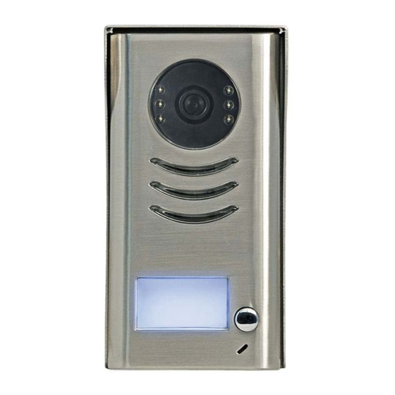
1.Parts and Functions Camera Lens Night View LED Speaker Nameplate Call Button Microphone Rainy Cover 90 mm 23 mm 2.Terminal Descriptions 1 2 3 Lock Control Jumper Doorstation Code DIP MIC adjustment SPK adjustment Main Connect Port S 2 + S - P L S 1 + B U S... -
Page 4: Specifications
• To select the lock type: see 5.2.1 , 5.2.2 Lock Control Jumper: • Total 4 door stations can be supported,see 6.1 Door Station Code DIP: • To connect the bus line and the electronic locks. Main Connect Port: • BUS: Connect to the bus line, no polarity. •... -
Page 5: Mounting With Rainy Cover
4.2 Mounting With Rainy Cover 160-165cm 4.3 Placing Name Label Move the plastic cover away to open the transparent name label cover, insert a name paper, then put the plastic cover back to the panel. name label... -
Page 6: Adjusting Camera Angle
4.4 Adjusting Camera Angle Use a screwdriver to loosen the screw and then adjust the angle of the camera ,then fix the screw. 5.System Wiring and Connections 5.1 Basic Connection monitor L1 L2 PL S1+ S2+ S-... -
Page 7: Electric Lock Connection
5.2 Electric Lock Connection 5.2.1 Door Lock Controlled with Internal Power Note: Electronic lock of Power-on-to-unlock type should be used. The door lock is limited to 12V, and holding current must be less than 250mA. The door lock control is not timed from Exit Button(EB). Parameter of Monitor must be set to 0 (by default). - Page 8 connect one lock connect two locks Take off the Jumper Take off the Jumper POWER POWER SUPPLY SUPPLY LOCK LOCK LOCK 5.2.3 Unlock parameter setting(set on monitor) H/W : a1.3 S/W: V17.11.418.00 Manual Monitor Intercom Multimedia Local addr: Monitor Unlock timing: Video standard: UI-CODE: Close...
-
Page 9: Multi Door Stations Connection
5.3 Multi Door Stations Connection 4# Camera 3# Camera 2# Camera 1# Camera ID=10 ID=11 ID=01 ID=00 monitors L1 L2 PL S1+ S2+ S- L1 L2 PL S1+ S2+ S- L1 L2 PL S1+ S2+ S- L1 L2 PL S1+ S2+ S- DIP=on,off,off A B C D DBC4... -
Page 10: With Dbc4 Wiring Mode
5.4.2 With DBC4 Wiring Mode monitor monitor 3 4 5 6 3 4 5 6 Impedance Code=15, DIP-6=on Code=14, DIP-6=on OFF ON switch DIP=on,off,off monitor monitor 3 4 5 6 3 4 5 6 Code=12, DIP-6=on Code=13, DIP-6=on monitor monitor 3 4 5 6 3 4 5 6 Code=3, DIP-6=on... -
Page 11: Dip Switches Settings Of Door Station
6.Setup ON(1) OFF(0) 6.1 DIP Switches Settings of Door Station Total 2 bits on the DIP switches can be configured.The switches can be modified either before or after installation. Bit state Descriptions Default setting, ID = 0(00), set to the first Door Station. ID = 1(10), set to the second Door Station. - Page 12 Bit-1 to Bit-5 are used to User Code setting.The CDV-91 responds to 0~15 . Bit state User Code Bit state User Code Bit state User Code Code=0 Code=6 Code=11 3 4 5 3 4 5 3 4 5 Code=1 Code=7...
-
Page 13: Cables Requirements
7.Cables Requirements The maximum distance of the wiring is limited in the DT system. Using different cables may also affect the maxi- mum distance which the system can reach. The farest monitor monitor with two or four monitors monitor monitor DBC4 When Monitor quantity <... - Page 16 The design and specifications can be changed without notice to the user. Right to interpret and copyright of this manual are preserved. Model: CDV-91...
Need help?
Do you have a question about the CDV-91 and is the answer not in the manual?
Questions and answers