
Related Manuals for CDVI CDV96KP


Summary of Contents for CDVI CDV96KP
-
Page 1: User Manual
English 2-Wire Video Outdoor Station User Manual CDV96/KP CDV96KP-SF CDV-ENG-611(F)KP-V1 190307... -
Page 2: Table Of Contents
Contents 1.Parts and Functions..................... 1 2.Terminal Descriptions ..................2 3.Mounting ......................2 4.System Wiring and Connections ................. 4 5. Pan-tilt & Zoom ....................8 6. Functions Setting Up ..................9 7.Unlock Operations ....................17 8.Specifications ...................... 17 9.Cables Requirements ..................18 10.Precautions...................... -
Page 3: Parts And Functions
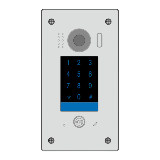
1.Parts and Functions 30 mm Rain Cover CDV96KP CDV96KP Mounting box [7] Microphone [1] Camera lens [4] Touch keypad [8] Power LED [2] Camera LED [5] Keypad LED [3] Speaker [6] Call button... -
Page 4: Terminal Descriptions
P L S 1 + Main Connect Port port. 3. Mounting CDV96KP Mounting Drill holes in the wall to match the size of Connect the wiring (see pg 4) screws and attach the rain cover to the wall. Using a screwdriver secure the panel... -
Page 5: Placing Name Label
CDV96KP-SF Mounting Make a hole in the wall to match the size of Connect the wiring (see pg 4.) the mounting box and fix to the wall. Attach the panel to the mounting box and use screws supplied to fix the panel Placing Name Label Use a screwdriver to remove the screw holding the panel in place. -
Page 6: System Wiring And Connections
4.System Wiring and Connections Basic Connection Code=00, DIP6=on PC6A BUS(IM) BUS(DS) L1 L2 PL S1+ GND DIP Switches 1 2 3 4 5 6 Doorbell Button Switch Electric Lock Connection Door Lock Controlled with Internal Power Note: 1 2 3 This mode only supports Fail Secure (power on to unlock) Strikes Jumper position in 2-3... -
Page 7: Door Lock Controlled With Dry Contact
@ + OK: Address Setting Menu System Verson 00.01.00 Display Driver Font Note: 1. The CDV96KP must be connected before setting. 2. A set parameter will be saved in CDV96KP automatically, it only needs to be set on one monitor. - Page 8 Basic IN-OUT Wiring Mode Code=00 Slave 2 Code= 00 Slave 1 Code=0 Master 100~240VAC PC6A BUS(IM) BUS(DS) * IMPORTANT: Subject to cable type. Please see cable distance chart on pg 18 or call CDVI Technical Support for more information. (Device Address:0)
- Page 9 Slave 1 Impedance OFF ON switch Code=00 Code=00 Slave 3 Slave 2 100~240VAC PC6A BUS(IM) BUS(DS) * IMPORTANT: Subject to cable type. Please see cable distance chart on pg 18 or call CDVI Technical Support for more information. (Device Address:0)
-
Page 10: Pan-Tilt & Zoom
5. Pan-tilt & Zoom Note: this function requires a monitor with fish-eye function to support i.e. CDV47DX or CDV47MG If greater detail about visitors is required,move to the desired position by touching on the screen to view the image in pantilt & zoom mode. When an image at a door station is displayed,move to the desired position by touching on the screen to view the image in zoom mode. -
Page 11: Functions Setting Up
6. Functions Setting Up This section explains the settings of each function, please refer to the following table: About the programming mode: Enter the master code to open the programming mode, enter the corresponding setting code to perform the required function. Enter the value required using the setting codes below. Press " " to exit the setting mode. •... - Page 12 MIC Volume Adjust Valid keys: 0~9 (Microphone) SPK Volume Adjust Valid keys: 0~9 Device Address Valid keys: 0~3 Night Light Level Valid keys: 0~5 Reserved Reserved Reserved 14~17 (not used) Temporary Code 1 ~ 12 digits (Single Use only) Valid keys:0~9 Password for relay1 Temporary Code 1 ~ 12 digits...
- Page 13 Each operation is indicated by the lighting up of the different color of digital key and nameplate , and by the sounding of the buzzer. The color of key indicator Input the master code. (Default: [ ] +[#] ) (blue-white) Beep+, Beep 1.Reset all settings 2.Setting the master code...
- Page 14 The color of key indicator Input the master code. (Default: [ ] +[#]) Beep+, Beep (blue-white) 5.Setting the unlock mode 6.Setting operation tone 7.Reset code setting 8. &# function setting (Default 0(opened)) (Default ON) (Default Normal) Enter the setting code. Enter the setting code.
- Page 15 The color of key indicator Input the master code. (Default: [ ] +[#]) Beep+, Beep (blue-white) 11.MIC volume adjust 9. Language 10.Voice Volume 12.SPK volume adjust setting setting (Default 2) (Default 5) (Default:7) (Default:4) IEnter the setting code. Enter the setting code. Enter the setting code.
- Page 16 The color of key indicator Input the master code. (Default: [ ] +[#]) Beep+, Beep (blue-white) 13. Device address setting 14.Night light level setting (Default 0) (Default 4) Enter the setting code. Enter the setting code. 12+# 13+# The colour of key indicator The colour of key indicator Beep+, Beep Beep+, Beep...
- Page 17 Input the master code. The color of key indicator (Default: [ ]+[#] ) Beep+, Beep (blue-white) 17.Setting the code 18.Setting the code 15.Temporary Code 16.Temporary Code for user group1 for user group2 (Single Use only) (Single Use only) Password for relay1 Password for relay2 Locations 20 to 59...
- Page 18 The color of key indicator Input the master code. (Default: [ ]+[#] ) Beep+, Beep (blue-white) 19.Work mode setting 20.Call address setting 21.Display scene setting 22.TS_Sensitivity (Default:villa:00,16; (Default:1/villa) (Default:0) (Default:3) apartment:00~31) Enter the setting code. Enter the setting code. Enter the setting code. Enter the setting code.
-
Page 19: Unlock Operations
• Lock Power supply: 12Vdc, 280mA(Internal Power); • Number of relay circuits: 2(the second lock requires external device to support) • Mounting: Surface mounting(CDV96KP) • Flush mounting (CDV96KP-SF) • Working temperature: -15ºC ~ +55ºC • Dimension: 182(H)×93(W)×44(D)mm(CDV96KP) • 220(H)×120(W)×50(D)mm(CDV96KP-SF) -17-... -
Page 20: Cables Requirements
9. Cable Requirements The maximum distance of the wiring is limited within the 2Easy system. Using different cables may also affect the maximum distance which the system can reach. Two to four monitors from outputs A, B, C & D of DBC4A monitor monitor DBC4A1... -
Page 21: Precautions
10. Precautions • Please clean the unit with soft cotton cloth, don't use any impregnated cloth or chemical clean agent. If necessary, please use a little pure water or dilute soap water to clean the dust. • The unit is weather resistant. However do not spray high pressure water on access control keypad directly. Excessive moisture may cause problems with the unit. - Page 22 Note...
- Page 23 Note...
- Page 24 The design and specifications can be modified without notice to the user. Right to interpret and copyright of this manual are reserved. CDV-ENG-611(F)KP-V1 190307...
Need help?
Do you have a question about the CDV96KP and is the answer not in the manual?
Questions and answers