Table of Contents
Advertisement
Quick Links
Advertisement
Table of Contents

Related Manuals for CDVI CDV91S


Summary of Contents for CDVI CDV91S
- Page 1 English CDVI 2-Wire Video Outdoor Station User Manual ENG-CDV91S-V1 1903...
-
Page 2: Parts And Functions
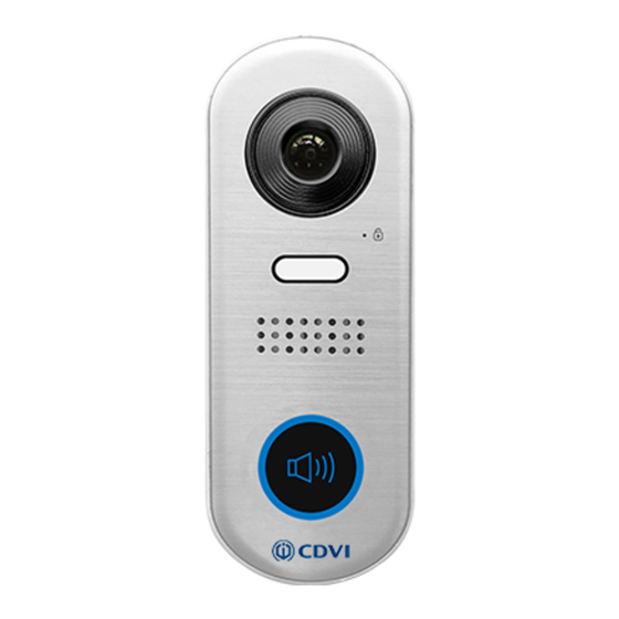
1.Parts and Functions Camera Lens LED_UNLOCK LED_CAM Speaker LED_KEY KEY_CALL Microphone 2.Terminal Descriptions DIP: Bit 1&2: sets the door station address, a total of 4 door ON(1) OFF(0) stations can be supported. Please refer to door station address setting. Bit 3&4: sets the unlock time for door station. Please refer to unlock time setting. - Page 3 3.Mounting 1. Installation height for door station usually is 145~160cm. 2. Use screws to fix the back panel to the wall and connect the cables correctly. 3. Attach the front panel to the back panel, then use the screw to secure the panel.
-
Page 4: System Wiring And Connections
4.System Wiring and Connections Basic Connection Code=00, DIP6=on CDV-PC6 BUS(IM) BUS(DS) L2 LK+ LK- DIP Switches 1 2 3 4 5 6 Doorbell Button Switch Electric Lock Connection Door Lock Controlled with Internal Power Note: This mode only supports strike type locks. Jumper position Strike type locks of Power-on-to-unlock (fail secure) type should be used. -
Page 5: Multi Door Stations Connection
Door Lock Controlled with Dry Contact Note: An external power supply must be used according Jumper position to the lock power requirements. The internal relay contact is restricted to AC or DC Max 24V/1A. L2 LK+ LK- Setup the Unlock Mode of Monitor for different lock types. -
Page 6: Multi Monitors Connection
Multi Monitors Connection Basic IN-OUT Wiring in Standard Mode • The door station is compatible with other Code=1, DIP6=on monitors within the 2Easy range . (Slave 3) • Please set the door station into group calling mode if there are more than 4 monitors in villa(Refer to Page 8) •... - Page 7 Star Topology Wiring With CDV-DBC4A1 in Standard Mode Code=0 Master, 0 Slave 1,DIP6=on Impedance OFF ON switch Code=0 Slave 2 0 Slave 3,DIP6=on 100~240VAC CDV-BDU CDV-PC6 CDV-RLC CDV-DBC4A1 BUS(IM) BUS(DS) Optional functional modules: CDV-BDU bus amplifier module CDV-RLC staircase light controller module CDV-DBC4A1 2/4 inputs branch distributor ID=0 •...
-
Page 8: Pan-Tilt & Zoom
5. Pan-tilt & Zoom Note: this function requires a monitor with fish-eye function to operate. It is possible to adjust the display mode for viewing images of a fish-eye door station by using the 5 direction pad button. When an image at a door station is displayed, move to the desired position by touching on the screen to view the image in zoom mode. -
Page 9: Led Status
6. LED status Different LEDs ON to represent different states. Please refer to the figure below. LEDs LED_UNLOCK LED_CAM LED_KEY Status (by default) (by default) Monitoring Auto (by default) Calling Auto Flash quickly (by default) Talking Auto Flash slowly Unlock Upgrade Setup/ Initilization... -
Page 10: Unlock Time Setting
7. Door station address setting ON(1) OFF(0) 2 bits on the DIP switches can be configured. The switches can be modified either before or after installation. Bit state Descriptions Default setting, ID = 0(00), set to the first Door Station. ID = 1(10), set to the second Door Station. - Page 11 9. Setup Set bit 6 to ON or connect power and within 10 secs, press and hold KEY_CALL to enter the setting mode. Switch Language Voice Press KEY_CALL to switch Press KEY_CALL to switch Press KEY_CALL to switch language voice prompt mode. language voice prompt mode.
-
Page 12: Specifications
10. Specifications • Power Supply : DC 24V ; • Power Consumption: Standby 14mA; Working status 122mA; • Camera: Color CMOS, 2.0 Mega pixel • 1/2.7’’ fisheye camera,170 wide angle; • Lock Power supply: 12Vdc, 250mA(Internal Power); • Mounting: Surface mounting •... -
Page 13: Cables Requirements
12. Cables Requirements The maximum distance of the wiring is limited in the 2Easy system. Using different cables may also affect the maximum distance which the system can reach. Basic IN-OUT Wiring Mode Cable and distance(unit:m) Cable Usage ≤2 IM ≤16 IM Belden 9470 UTP 2x0.75mm Belden 8471 UTP 2x1mm... - Page 14 Star Topology Wiring Mode With CDV-DBC4A1 CDV-DBC4A1 CDV-PC6 Cable and distance(unit:m) Cable Usage Belden 9740 UTP 2x0.75mm Belden 8471 UTP 2x1mm...
- Page 15 Note...
- Page 16 The design and specifications can be modified without notice to the user. Right to interpret and copyright of this manual are reserved. ENG-CDV91S-V1 1903...
Need help?
Do you have a question about the CDV91S and is the answer not in the manual?
Questions and answers