Table of Contents
Advertisement
Quick Links
Advertisement
Table of Contents

Related Manuals for CDVI CDV4791S-DX


Summary of Contents for CDVI CDV4791S-DX
- Page 1 The installer’s choice CDV4791S-DX KIT MANUAL 01628 531300 www.cdvi.co.uk...
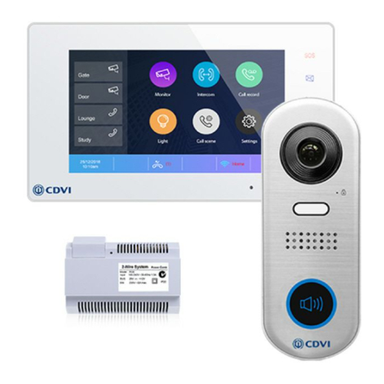
- Page 2 5.6: Cable Requirements 6: Specifications 6.1: CDV91S 6.2: CDV-PC6 6.3: CDV47DX 7: Cable Requirements 1. CDV4791S-DX KIT CONTENTS 1 x CDV91S 1 or 2 Button Video Entry Panel 1 x CDV-PC6 Power/Bus Combiner 1 x CDV47DX TFT Touch screen Internal Monitor...
-
Page 3: Terminal Descriptions
The installer’s choice 2 : CDV91S Parts and Functions Camera Lens LED_UNLOCK LED_CAM Speaker LED_KEY KEY_CALL Microphone 2. 1: Terminal Descriptions DIP: Bit 1&2: set s the door station address, a total of 4 door stations can be supported. Please refer to door station address setting. - Page 4 The installer’s choice 3: Mounting 3 : CDV -PC6A Parts and Functions 3.1: Description The PC6A is a power/bus combiner unit, which is designed for the CDV 2Easy 2 wire system to supply power for the external station, internal monitor and other accessories on the bus.
- Page 5 The installer’s choice 3. 2: Terminal Descriptions 1 2 3 100~240 Vac BUS(IM) BUS(DS) PG : Earth ground terminal . AC input terminal . AC input terminal . LED: P ower indicator, on when power connected . B us control terminal. BUS(IM): I ndoor monitor connection terminal.
-
Page 6: Terminal Description
The installer’s choice 4: CDV47 Parts and Functions 4.1: Terminal description L1,L2: Bus line terminal. SW+,SW-: Doorbell input conne ction port. Ring,GND: Extension buzzer input connection port. 1 2 3 4 5 6 USB-Wi-Fi adaptor NC: Reserved. DIP switchesBit1~Bit5: Reserved. Bit6: Video impedance matching switch. -
Page 7: Function Status
The installer’s choice 4.3: Main Menu The Main menu is your starting point for using all the applications on your monitor. Touch Unlock button, or touch anywhere of the screen on monitor in standby mode, the Main menu will appear as follow: Monitor Intercom Touch to view outdoor scene. -
Page 8: Installer Settings
The installer’s choice Icon Meaning Description Wi-Fi connection active and not connected Wi-Fi connection disabled Touch to enter Wi-Fi setting interface in shortcut. Wi-Fi connection active and configured 4.4: Installer Settings This section contains the device address setting and system settings. 1. -
Page 9: Unlock Time Setting
The installer’s choice 4.6: Unlock Time Setting Setting the unlock time. Installer Installer Call Tune Current addtess [01] Call Tune Unlock time [03] General IPC Setting General Unlock mode [Open] Installer Monitor list manage Installer Auto reboot [Enable] Wireless System settings Wireless Reboot About... -
Page 10: System Wiring And Connections
The installer’s choice 5: System Wiring and Connections 5.1: Basic Connection Code=00, DIP6=on CDV-PC6 BUS(IM) BUS(DS) L2 LK+ LK- DIP Switches 1 2 3 4 5 6 Doorbell Button Switch 5.2: Multi Door Stations Connection 4# Camera 3# Camera 2# Camera 1# Camera (Device Address:3) (Device Address:2) - Page 11 The installer’s choice 5.3: Basic IN-OUT Wiring in Standard Mode • The door station is compatible with other Code=1, DIP6=on monitors within the 2Easy range. (Slave 3) • Please set the door station into grou p calling mode if there are more than 4 monitors in villa (Refer to Page 8) .
- Page 12 The installer’s choice 5.4: Star Topology Wiring With CDV-DBC4A1 in Standard Mode Code=0 Master,DIP6=on Code=0 Slave 1,DIP6=on Impedance OFF ON switch Code=0 Slave 2 DIP6=on Code=0 Slave 3,DIP6=on 100~240VAC CDV-BDU CDV-PC6 CDV-RLC CDV-DBC4A1 BUS(IM) BUS(DS) Optional functional modules: CDV-BDU bus amplifier module CDV-RLC staircase light controller module CDV-DBC4 2/4 inputs branch distributor ID=0...
-
Page 13: Door Lock Controlled With Internal Power
The installer’s choice 5.5: Electric Lock Connection Door Lock Controlled with Internal Power Note: 1. This mode only supports strike type locks. Jumper position 2. Strike type lock s of Power- on -to-unlock (fail secure) type should be used. L2 LK+ LK- 3. -
Page 14: Specifications
The installer’s choice 6: Specifications: 6.1: CDV91S Specifications LOCK ● Power Supply : DC 24V ● Power Consumption: Standby 14mA; Working status 122mA ● Camera: Color CMOS, 2.0 Mega pixel 1/2.7’’ fisheye camera,170 wide angle ● Lock Power supply: 12Vdc, 250mA(Internal power) ●... -
Page 15: Basic In-Out Wiring Mode
The installer’s choice 7: System Wiring and Connections The maximum distance of the wiring is limited in the 2Easy system. Using different cables may also affect the maximum distance which the system can reach. Basic IN-OUT Wiring Mode Cable and distance (unit:m) Cable Usage ≤2 IM ≤16 IM... - Page 16 The installer’s choice Star Topology Wiring Mode With CDV-DBC4 CDV-DBC4A1 CDV-PC6 Cable and distance (unit:m) Cable Usage Belden 9740 UTP 2x0.75mm Belden 8471 UTP 2x1mm...
Need help?
Do you have a question about the CDV4791S-DX and is the answer not in the manual?
Questions and answers