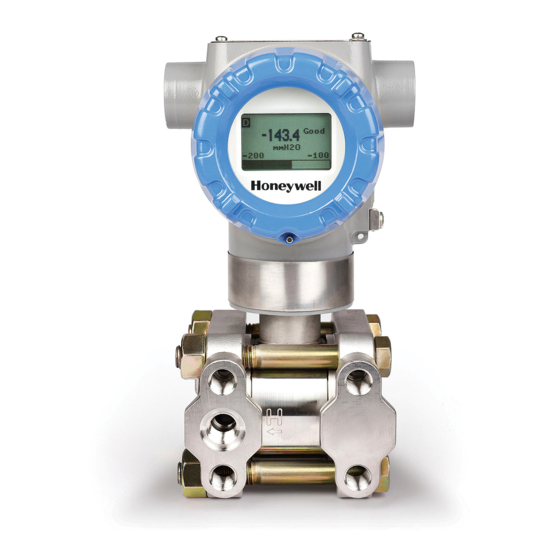
Honeywell ST700 User Manual
Foundation fieldbus pressure transmitter
Hide thumbs
Also See for ST700:
- User manual (274 pages) ,
- Installation manual (9 pages) ,
- Quick start installation manual (24 pages)

Related Manuals for Honeywell ST700


Summary of Contents for Honeywell ST700
- Page 1 FOUNDATION Fieldbus ST 700 Pressure Transmitter User's Guide 34-ST-25-48 Revision 2.0 July 2014 Honeywell Process Solutions...
-
Page 2: Copyrights, Notices And Trademarks
© Copyright 2014 by Honeywell, Inc. Revision 2, July 2014 While this information is presented in good faith and believed to be accurate, Honeywell disclaims the implied warranties of merchantability and fitness for a particular purpose and makes no express warranties except as may be stated in its written agreement with and for its customers. -
Page 3: About This Document
About This Document This guide provides the details of programming Honeywell ST 700 SmartLine Pressure Transmitters for applications involving FOUNDATION Fieldbus protocol. For installation, wiring, and maintenance information, refer to the ST 700 SmartLine Pressure Transmitter User Manual. The configuration of your transmitter depends on the mode of operation and the options selected for it with respect to operating controls, displays and mechanical installation. - Page 4 Patent Notice The Honeywell ST 700 SmartLine Pressure Transmitter family is covered by one or more of the following U. S. Patents: 5,485,753; 5,811,690; 6,041,659; 6,055,633; 7,786,878; 8,073,098; and other patents pending. Support and Contact Information For Europe, Asia Pacific, North and South America contact details, see back page or refer to the...
-
Page 5: Symbol Definitions
Symbol Definitions The following table lists those symbols used in this document to denote certain conditions. Symbol Definition ATTENTION: Identifies information that requires special consideration. TIP: Identifies advice or hints for the user, often in terms of performing a task. REFERENCE -EXTERNAL: Identifies an additional source of information outside of the bookset. - Page 6 Symbol Definition Earth Ground: Functional earth connection. NOTE: This connection shall be bonded to Protective Earth at the source of supply in accordance with national and local electrical code requirements. Chassis Ground: Identifies a connection to the chassis or frame of the equipment shall be bonded to Protective Earth at the source of supply in accordance with national and local electrical code requirements.
- Page 7 Terms and Acronyms Term Definition Alarm The detection of a block leaving a particular state and when it returns back to that state. Analog Input (function block) One of the standard function blocks define by the Foundation Fieldbus Absolute Pressure Application A software program that interacts with blocks, events and objects.
- Page 8 Term Definition Hertz inH2O Inches of Water In-Line Gauge Pressure Link Active Scheduler A device which is responsible for keeping a link operational. The LAS executes the link schedule, circulates tokens, distributes time messages and probes for new devices. Low Pressure (also, Low Pressure side of a Differential Pressure Transmitter) Lower Range Limit Lower Range Value Macrocycle...
- Page 9 Term Definition Reduced pressure Proportional Integral Derivative control A standard control algorithm. Also refers to a PID function block. Pounds per Square Inch PSIA Pounds per Square Inch Absolute Static pressure at upstream point Process Variable Printed Wiring Assembly Radio Frequency Interference Resistance Temperature Detector Stack The software component that implement the Foundation Fieldbus...
-
Page 10: Table Of Contents
Contents COPYRIGHTS, NOTICES AND TRADEMARKS ........II INTRODUCTION ................1 About the ST 700 FF Pressure Transmitter ........... 1 ST 700 major assembly and electronic housing components ....2 Features of the transmitter ................3 GETTING STARTED..............5 Verifying the installation ................. 5 Verifying transmitter installation tasks ................... - Page 11 Diagnostic Transducer block ............... 33 Execution ..........................33 Sensor ..........................33 Sensor General Diagnostics ....................34 Device Diagnostics ......................34 Time in Service........................35 Power Cycle Track ......................35 Parameter List ........................36 LCD Transducer block .................. 38 Execution ..........................38 Parameters List ........................
- Page 12 ST 700 FF PRESSURE TRANSMITTER MAINTENANCE ..91 Replacing the Local Display and Electronic Assembly ......91 Downloading the firmware ................91 About firmware download feature ..................91 Class 3 ..........................91 Recommendations ......................92 Downloading the File ......................92 ST 700 FF PRESSURE TRANSMITTER TROUBLESHOOTING 94 Troubleshooting overview ................94 Device status and faults ......................
- Page 13 Tables Table 1: Transmitter installation verification tasks ..........5 Table 2: Transmitter parameters ............... 6 Table 3: Bit mapping of the BLOCK_ERR ............12 Table 4: Priority for Alarms ................14 Table 5: Diagnostic Definitions ................ 18 Table 6: Resource block parameters ............... 21 Table 7: Pressure Transducer block parameters ..........
- Page 14 Figures Figure 1: ST 700 Major assemblies ..............2 Figure 2: Electronic Housing components ............2 Figure 3: Pressure Transducer Block ............. 25 Figure 4: LCD Transducer Block ..............38 Figure 5: Flow Transducer Block ..............43 Figure 6: Analog Input Block ................46 Figure 7: Analog Input Block Schematic Diagram ...........
-
Page 15: Introduction
1. Introduction About the ST 700 FF Pressure Transmitter The newly designed Honeywell ST 700 is a smart pressure transmitter that has a wide range of additional features along with supporting the FOUNDATION Fieldbus (FF) communication protocol. The ST 700 pressure transmitter with FF protocol provides a... -
Page 16: St 700 Major Assembly And Electronic Housing Components
ST 700 major assembly and electronic housing components The following illustrations depict the major assembly and electronic housing components. Figure 1: ST 700 Major assemblies Figure 2: Electronic Housing components Page 2 FOUNDATION Fieldbus ST 700 Pressure Transmitter User's Guide Revision 2.0... -
Page 17: Features Of The Transmitter
Features of the transmitter The transmitter is a configurable intelligent field device that acts as a pressure sensor, and is capable of performing control algorithms on process variables. The core functionalities of the field device include: • Process Variable (PV) measurement •... - Page 18 Page 4 FOUNDATION Fieldbus ST 700 Pressure Transmitter User's Guide Revision 2.0...
-
Page 19: Getting Started
2. Getting started Verifying the installation Verifying transmitter installation tasks After the transmitter is installed and powered up, you can verify communication between the transmitter and the field devices on the network. Table 1 outlines the steps for identifying and checking the transmitter on a Fieldbus network. Table 1: Transmitter installation verification tasks Task Description... -
Page 20: Verifying Communication With The Transmitter
Verifying communication with the transmitter On the operator interface, establish communication with the device on the Fieldbus network. If the device is not visible on the network, verify that the device has been installed properly. Identify the transmitter Verify the Device ID of the transmitter by checking the device parameters. The parameters contain the following information: •... -
Page 21: Establishing Communication With Host Systems
Establishing communication with host systems The transmitter establishes communication with the host systems using DD or DTM. Device Description (DD) DD is a binary file that provides the definition for parameters in the FBAP of the transmitter. For example, DD refers to the function blocks that a transmitter contains, and the corresponding parameters in the blocks that are critical to the interoperability of Fieldbus devices. -
Page 22: St 700 Ff Pressure Transmitter Configuration
3. ST 700 FF Pressure Transmitter Configuration Importing the ST 700 FF Device Description (DD) files Importing the DD to Experion PKS ATTENTION Experion release compatibility Experion Release DD Compatibility 400.2 + CP3 311.3 The steps in the following procedure are specific to Experion only. Step Action From the Control builder main screen, click Fieldbus Device Description... - Page 23 The device type – ST700FF_R1_0102 is used as an example. The device is created in the Library-Containment window under the folder named Honeywell. From the Library-Containment window, drag and drop the device into the corresponding FF link on the Project-Assignment window.
- Page 24 Step Action The following WARNING appears. Click Continue. The following dialog box appears, Select the Automatically change ALL control elements to the state selected in “Post Load State” after load is completed checkbox and click OK. On the Monitoring-Assignment window, you can notice that device on the Project-Assignment window has been loaded to the corresponding FF link.
- Page 25 Control strategy A control strategy is an organized approach to define a specific process using detailed information to: • create control modules in an associated controlled environment • configure function blocks to enable control applications, and • runs in a control software infrastructure To build a control strategy, a Control Module (CM) must be created where function blocks are inserted and connected with other function blocks.
-
Page 26: Configuring The Function Block Application Process
Configuring the function block application process About the Function Block Application Process (FBAP) The transmitter has one resource block, four transducer blocks, and six function blocks respectively. The DD-View feature supports all the 11 permanent blocks. The FBAP provides the block related information in a much more organized way. The FBAP defines blocks to represent different types of application functions. - Page 27 Block_ERR Block Alarms Description Device Needs A diagnostic algorithm has found a warning Maintenance Soon condition. The NV memory is approaching the maximum number of reliable writes. NOTE: It is not applicable to the transmitter. Input Failure When a sensor failure (open thermocouple) or sensor conversion not accurate.
-
Page 28: Process Alarms
Process Alarms A set of alarms that indicates a process value has exceeded a certain threshold. Process Alarm detection is based on the OUT value. The alarm limits can be configured for the following standard alarms: • High (HI_LIM) • High High (HI_HI_LIM) •... -
Page 29: Resource Block
Resource block The Resource block is used to describe characteristics of the Fieldbus device such as the device name, manufacturer, and serial number. The block does not contain any input or output parameters. The block contains data that is specific to the hardware associated with the resource. -
Page 30: Execution
Execution CYCLE TYPE The parameter CYCLE_TYPE is a bit string that defines the types of cycles that are available for the resource and supports scheduled and block execution. CYCLE_SEL allows the person doing the configuration to indicate that one or more of these execution types can be used by the device. -
Page 31: Soft W Lock And Hard W Lock
SOFT W LOCK and HARD W LOCK There are two types of write locks: Hardware write lock and Software write lock. The software write lock is used to lock the device. The software write lock does not need a jumper. A hardware write lock is provided with a jumper in the device to perform the write lock operation. -
Page 32: Field Diagnostics
Field Diagnostics The Resource block acts as a coordinator for alarms. There are four alarm parameters: Fail alarm, Offspec alarm, Maintenance alarm, and Check alarm. It contains information of device errors that are detected by the transmitter. Based on the error detected, the device provides the recommended actions;... - Page 33 MAINT_ALARMS A maintenance alarm indicates either the device or some part of the device needs maintenance. If the condition is ignored, the device eventually fails. • MAINT_MAPPED parameter contains a list of conditions indicating either the device or some part of the device needs maintenance soon. If the condition is ignored, the device eventually fails.
- Page 34 OFFSPEC_ALARMS Indicates if the device is operating outside its specified range or internal diagnostics indicates deviations from measured or set values due to internal problems in the device or process characteristics. • OFFSPEC_MAPPED parameter contains a list of informative conditions that do not have a direct impact on the device's primary functions.
-
Page 35: Parameter List
MAINTENANCE_MODE It indicates if the device is available for maintenance. When the resource block is in AUTO mode, MAINTENANCE_MODE parameter displays the text as 'Chk with Oper', that is the device is in process and is not available for maintenance. When the resource block is in OOS mode, MAINTENANCE_MODE parameter displays the text as ‘Avail for Maint' that is the device is out of process and is available for maintenance. - Page 36 Parameter Description FEATURE_SEL Used to select resource block FEATURE_SEL options CYCLE_TYPE Identifies the block execution methods available for this resource. The supported cycle types are: SCHEDULED, and COMPLETION_OF_BLOCK_EXECUTION. CYCLE_SEL Used to select the block execution method for this resource. MIN_CYCLE_T Time duration of the shortest cycle interval of which the resource is capable.
- Page 37 Parameter Description WRITE_PRI Priority of the alarm generated by clearing the write lock. WRITE_ALM This alert is generated if the write lock parameter is cleared. ITK_VER Major revision number of the interoperability test case used in certifying this device as interoperable. The format and range are controlled by the Fieldbus Foundation.
- Page 38 Parameter Description FD_CHECK_PRI Designates the alarming priority of the CHECK_ALM. The valid range is 0- FD_CHECK_MAP Mapped CHECK_ALM alarm conditions. Corresponds bit for bit to the CHECK_ACTIVE. A bit on means that the corresponding alarm condition is Mapped and is detected. A bit off means the corresponding alarm condition is disabled and is not detected.
-
Page 39: Pressure Transducer Block
Pressure Transducer block The Pressure Transducer block is used to sense and display pressure. It contains details of the primary process variable, secondary process variables, tertiary variables, and quaternary variables. The primary measurement is differential, absolute or gauge pressure. For example, in a Differential Pressure transmitter, meter body temperature is the secondary variable and static pressure the tertiary variable. - Page 40 PRIMARY_VALUE is the value and status of Differential pressure/Gauge pressure/Absolute pressure. PRIMARY_VALUE_RANGE is the limits of the PRIMARY_VALUE, the units of the PRIMARY_VALUE (changing the units of the value automatically changes the limits), and the decimal point position (number of significant digits to the right of the point).
-
Page 41: Level Calculation
Level Calculation The transmitter has the ability to put the measured pressure value through a fifth-order polynomial equation. This calculation allows the transmitter to closely approximate the level of an irregularly shaped tank or vessel. Enabling the Level Calculation When the channel is fluid level, calculation is enabled in AI block. Parameters used in the Level Calculation The following parameters are used do the level calculation and these values are derived from the particular application:... -
Page 42: Calibration
Level Calculation Formula The level is calculated in the following way: V = 100 • [C + (C • H ) + (C • H ) + (C • H ) + (C • H ) + (C • H Where: •... -
Page 43: Sensors
URV Correct URV Correct is used to correct the Upper range value. For URV Correct, use CAL_POINT_HI. Zero Correct Zero correct is used to perform zero correction to the value. CAL_POINT_HI is the upper calibrated value. The value must be at least CAL_MIN_SPAN away from CAL_POINT_LO, and at or below the high range value of SENSOR_RANGE. -
Page 44: Parameter List
Parameter List Table 7: Pressure Transducer block parameters Parameter Description ST_REV The revision level of the static data associated with the function block. TAG_DESC The user description of the application of the block. STRATEGY Used to identify grouping of blocks. ALERT_KEY The identification number of the plant unit. - Page 45 Parameter Description SENSOR_ISOLATOR_MTL Defines the construction material for the isolating diaphragms. SENSOR_TYPE The type of sensor connected with the transducer block. SENSOR_RANGE The high and low range limit values, the engineering units code, and the number of digits to the right of the decimal point for the sensor. SENSOR_SN The sensor serial number.
- Page 46 Parameter Description LEVEL_COEFF Indicates the Level Coefficient. MET_BOD_BCODE The bar code value of the installed meter body. SENSOR_MAX_OP The maximum over pressure that the device can resist. SENSOR_MAX_SP The maximum static pressure that the device can resist. CHAR_DATE Represents the date in which the meter body was characterized. HARD_REV The Hardware revision of the sensor electronics module.
-
Page 47: Diagnostic Transducer Block
Diagnostic Transducer block The Diagnostics Transducer block is used to monitor or track Process Variables (PV) of the device. The block can be linked to any function block. The block supports several types of diagnostics: Process Variable, Meter body, Static pressure, Calibration and Transmitter Electronics. -
Page 48: Sensor General Diagnostics
The Sensor Voltage Diagnostics are also updated based on the selection in the Upload Track Data. Max AVDD and Min AVDD are the maximum and minimum values of the VDD recorded by the sensor module in its life time and Max AVDD Time stamp and Min AVDD Time stamp are the corresponding time stamps at maximum and minimum values. -
Page 49: Time In Service
Time in Service This is the amount of time the device is in operation and is displayed in minutes. Service Life This is the average service life of the device under ideal conditions is 27.3 years. But, the service life varies depending on external factors such as temperature. Service life indicates the amount of service life that has been used by the device. -
Page 50: Parameter List
SENS_GEN_DIAGNOSTICS Sensor General Diagnostics. Process Variable selection for uploading the Track data from UPLOAD_TRACK_DATA sensor device. HON_RES_1 Reserved for Honeywell use only. HON_RES_2 Reserved for Honeywell use only. Page 36 FOUNDATION Fieldbus ST 700 Pressure Transmitter User's Guide Revision 2.0... - Page 51 Attributes Supported Modes The block supports the following modes: • AUTO (Automatic) • OOS (Out of Service). Alarm Types The block supports standard block alarms (see section 3.2). Revision 2.0 FOUNDATION Fieldbus ST 700 Pressure Transmitter User's Guide Page 37...
-
Page 52: Lcd Transducer Block
LCD Transducer block The LCD Transducer block supports Basic Display. The block is used to configure the basic display connected to the ST 700 transmitter. The block stores the LCD configurations, and sends these values to the Display while the transmitter is powered up or restarted. -
Page 53: Table 9 Lcd Parameters
Table 9 lists the allowed parameters that can be configured using the LCD block. Table 9 LCD parameters Block FF Parameter PRESSURE TRANSDUCER BLOCK PRIMARY_VALUE SECONDARY_VALUE TERTIARY_VALUE EL_TEMP RESOURCE BLOCK EL_TEMPERATURE ANALOG INPUT BLOCK (AIX - X stands for AI number can be blank or range from 1-2) FIELD_VAL PID BLOCK (PID) - Page 54 Block FF Parameter SIGNAL CHARACTERIZER BLOCK OUT_1 OUT_2 IN_1 IN_2 INPUT SELECTOR BLOCK IN_1 IN_2 IN_3 IN_4 Page 40 FOUNDATION Fieldbus ST 700 Pressure Transmitter User's Guide Revision 2.0...
-
Page 55: Parameters List
Parameters List Table 10: LCD Transducer block parameters Parameter Description The revision level of the static data associated with the function ST_REV block. The user description of the application of the block. TAG_DESC Used to identify grouping of blocks. STRATEGY ALERT_KEY The identification number of the plant unit. - Page 56 Parameter Description UNIT_TYPES Unit selection for screen process value. Appropriate units need to be selected based on the configured parameter. If desired units are not present, 'custom' may be selected. The UNIT_TYPES is present in all the eight screens: UNIT_TYPES_1, UNIT_TYPES_2, UNIT_TYPES_3, UNIT_TYPES_4, UNIT_TYPES_5, UNIT_TYPES_6, UNIT_TYPES_7 and UNIT_TYPES_8 CUSTOM_UNIT...
-
Page 57: Flow Transducer Block
Flow Transducer block The Flow Transducer block (FTB) measures the flow rate of the fluid in the process. The block supports both volumetric and mass flow. The block is supported only by the Differential Pressure (DP) transmitter. Figure 5: Flow Transducer Block ATTENTION If XD (Transducer) primary value type is not Differential Pressure, the block raises a block configuration error and must not be used. -
Page 58: Configuration
The assumptions for using this equation are: The density of the fluid is close to design, or error in the flow measurement due to density changes are within acceptable limits. 2. The orifice is designed for service, and transmitter calibration is done for the design rated flow. -
Page 59: Attributes
Parameter Description PRESSURE_UNITS Pressure Units. DIFFERENTIAL_PRE Differential Pressure. SSURE FLOW_TYPE Flow Type-Volumetric or Mass Flow. FLOW_UNITS Flow Rate Units. RATED_FLOW Flow rate at upper range value of Differential Pressure. FLOW_RATE Present value of Flow rate. Attributes Supported Modes The block supports the following modes: •... -
Page 60: Analog Input Block
Analog Input block The Analog Input (AI) block takes the transducer’s input data, selected by channel number, and makes it available to other function blocks at its output. The variables to be used by the block are defined through the available channels: DP/AP/GP, Electronic Housing Temperature, Fluid Flow, Fluid Level, Meterbody Temperature, and Static Pressure. -
Page 61: Figure 7: Analog Input Block Schematic Diagram
Figure 7: Analog Input Block Schematic Diagram The OUT_SCALE is normally the same as the transducer, but if L_TYPE is set to Indirect or Ind Sqr Root, OUT_SCALE determines the conversion from FIELD_VAL to the output. PV and OUT always have identical scaling. OUT_SCALE provides scaling for PV. - Page 62 XD_SCALE Range In the AI block, XD_SCALE values are used when L_TYPE is set to Indirect which converts the signal to other units. The high and low scale values of XD_SCALE (EU_100 and EU_0) define the range over which the AI OUT shows the status as Good. •...
-
Page 63: Parameters List
OUT status The following table provides the resulting status of AI block OUT for a given status of PRIMARY_VALUE in the transducer block. If . . . Then . . . PRIMARY_VALUE status = OUT value is tested against OUT_SCALE range values: Good::[alarm status]:Not If OUT value is within the OUT_SCALE range, then OUT status Limited... - Page 64 Parameter Description XD_SCALE Elements used to display the value obtained from the transducer block. The elements are: • High and low scale values (EU_100 and EU_0). • Engineering units to display the value (UNITS_INDEX). • Decimal places to display the value (DECIMAL). OUT_SCALE The high and low scale values, engineering units code, and number of digits to the right of the decimal point associated with OUT.
- Page 65 Parameter Description ALARM_HYS The amount the alarm value must return within the alarm limit before the associated active alarm condition clears. HI_HI_PRI The priority of the HI HI alarm. HI_HI_LIM The setting for the alarm limit used to detect the HI HI alarm condition. HI_PRI The priority of the HI alarm.
-
Page 66: Attributes
Attributes Supported Modes The block supports the following modes: • AUTO (Automatic) • MAN (Manual) • OOS (Out of Service). Alarm Types The block supports standard block alarms (see section 3.2). Additionally it supports, standard HI_HI, HI, LO, and LO_LO alarms applied to OUT. -
Page 67: Proportional Integral Derivative (Pid) Block With Auto Tune
Proportional Integral Derivative (PID) block with auto tune The PID block is the key to many control schemes, and it is commonly used. The PID function integrates the errors. If there is difference in process time constants of a primary process and secondary process measurement, then the block can be cascaded if required. -
Page 68: Execution
Execution The Process Value to be controlled is connected to the IN input. The value is passed through a filter, and its time constant is PV_FTIME. The value is then shown as the PV, which is used in conjunction with the SP in the PID algorithm. A PID does not integrate if the limit status of IN input is constant, or if further control action based on the PID error proceeds IN input further towards its active status limit. - Page 69 PID Control block is an algorithm that produces an output signal in response to the measured variable and the setpoint. The PID block allows you to choose either a standard PID control equation (Ideal) or a robust PID equation defined by Honeywell. This selection is defined in the PID_FORM parameter.
-
Page 70: Table 13: Pid Tuning Parameters
Ideal PID Fixed for Ideal PID form - not configurable. Robust PID 2 • T 7500 Zero permitted which implies no output lag. BAL_TIME Not used in Honeywell Implementation. Page 56 FOUNDATION Fieldbus ST 700 Pressure Transmitter User's Guide Revision 2.0... -
Page 71: Auto Tuning
Auto tuning Cycle tuning The PID block supports the Cycle tuning algorithm. In Cycle tuning, the tuning parameter values are derived from the process response to the resultant action of causing the PV to oscillate about a SP value. The tuning method uses the measured ultimate gain and period to produce tuning parameter values, by using the relationship developed by Ziegles Nichols equations. -
Page 72: Parameter List
Parameter list Table 14: PID block parameters Parameter Description ST_REV The revision level of the static data associated with the function block. The revision value is incremented each time a static parameter value in the block is changed. TAG_DESC The user description of the application of the block. STRATEGY Used to identify grouping of blocks. - Page 73 Parameter Description BYPASS Used to override the calculation of the block. When enabled, the SP is sent directly to the output. CAS_IN The remote setpoint value from another block. SP_RATE_DN Ramp rate for downward SP changes. When the ramp rate is set to zero, the SP is used immediately.
- Page 74 Parameter Description TRK_VAL The value (after scaling from TRK_SCALE to OUT_SCALE) APPLIED to OUT in LO mode. FF_VAL The feedforward control input value and status. FF_SCALE The high and low scale values, engineering units code, and number of digits to the right of the decimal point associated with the feedforward value (FF_VAL).
- Page 75 Parameter Description HI_HI_ALM The HI HI alarm data, which includes a value of the alarm, a timestamp of occurrence, and the state of the alarm. HI_ALM The HI alarm data, which includes a value of the alarm, a timestamp of occurrence, and the state of the alarm. LO_ALM The LO alarm data, which includes a value of the alarm, a timestamp of occurrence, and the state of the alarm.
-
Page 76: Attributes
Parameter Description AT_TYPE Auto Tune Selection supports two types: Disable, Cycle Tune. TUNING_CRITERIA Tuning Criteria supports two types: Normal, Fast. TUNE_REQ Tuning Request performs auto tuning process. Auto Tune Indicator indicates Auto tune ON/OFF. AT_MODE Auto Tune Mode supports two options: AT Ready, Inactive •... -
Page 77: 3.10 Input Selector Block
3.10 Input Selector block The Input Selector block performs maximum, minimum, middle, average and ‘first good’ input selection. The Input Selector block provides selection of up to four inputs and generates an output based on the selected type of input. The block normally receives its inputs from AI blocks, and provides a combination of parameter configuration options. -
Page 78: Figure 11: Input Selector Schematic Diagram
Selection Processing • If OP_SELECT is non-zero, the OP_SELECT value determines the selected input, irrespective of the SELECT_TYPE selection. The value of SELECTED is the number of the input used. • If SELECT_TYPE is ‘First Good’, transfers the value of the first remaining input to the output of the block. -
Page 79: Parameters List
Parameters List Table 15: Input Selector block parameters Parameter Description ST_REV The revision level of the static data associated with the function block. The revision value increments each time a static parameter value in the block is changed. TAG_DESC The user description of the application of the block. STRATEGY Used to identify grouping of blocks. - Page 80 Parameter Description MIN_GOOD The minimum number of inputs which are “Good” is less than the value of MIN_GOOD then set the OUT status to “Bad”. SELECTED The integer indicating the selected input number. OP_SELECT An operator settable parameter to force a given input to be used. UPDATE_EVT This alert is generated by any change to the static data.
-
Page 81: Attributes
Attributes Supported The block supports the following modes: Modes • AUTO (Automatic) • MAN (Manual) • OOS (Out of Service). Alarm Types The block supports standard block alarms, (see section 3.2). Status During normal operations, the value and status of the selected input Handling is shown by OUT. -
Page 82: 3.11 Integrator Block
3.11 Integrator block The Integrator block integrates a variable as a function of time, and also accumulates the counts from a Pulse Input block. The block is used as a totalizer that counts up until reset or as a batch totalizer that has a setpoint, and the integrated or accumulated value is compared to pre-trip and trip settings. -
Page 83: Figure 13: Two Rate Inputs
The usage is as follows: Rate It is used when the variable connected to the input is a rate, that is Kg/s, w, Gal/hour, and so on. This input can come from the rate output OUT of an Analog Input block. Accum It is used when the input comes from the OUT_ACCUM output of a Pulse Input block, which represents a continuous accumulation of pulse counts from a transducer, or from the... - Page 84 If the input option is Accum The Integrator block determines the number of additional counts from the counter input readings from the last execution. The difference in count is determined as follows: • If the difference between the reading in one cycle and the reading in the preceding cycle is less than 500,000 or greater than (- 500,000), the difference must be taken as the variation.
- Page 85 Integration of Inputs There are three internal registers used for the totalization: • Total = The net increment is added every cycle, irrespective of the status. • Atotal = The absolute value of the net increment is added every cycle, irrespective of status.
- Page 86 Resetting the totals The block uses a discrete input RESET_IN to reset the internal integration registers. The operator can send a command to reset the same registers by making OP_CMD_INT = RESET. This is a momentary switch that turns-off when the block is evaluated. The option “Confirm Reset”...
- Page 87 Note: One input for rate and input for Accumulation can be selected. INTEG_OPTS: 0 (Flow forward) When this option is selected, only positive flows is considered for integration. If there is no forward flow inputs (whose value is positive value), and if one inputs is negative (whose value is positive value) the integration continues.
-
Page 88: Parameters List
Parameters List Table 16: Integrator block parameters Parameter Description ST_REV The revision level of the static data associated with the function block. TAG_DESC The user description of the application of the block. STRATEGY Used to identify grouping of blocks. This data is not checked of processed by the block. - Page 89 Parameter Description REV_FLOW2 Indicates reverse flow when “True”; 0-Forward, 1-Reverse RESET_IN Resets the totalizers STOTAL Indicates the snapshot of OUT just before a reset RTOTAL Indicates the totalization of “Bad” or “Bad” and “Uncertain” inputs, according to INTEG_OPTIONS. SRTOTAL The snapshot of RTOTAL just before a reset The snapshot of TOTAL_SP.
-
Page 90: Attributes
Attributes Supported The block supports the following modes: Modes • AUTO (Automatic) • MAN (Manual) • OOS (Out of Service). Alarm Types The block supports standard block alarms, (see section 3.2). Status If an input has status as Uncertain or Bad, then the limit status of Handling the inputs is ignored, as is the sub status. -
Page 91: 3.12 Arithmetic Block
3.12 Arithmetic block The Arithmetic block is designed for using popular measurement math functions easily. The math algorithm is selected by name and the type of function to be performed. The block is used for calculating measurements from a combination of signals from the sensors. The block must not be used in a control path. -
Page 92: Figure 15: Arithmetic Schematic Diagram
Figure 15: Arithmetic schematic diagram The remaining three inputs (IN_1, IN_2, and IN_3) are combined with the PV in a selection of four term math functions. To ensure that the PV enters the equation with the right units, the inputs used to form the PV must come from devices with the desired engineering units. - Page 93 The following function types are supported: 1. Flow compensation, linear. Used for density compensation of volume flow. 2. Flow compensation, square root. Usually, IN_1 is pressure, IN_2 temperature, and IN_3 is the compressibility factor Z. 3. Flow compensation, approximate. Both IN_2 and IN_3 would be connected to the same temperature.
-
Page 94: Table 17: Arithmetic Block Parameters
10. Fourth order polynomial based on PV After the value of func is calculated, it is multiplied by GAIN, and then BIAS is added to the result. Then, the high and low output limits are applied as per configured range scaling, and PRE_OUT is updated with the calculated value. - Page 95 Parameter Description INPUT_OPTIONS Option bit string for handling the status of the auxiliary inputs. The block input value and status. IN_LO Input of the low range transmitter, in a range extension application. IN_1 The first block input value and status. IN_2 The second block input value and status.
-
Page 96: Attributes
Attributes Supported The block supports the following modes: Modes • AUTO (Automatic) • MAN (Manual) • OOS (Out of Service). Alarm Types The block supports standard block alarms, (see section 3.2). Status The INPUT_OPTS bit string controls the use of auxiliary inputs with Handling less than Good status. -
Page 97: 3.13 Signal Characterizer Block
3.13 Signal Characterizer block The Signal Characterizer block describes the input/output relationship for any type of function. The block has two paths, each with an output that is a non-linear function of the corresponding input. The non-linear function is configured based on a single look-up table with 21 arbitrary x-y pairs. -
Page 98: Figure 17: Signal Characterizer Curve
To derive the output value that corresponds to the input, use the following formula, y = mx + c Where, • m is the slope of the line. • c is the y-intercept of the line Figure 17: Signal characterizer curve The values of x must increase sequentially for interpolation to be applicable. -
Page 99: Parameter List
Parameter list Table 18: Signal Characterizer block parameters Parameter Description ST_REV The revision level of the static data associated with the function block. The revision value is incremented each time a static parameter value in the block is changed. TAG_DESC The use description of the intended application of the block. -
Page 100: Attributes
Attributes Supported The block supports the following modes: Modes • AUTO (Automatic) • MAN (Manual) • OOS (Out of Service). Alarm Types The block supports standard block alarms, (see section 3.2). Status OUT_1 shows the status of IN_1 and OUT_2 shows the status of Handling IN_2. -
Page 101: St 700 Ff Pressure Transmitter Operation
4. ST 700 FF Pressure Transmitter Operation Operational considerations There are a number of considerations that must be noted when configuring a transmitter to operate in a fieldbus network. LAS Capability The transmitter is capable of operating as the Link Active Scheduler (LAS). The LAS is a fieldbus feature which controls traffic on the network, such as controlling token-rotation and coordinating data publishing. -
Page 102: Configuration Of The Transmitter Using Handheld (Hh)
Configuration of the transmitter using Handheld (HH) Figure 18 graphically represents the connection of the transmitter to the handheld. Each transmitter includes a configuration database that stores its operating characteristics in a non-volatile memory. The handheld is used to establish and/or change selected operating parameters in a Transmitter database. -
Page 103: Performing Block Instantiation
Performing block instantiation About block instantiation A block instance is a copy of an available block in the device, say for example AI block. There are totally 11 permanent blocks, and only three blocks support instantiation in a device. The three blocks that support instantiation are Input Selector block, Signal Characterizer block and Analog Input block. - Page 104 Page 90 FOUNDATION Fieldbus ST 700 Pressure Transmitter User's Guide Revision 2.0...
-
Page 105: St 700 Ff Pressure Transmitter Maintenance
5. ST 700 FF pressure transmitter maintenance Replacing the Local Display and Electronic Assembly For more information about Local Display and Electronic Assembly, refer the ST 700 SmartLine Pressure Transmitter User Manual, #34-ST-25-35. Downloading the firmware About firmware download feature The download class indicates how the device operation is affected by the download process. -
Page 106: Recommendations
Recommendations If firmware upgrade is required for a large number of ST 700 devices, the following are the guidelines, 1. Only one device firmware download is allowed in a given H1 Link process: Firmware download to multiple devices must happen one after another in the same link. - Page 107 • Manufacturer ID is represented as six hexadecimal digits (leading and trailing zeroes are included). • Device Family is represented as four hexadecimal digits (leading and trailing zeroes are included). For Multidomain devices, Device Family is replaced by Multidomain Family. •...
-
Page 108: St 700 Ff Pressure Transmitter Troubleshooting
6. ST 700 FF Pressure Transmitter troubleshooting Troubleshooting overview This section contains information to help you identify the faults in devices and the recommended actions to correct them. Troubleshooting is performed to determine the cause of the fault by analyzing the device indications (such as device not visible on network or not able to write values to parameters.) Device status and faults The transmitter constantly runs internal background diagnostics to monitor the functions... -
Page 109: Troubleshooting The Transmitter
Troubleshooting the transmitter Device not visible on the network If a device cannot be seen on the fieldbus network, the device may not be powered up or possibly the supervisory or control program is not able to find (or polling) the node address of that device. -
Page 110: Incorrect Or Non-Compatible Tools
See the following table for the possible causes and recommended actions. Symptoms Device and/or block objects not identified (Unknown). Parameters are not visible or identified by name. Honeywell-defined parameters are not visible. Possible cause Things to check Recommended action... -
Page 111: Troubleshooting Blocks
Troubleshooting blocks Non-functioning blocks Device block objects may not be running (executing their function block schedules) or the blocks may be in Out of Service (OOS) mode due to block configuration error. For example, if the AI function block is in OOS mode, the block does not provide updated output values, although the AI block may be running. -
Page 112: Troubleshooting The Pressure Transducer Block
PRIMARY_VALUE is not valid Perform Correct Reset calibration. STATUS = Good or Uncertain Recalibrate the transmitter. VALUE = active Read SENSOR_TEMP. Must Report information to Honeywell. contain the sensor temperature. Transducer block does Check the Secondary value Ensure that Secondary Value Range has not produce valid Range. -
Page 113: Troubleshooting The Diagnostics Transducer Block
If no values are updated (for example, if Max temperature and Min still shows 999) in Sensor diagnostics values are Diagnostics and Sensor voltage diagnostics, not updating. Contact Honeywell TAC. Read FEATURE_SEL Reports are not selected in Block alarms are not FEATURE_SEL. If features do not include reported. -
Page 114: Troubleshooting The Flow Transducer Block
Troubleshooting the Flow Transducer block Table 22: Flow Transducer block Problem Cause Things to check Recommended Action Flow Transducer block Read Add AUTO mode to mode is in OOS and does MODE_BLOCK.PERMITTED MODE_BLOCK.PERMITTED. not change to AUTO Read MODE_BLOCK. ACTUAL If necessary, Set mode. -
Page 115: Troubleshooting The Lcd Transducer Block
If display is available, remove and reconnect the local display, and check if display powers up. If display is not powering up contact Honeywell TAC. Check the DISPLAY_MESSAGE Local display shows Transmitter messaging is activated; to Attention as title with some parameters. -
Page 116: Troubleshooting The Analog Input (Ai) Block
Troubleshooting the Analog Input (AI) block Table 24: Analog Input block Problem cause Things to check Recommended action Analog Input block mode Read Add AUTO mode to is in OOS and does not MODE_BLOCK.PERMITTED MODE_BLOCK.PERMITTED. change to AUTO mode. Read MODE_BLOCK. If necessary, Set ACTUAL of Resource block. -
Page 117: Troubleshooting The Proportional Integral Derivative (Pid) Block
Troubleshooting the Proportional Integral Derivative (PID) block Table 25: PID block Problem Cause Things to check Recommended action PID block mode is in Read Add AUTO, CAS, RCAS and ROUT OOS mode, and does not MODE_BLOCK.PERMITTED. modes to change to AUTO, CAS, MODE_BLOCK.PERMITTED. -
Page 118: Troubleshooting The Input Selector Block
Troubleshooting the Input Selector block Table 26: Input Selector block Problem Cause Things to check Recommended Action Input Selector block mode Read Add AUTO mode to MODE_BLOCK.PERMITTED. MODE_BLOCK.PERMITTED. is in OOS and does not change to AUTO mode. Read MODE_BLOCK. ACTUAL of If necessary, Set Resource block. -
Page 119: Troubleshooting The Integrator Block
Troubleshooting the Integrator block Table 27: Integrator block Problem Cause Things to check Recommended Action Integrator block mode is Read Add AUTO mode to in OOS and does not MODE_BLOCK.PERMITTED. MODE_BLOCK.PERMITTED. change to AUTO mode. Read MODE_BLOCK.ACTUAL of If necessary, set Resource block. -
Page 120: Troubleshooting The Arithmetic Block
Troubleshooting the Arithmetic block Table 28: Arithmetic block Problem Cause Things to check Recommended Action Arithmetic block mode is Read Add AUTO mode to in OOS and does not MODE_BLOCK.PERMITTED MODE_BLOCK.PERMITTED. change to AUTO mode. Read MODE_BLOCK. ACTUAL If necessary, set of Resource block. -
Page 121: Troubleshooting The Signal Characterizer Block
Troubleshooting the Signal Characterizer block Table 29: Signal Characterizer block Problem cause Things to check Recommended action Signal characterizer Read Add AUTO mode to block mode is in OOS MODE_BLOCK.PERMITTED. MODE_BLOCK.PERMITTED. and does not change to Read MODE_BLOCK. ACTUAL of If necessary, Set AUTO mode. -
Page 122: Resolving The Block Configuration Errors
Resolving the block configuration errors Table 30 lists the parameters of all the blocks that can cause the status bit of Block Configuration Error to be set in their respective BLOCK_ERR parameters. The following table provides the initial values and the valid range for the parameters. ATTENTION Block configuration errors can only be cleared if the function block is being executed (running). - Page 123 Parameter Initial Value Valid Range Corrective Action BYPASS 1:OFF, 2:ON Initial value is a configuration error. Set value in valid range. SHED_OPT 1-8 see Shed Initial value is a configuration error. Options in the FF Set value in valid range. specs.) HI_HI_LIM +INF...
-
Page 124: Device Diagnostics
Device Diagnostics ST 700 FF pressure transmitter memory The transmitter contains a number of areas of memory. An EEPROM provides a non- volatile memory area for static and non-volatile parameter values. The transmitter also contains areas of RAM and ROM. Performing diagnostics in the background Block objects (Resource, Transducer and Function blocks), the communications stack and other device objects, each of them have an allotted area of memory for their corresponding... -
Page 125: Background Diagnostics Execution, Block_Test Parameter
Background Diagnostics Execution, BLOCK_TEST parameter To verify that block and background diagnostics are executing in a particular block: View the BLOCK_TEST parameter of the block. • If the first element of the parameter BLOCK_TEST is incrementing, the block is executing and the diagnostics are active. •... -
Page 126: Function Block Faults
Function Block Faults Checking the status and values of key block parameters helps in identifying the type of function block fault whether it is critical or non-critical. Table 32 helps in identifying the type of function block fault and provides corrective action to restore normal operation. Table 32: Identifying Critical and Non-critical Function block faults Block. - Page 127 Block. Parameter Value Fault Action Type Readback Critical See Critical Fault NOTE. Check Failed (12) Out-of-Service Non- Write proper mode to MODE_BLK (15) critical parameter. Unable to write Configur See “Resolving the block values to valid ation configuration errors”. device Error parameters.
-
Page 128: Table 33: Summary Of Function Blocks Non-Critical Faults
Table 33 summarizes the conditions that could cause a non-critical fault in the transmitter along with recommended actions to correct the fault. Table 33: Summary of Function blocks Non-critical Faults Problem/Fault Probable Cause Recommended Action AI block is AI block is in Manual mode. Write AUTO to executing, but MODE_BLK... -
Page 129: Table 34: Summary Of Function Blocks Critical Faults
Table 34 summarizes the conditions that could cause a critical fault in the transmitter along with recommended actions to correct the fault. Table 34: Summary of Function blocks Critical Faults Problem/Fault Probable Cause Recommended Action AI block is Transducer board generates: a) and b) Write "4"... -
Page 130: Understanding Simulation Mode
Understanding simulation mode About simulation mode jumper If the process is not running, a simulation mode is available in the transmitter which aids in system debug. When simulation mode is enabled, the SIMULATE parameter in the AI block provides a user-selected value as the input to the AI block. Setting simulation jumper A hardware jumper on the transducer board is set to enable or disable the SIMULATE parameter. -
Page 131: Enabling Simulation Mode
Table 35: Setting the Simulation Jumper Set the Jumper to: Disable the SIMULATE parameter. “OFF” position on the Transducer board. (Set transmitter for normal operation.) Enable the SIMULATE parameter. “ON” position on the Transducer board. (For testing or debugging purposes.) Enabling simulation mode The SIMULATE parameter is enabled by setting the hardware simulation jumper to the “ON”... -
Page 132: Understanding Write Protection
Understanding write protection The software write lock feature can be enabled, only if the hardware write lock feature is disabled. If the software write lock feature is enabled without disabling the hardware write lock feature, then the software write lock feature gets disabled automatically. If the hardware write lock feature is selected with the hardware jumper being enabled, the selection is rejected. -
Page 133: Sales And Service
China – PRC - Shanghai Honeywell China Inc. Phone: (86-21) 5257-4568 Fax: (86-21) 6237-2826 Singapore Honeywell Pte Ltd. Phone: +(65) 6580 3278 Fax: +(65) 6445-3033 South Korea Honeywell Korea Co Ltd Phone: +(822) 799 6114 Fax: +(822) 792 9015... - Page 134 For more information To learn more about SmartLine Transmitters, visit www.honeywellprocess.com Or contact your Honeywell Account Manager Process Solutions Honeywell 1250 W Sam Houston Pkwy S Houston, TX 77042 Honeywell Control Systems Ltd Honeywell House, Skimped Hill Lane Bracknell, England, RG12 1EB...
Need help?
Do you have a question about the ST700 and is the answer not in the manual?
Questions and answers