Honeywell SmartLine ST700 Installation Manual
Pressure transmitters
Hide thumbs
Also See for SmartLine ST700:
- User manual (274 pages) ,
- Quick start installation manual (24 pages) ,
- User manual (134 pages)
Table of Contents
Advertisement
Quick Links
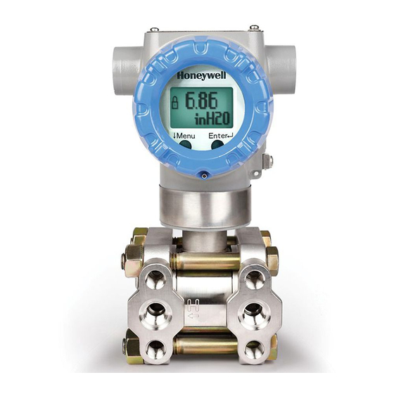
SmartLine Pressure Transmitter ST 700 Basic
Quick Start Safety Installation Guide
34-ST-25-57, Revision 2, November 2018
This document provides descriptions and
procedures for the Quick Installation of
Honeywell's ST 700 Basic SmartLine
Pressure Transmitter.
The ST 700 Basic SmartLine Pressure
Transmitter is available in a variety of
models for measuring Differential Pressure
(DP), Gauge Pressure (GP), and Absolute
Pressure (AP). For full details refer to the
manuals listed below for protocols, human
interface (HMI), Operation, Installation,
Configuration, Calibration, Maintenance,
Parts, Safety and Approvals etc. including
options.
Documentation
To access complete documentation, including language variants, scan
the QR code below using your smart phone/device or QR code scanner.
Go to the APP store for your free Smartphone QR scanner
Or you can follow the URL to access the online SmartLine HUB page.
The HUB page will contain direct links to open SmartLine product
documentation.
URL
https://hwll.co/SmartLineHUB
Installation
Evaluate the site selected for the Transmitter installation with respect to the process
system design specifications and Honeywell's published performance characteristics
for your particular model.
Temperature extremes can affect display quality. The display can become unreadable
at temperature extremes; however, this is only a temporary condition. The display will
again be readable when temperatures return to within operable limits.
Mounting the Transmitter
Transmitter models, except flush mounts and those with integral flanges, can be
attached to a two-inch (50 millimeter) vertical or horizontal pipe using Honeywell's
optional angle or flat mounting bracket; alternately you can use your own bracket.
Flush-mount models are attached directly to a process pipe or tank by a one-inch
weld nipple. Models with integral flanges are supported by the flange connection.
Typical Bracket mounted and Flange Mounted Installations
Figure 1:Mounting Brackets
March 2018
Copyrights, Notices and Trademarks
Copyright 2018 by Honeywell
Revision 2, November 2018
Trademarks
SmartLine, ST 700 are U.S. registered
trademarks of Honeywell Inc.
®
HART
is trademark of the FieldComm
Group™
QR Code
Quick Start Safety Installation Guide
Table of Contents
Installation .................................................................................................................. 1
Mounting the Transmitter ........................................................................................... 1
Conduit Entry Plugs and Adapters ............................................................................. 3
Wiring Connections and Power Up ............................................................................ 4
Explosion-Proof Conduit Seal .................................................................................... 4
Trim the Transmitter ................................................................................................... 4
Set the Jumpers For HART ........................................................................................ 5
Configuration Guide ................................................................................................... 5
Appendix A. PRODUCT CERTIFICATIONS .............................................................. 5
Hazardous Locations Certifications ............................................................................ 7
Control Drawing ......................................................................................................... 8
Table 1 - Conduit Entry Plugs .................................................................................... 3
Table 2 - Conduit Adapters ........................................................................................ 3
Table 3 - Jumper Settings .......................................................................................... 5
Table 4 - Standard Display Menu ............................................................................... 5
Figures
Figure 1:Mounting Brackets ....................................................................................... 1
Figure 2: Angle Mounting Bracket .............................................................................. 1
Figure 3: LGP and LAP models.................................................................................. 2
Figure 4: Rotating Transmitter Housing ..................................................................... 2
Figure 5: Using level to mount transmitter .................................................................. 2
Figure 6: Flange mounting ......................................................................................... 2
Figure 7: Flush Mounting ........................................................................................... 3
Figure 8: Remote Seal mounting................................................................................ 3
Figure 9: Electronic Housing Conduit Entries ............................................................. 3
Figure 10: Two-wire power/current loop ..................................................................... 4
Figure 11: Terminal Block and Grounding Screw location ......................................... 4
Figure 12: Jumper Location HART ............................................................................ 5
Bracket Mounting
Optional mounting bracket, see Figure 2
Existing mounting bracket, see Figure 3
Rotate the transmitter housing, see Figure 4
Level a transmitter with small absolute or differential pressure spans, see
Optional Mounting Bracket
Position the bracket on a 2-inch (50.8mm) and install "U" bolt around pipe and
through holes in bracket. Secure with nuts and lock washers provided.
Figure 2
Example - Angle mounting bracket secured to horizontal or vertical pipe.
Figure 2: Angle Mounting Bracket
Figure 5
1
Advertisement
Table of Contents

Related Manuals for Honeywell SmartLine ST700


Summary of Contents for Honeywell SmartLine ST700
-
Page 1: Table Of Contents
Secure with nuts and lock washers provided. Transmitter models, except flush mounts and those with integral flanges, can be attached to a two-inch (50 millimeter) vertical or horizontal pipe using Honeywell’s Figure 2 Example - Angle mounting bracket secured to horizontal or vertical pipe. -
Page 2: Figure 3: Lgp And Lap Models
Existing Mounting Bracket Rotating Transmitter Housing Align appropriate mounting holes in transmitter with holes in bracket and secure with Loosen set screw on outside neck of transmitter one full turn. Rotate Transmitter bolts and washers provided. housing in maximum of 180 degree increment in left or right direction from center to position you require and tighten set screw (1.46 to 1.68Nm/13 to 15lb-in). -
Page 3: Conduit Entry Plugs And Adapters
Flush Mounting Remote Seal Mounting To mount a flush mounted transmitter model, cut a hole for a 1-inch standard pipe in the Mount the transmitter at a remote distance determined by length of capillary tubing. tank or pipe where the transmitter is to be mounted. See Figure 7. -
Page 4: Wiring Connections And Power Up
For HART, use MCT or other HART See Figure 11, above, for parts locations. Communicator with applicable Honeywell DD's. Remove the end cap cover from the terminal block end of the Electronics While reading the transmitter’s output on a communication tool... -
Page 5: Set The Jumpers For Hart
Set the Jumpers For HART Setting Failsafe Direction and Write Protect Jumpers The ST 700 Basic SmartLine Pressure ATTENTION: Electrostatic Transmitter provides two jumpers to set Discharge (ESD) hazards. the desired failsafe action and Write Observe precautions for Protect option. handling electrostatic sensitive See, Figure 12... - Page 6 November 2018 Quick Start Installation Guide...
-
Page 7: Hazardous Locations Certifications
Hazardous Locations Certifications FIELD AMBIENT AGENCY TYPE OF PROTECTION PARA- TEMP (Ta) METERS Explosionproof: Class I, Division 1, Groups A, B, C, D; Dust Ignition Proof: T5: -50 ºC to 85ºC Class II, III, Division 1, Groups E, F, G; Note 1 T6: -50 ºC to 65ºC Class l, Zone 0/1, AEx d IIC Ga/Gb... -
Page 8: Control Drawing
Approval Certifications: (Continued) Control Drawing Notes: Operating Parameters: Voltage= 11 to 42 V DC Current= 4-20 mA Normal Intrinsically Safe Entity Parameters Analog/ DE/ HART Entity Values: Vmax= Ui = 30V Imax= Ii= 105mA Ci = 4.2nF Li =984 uH Pi =0.9W Transmitter with Terminal Block Revision E or Later Vmax = Ui =30V... - Page 9 Singapore, Honeywell Pte Ltd. Phone: +(65) 6580 3278. Fax: +(65) 6445-3033 Honeywell web site, it is up to the customer to determine the suitability of the product in the South Korea, Honeywell Korea Co Ltd. Phone:+(822)799 6114. Fax:+(822) 792 9015 application.
Need help?
Do you have a question about the SmartLine ST700 and is the answer not in the manual?
Questions and answers