Table of Contents
Advertisement
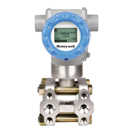
ST 800 and ST 700 Standard
SmartLine Pressure Transmitter
Quick Start Installation Guide
34-ST-25-36, Revision 5, December 2016
This document provides descriptions and
procedures for the Quick Installation of
Honeywell's family of SmartLine Pressure
Transmitters.
The SmartLine Pressure Transmitter is
available in a variety of models for
measuring Differential Pressure (DP),
Gauge Pressure (GP), and Absolute
Pressure (AP). For full details refer to the
manuals listed below for protocols,
human interface (HMI), Operation,
Installation, Configuration, Calibration,
Maintenance, Parts, Safety and
Approvals etc. including options.
Various other support documents are
available on the CD supplied with your
shipment. Documents in hardcopy can also
be ordered.
References
The following list identifies all documents that may be sources of reference for material
discussed in this publication.
ST 700 Basic SmartLine Transmitter Quick Start Guide
ST 800 SmartLine Transmitter User's Manual
ST 700 SmartLine Transmitter User's Manual
ST 800 SmartLine Transmitter HART/DE User Manual
ST 700 SmartLine Transmitter HART/DE User Manual
ST 800 Foundation Fieldbus Manual
ST 700 Foundation Fieldbus Manual
ST 800 / ST 700 FF Function Blocks Manual
ST 800 Safety Manual
MC Toolkit User Manual (MCT202)
MC Toolkit User Manual (MCT404)
Honeywell Process Solutions
Document Title
Copyrights, Notices and Trademarks
Copyright 2012 by Honeywell
Revision 4 –March 2016
Revision 5 –December 2016
Trademarks
SFC, SmartLine, ST 800 and ST 700 are
U.S. registered trademarks of Honeywell
Inc.
®
and FOUNDATION™ are
HART
trademarks of the FieldComm Group™
Document #
34-ST-25-57
34-ST-25-35
34-ST-25-44
34-ST-25-38
34-ST-25-47
34-ST-25-39
34-ST-25-48
34-ST-25-42
34-ST-25-37
34-ST-25-20
34-ST-25-50
Advertisement
Table of Contents

Related Manuals for Honeywell ST 800


Summary of Contents for Honeywell ST 800
- Page 1 ST 700 SmartLine Transmitter HART/DE User Manual 34-ST-25-47 ST 800 Foundation Fieldbus Manual 34-ST-25-39 ST 700 Foundation Fieldbus Manual 34-ST-25-48 ST 800 / ST 700 FF Function Blocks Manual 34-ST-25-42 ST 800 Safety Manual 34-ST-25-37 MC Toolkit User Manual (MCT202) 34-ST-25-20...
-
Page 2: Table Of Contents
Table 4 - Fieldbus Write Protect ................. 19 Table 5 – Basic Display Configuration (ST 700Std/ST800 only) ........ 20 Table 6 – Advanced Display Configuration (ST 800 only) .......... 21 Table 7 - Simple Display Menu (ST 700 Std only) ............22 Figures Figure 1: Mounting Brackets .................. -
Page 3: Installation
MOUNTING THE TRANSMITTER Transmitter models, except flush mounts and those with integral flanges, can be attached to a two-inch (50 millimeter) vertical or horizontal pipe using Honeywell’s optional angle or flat mounting bracket; alternately you can use your own bracket. -
Page 4: Bracket Mounting
SmartLine Pressure Transmitter Bracket Mounting Optional mounting bracket, see Figure 2 Existing mounting bracket, see Figure 3 Rotate the transmitter housing, see Figure 4 Level a transmitter with small absolute or differential pressure spans, see Figure 5. Optional Mounting Bracket Position the bracket on a 2-inch (50.8mm) and install “U”... -
Page 5: Existing Mounting Bracket
SmartLine Pressure Transmitter Existing Mounting Bracket Align appropriate mounting holes in transmitter with holes in bracket and secure with bolts and washers provided. Note: If the meter body is hexagonal, you must use the additional bracket supplied. If meter body is round, discard the bracket. Example –... -
Page 6: Rotating Transmitter Housing
SmartLine Pressure Transmitter Rotating Transmitter Housing Loosen set screw on outside neck of transmitter one full turn. Rotate Transmitter housing in maximum of 180 degree increment in left or right direction from center to position you require and tighten set screw (1.46 to 1.68Nm/13 to 15lb-in). Figure 4 Example –... -
Page 7: Leveling Transmitters With Small Absolute Or Differential Pressure Spans
SmartLine Pressure Transmitter Leveling Transmitters with Small Absolute or Differential Pressure Spans Mounting position of these transmitters is critical due to the smaller transmitter spans. To minimize these positional effects on calibration (zero shift), take the appropriate mounting precautions that follow for the given transmitter model. See Figure 5 for suggestions on how to level the transmitter using a spirit balance. -
Page 8: Flange Mounting
SmartLine Pressure Transmitter Flange Mounting To mount a flange mounted transmitter model, bolt the transmitter’s flange to the flange pipe on the wall of the tank. On insulated tanks, remove enough insulation to accommodate the flange extension. It is the End User’s responsibility to provide a flange gasket and mounting hardware that are suitable for the transmitter’s service condition. -
Page 9: Flush Mounting
SmartLine Pressure Transmitter Flush Mounting To mount a flush mounted transmitter model, cut a hole for a 1-inch standard pipe in the tank or pipe where the transmitter is to be mounted. See Figure 7 Weld the 1-inch mounting sleeve to the wall of the tank or to the hole cut on the pipe. Insert the meter body of the transmitter into the mounting sleeve and secure with the locking bolt. -
Page 10: Remote Seal Mounting
SmartLine Pressure Transmitter Remote Seal Mounting Mount the transmitter at a remote distance determined by length of capillary tubing. Note: The combination of tank vacuum and high pressure capillary head effect should not exceed 9psi (300mm Hg) absolute. On insulated tanks, remove enough insulation to accommodate the mounting sleeve. Figure 8 Example –... -
Page 11: Conduit Entry Plugs And Adapters
SmartLine Pressure Transmitter CONDUIT ENTRY PLUGS AND ADAPTERS Procedures It is the User/Installer’s responsibility to install the Transmitters in accordance with national and local code requirements. Conduit entry plugs and adapters shall be suitable for the environment, shall be certified for the hazardous location when required and acceptable to the authority having jurisdiction for the plant. -
Page 12: Table 2 - Conduit Adapters
SmartLine Pressure Transmitter Table 2 - Conduit Adapters Step Action Remove the protective plastic cap from the threaded conduit entry. To ensure the environmental ingress rating on tapered threads (NPT), a non-hardening thread sealant may be used. Thread the appropriate size adapter (M20 or ½ NPT) into the conduit entry opening Tighten adapters according to the following table. -
Page 13: Wiring Connections And Power Up
SmartLine Pressure Transmitter WIRING CONNECTIONS AND POWER UP Summary The transmitter is designed to operate in a two-wire power/current loop with loop resistance and power supply voltage within the operating range shown in Figure 10 Loop wiring is connected to the transmitter by simply attaching the positive (+) and negative (–) loop wires to the positive (+) and negative (–) SIGNAL screw terminals on the terminal block in the transmitter’s electronics housing shown in Figure 11. -
Page 14: Wiring Variations
Wiring must comply with local codes, regulations and ordinances. Grounding may be required to meet various approval body certification, for example CE conformity. Refer to the SmartLine Transmitter User’s Manual, Documents # 34-ST-25-35 (ST 800) or 34-ST-25-44 (ST 700) for details. Quick Start Installation Guide December 2016... -
Page 15: Explosion-Proof Conduit Seal
SmartLine Pressure Transmitter EXPLOSION-PROOF CONDUIT SEAL When installed as explosion proof in a Division 1 Hazardous Location, keep covers tight while the Transmitter is energized. Disconnect power to the Transmitter in the non-hazardous area prior to removing end caps for service. When installed as non-incendive equipment in a Division 2 hazardous location, disconnect power to the Transmitter in the non-hazardous area, or determine that the location is non-hazardous before disconnecting or connecting the... -
Page 16: Trim The Transmitter
For DE transmitter use SFC, SCT, or MCT. For Hart, use MCT or other Hart Communicator with applicable Honeywell DD's. For Fieldbus, use NI FBUS tools with applicable Honeywell DD's. While reading the transmitter’s output on a communication tool or a voltmeter, position the transmitter so the output reading is at or near zero, and then completely tighten the mounting bolts. -
Page 17: Set The Jumpers For Hart/De
SmartLine Pressure Transmitter SET THE JUMPERS FOR HART/DE Setting Failsafe Direction and Write Protect Jumpers The SmartLine Pressure Transmitter (DE or HART) provides two jumpers ATTENTION: Electrostatic to set the desired failsafe action and Discharge (ESD) hazards. Write Protect option. See Observe precautions for handling electrostatic sensitive The top jumper on the electronics... -
Page 18: Table 3 - Jumper Settings
SmartLine Pressure Transmitter Figure 12: Jumper Location HART/DE Table 3 - Jumper Settings Jumper Description Settings Failsafe = UP (High) Write Protect = OFF (Not Protected) Failsafe = DOWN (Low) Write Protect = OFF (Not Protected) Failsafe = UP (High) Write Protect = ON (Protected) Failsafe = DOWN (Low) Write Protect = ON (Protected) -
Page 19: Write Protect Jumper On Foundation Fieldbus (Ff)
SmartLine Pressure Transmitter WRITE PROTECT JUMPER ON FOUNDATION FIELDBUS (FF) On Foundation Fieldbus transmitters there is no Failsafe jumper selection but there is a Write Protect jumper. The bottom jumper sets the Write Protect. The default setting is OFF (Unprotected). When set to the ON (Protected) position, changes to configuration parameters cannot be written to the transmitter. -
Page 20: Configuration Guide
Basic LED Display: 2 lines, 16 characters (ST 700 Std/800 only) - Table 5 Advanced LED Display: Multi-line display (ST 800 only) - Table 6 Simple LED Display: 2 lines, 6 character (ST 700 Std only) - Table 7 Table 5 –... -
Page 21: Table 6 - Advanced Display Configuration (St 800 Only)
SmartLine Pressure Transmitter Table 6 – Advanced Display Configuration (ST 800 only) ST 800 Only <Return> <Return> Critical Active Diags Diagnostics Non-Critical <Return> Meterbody Active Diags Elec Module Analog Out mode Meterbody Comm Zero Correct Span Correct Supply Voltage Primary PV... -
Page 22: Table 7 - Simple Display Menu (St 700 Std Only)
SmartLine Pressure Transmitter Table 7 - Simple Display Menu (ST 700 Std only) UNITS Visible for all PV except Set Pressure Units Flow FLUNITS Visible where PV is Flow Set Flow Units SCLLOW Scaling Low Visible where PV is Flow SCLHIG Scaling High ENTLRV / ENTURV... - Page 23 Authorized Distributor, contact one of the offices below. ASIA PACIFIC (TAC) hfs-tac-support@honeywell.com Australia Honeywell Limited, Phone: +(61) 7-3846 1255, FAX: +(61) 7-3840 6481 Toll Free 1300-36-39-36, Toll Free Fax: 1300-36-04-70 China – PRC – Shanghai, Honeywell China Inc. Phone: (86-21) 5257-4568, Fax: (86-21) 6237-2826 Singapore, Honeywell Pte Ltd.
- Page 24 However, we assume no responsibility for its use. While we provide application assistance personally, through our literature and the Honeywell web site, it is up to the customer to determine the suitability of the product in the application.
Need help?
Do you have a question about the ST 800 and is the answer not in the manual?
Questions and answers