Sign In
Upload
Download
Table of Contents
Contents
Add to my manuals
Delete from my manuals
Share
URL of this page:
HTML Link:
Bookmark this page
Add
Manual will be automatically added to "My Manuals"
Print this page
×
Bookmark added
×
Added to my manuals
Manuals
Brands
Honeywell Manuals
Transmitter
STT25M
Operator's manual
Honeywell STT25M Operator's Manual
Stt 3000-series stt250 smart temperature transmitter
Hide thumbs
1
Table Of Contents
2
3
4
5
6
7
8
9
10
11
12
13
14
15
16
17
18
19
20
21
22
23
24
25
26
27
28
29
30
31
32
33
34
35
36
37
38
39
40
page
of
40
Go
/
40
Contents
Table of Contents
Troubleshooting
Bookmarks
Table of Contents
Table of Contents
1 Overview
Introduction
2 Technical Specifications
Environmental Conditions
Physical Specifications
Figure 1 : Operating Areas
3 Theory of Operation
Basic Operation
Configuration Tools
Smart Field Communicator (SFC)
HART Communicator (Model 275)
Smartline Configuration Toolkit (SCT)
4 Bench Check Installation/Commissioning
Equipment
Figure 2: Bench Check Wiring Connections
Installation
Unpacking
Grounding and Shielding Techniques
Stt250 Configuration
Analog Output Configuration (Based on STS103)
Figure 3: Output Sensor Wiring Connections
Figure 4: Flow Chart for Analog and de Configuration
DE Digital Output Configuration
Figure 4-1: Specific Flow Chart for de Configuration
HART Configuration
Figure 5: Flow Chart for HART Configuration
Mounting
DIN Rail Mounting
Mounting Module in Housing
Figure 6: DIN Rail Mounting
Figure 7: Wall Mounting Dimensions
Figure 8: Pipe Mounting Dimensions
Figure 9: Spring Loading and Sensor Assembly
Figure 10: Aluminium Direct Head Mount Housing Dimensions
Figure 11: Plastic Direct Head Mount Housing Dimensions
Figure 12: Cast Iron Direct Head Mount Housing Dimensions
Commissioning
Figure 13: Stainless Steel Direct Head Mount Housing Dimensions
Start up
5 Maintenance/Troubleshooting
Maintenance
Troubleshooting
Troubleshooting with SFC
Troubleshooting with HART Communicator
Recommended Parts
Wiring and Installation Drawings Numbers
6 Indication Meters
Introduction
Connection Information
Figure 14: Meters Connections
Installation/Commissioning
Transmitter Operating in 6 Byte Output Mode
Transmitter Operating in 4 Byte Digital Output or in 4-20 Ma Analog Mode
Transmitter Operating in 4-20 Ma Analog Output Mode
Diagnostic and Troubleshooting
Analog Meter
Smart Meter
Figure 15: Horizontal Style Bargraph
Ma Analog Mode Calibration of Smart Meter
Instruction
Appendix A Transient Protector Installation
A.1 O Verview
Electrical Characteristics
Features and Benefits
Overview
A.4 I Nstallation P Rocedure
Installation Procedure
A.5 W Iring R Eference
Figure A-1: Typical Wiring of Transient Protector to STT250 Transmitter
Wiring Reference
Advertisement
Quick Links
1
Overview
2
Introduction
3
Physical Specifications
4
Technical Specifications
Download this manual
STT 3000 - Series STT250
Smart Temperature Transmitter
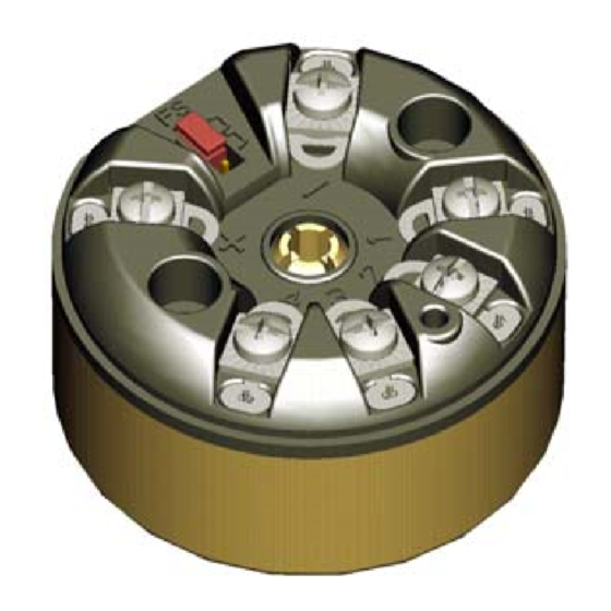
Models STT25D, STT25H, STT25M
Operator Manual
Product of France
Issue 6 - 02/00
EN1I-6190
Table of
Contents
Previous
Page
Next
Page
1
2
3
4
5
Advertisement
Table of Contents
Troubleshooting
MAINTENANCE/TROUBLESHOOTING
22
Troubleshooting with HART communicator
25
DIAGNOSTIC AND TROUBLESHOOTING
32
Need help?
Do you have a question about the STT25M and is the answer not in the manual?
Ask a question
Questions and answers
Related Manuals for Honeywell STT25M
Transmitter Honeywell stt850 SMARTLINE User Manual
Temperature transmitter (94 pages)
Transmitter Honeywell STT850 Quick Start Manual
Smartline temperature transmitter (27 pages)
Transmitter Honeywell STT850 Quick Start Manual
(8 pages)
Transmitter Honeywell SmartLine STT850 Quick Start Manual
Temperature transmitter (11 pages)
Transmitter Honeywell STT25D Operator's Manual
Stt 3000-series stt250 smart temperature transmitter (40 pages)
Transmitter Honeywell STT25H Operator's Manual
Stt 3000-series stt250 smart temperature transmitter (40 pages)
Transmitter Honeywell STT850 Series User Manual
Smartline temperature transmitters (118 pages)
Transmitter Honeywell STT750 Quick Start Installation Manual
Smartline temperature transmitter (20 pages)
Transmitter Honeywell STT750 SmartLine User Manual
Temperature transmitter (72 pages)
Transmitter Honeywell SmartLine STT750 Technical Information
Temperature transmitter (19 pages)
Transmitter honeywell STT700 SmartLine User Manual
Temperature transmitter (62 pages)
Transmitter Honeywell SmartLine STT700 HART Quick Start Installation Manual
Temperature transmitter (14 pages)
Transmitter Honeywell SmartLine STT700 HART User Manual
Stt700 series hart/de option (114 pages)
Transmitter Honeywell HART STT700 Safety Manual
Smartline temperature transmitter (16 pages)
Transmitter Honeywell STT700 STT700 User Manual
Temperature transmitter (64 pages)
Transmitter Honeywell ST 700 User Manual
Smartline pressure transmitters (82 pages)
Summarization of Contents
OVERVIEW
1.1 INTRODUCTION
Provides a general overview of the STT250 Smart Temperature Transmitter.
TECHNICAL SPECIFICATIONS
2.1 ENVIRONMENTAL CONDITIONS
Details the operating and storage conditions for the transmitter.
2.1.1 Physical Specifications
Describes the physical dimensions and variations of the STT250.
THEORY OF OPERATION
3.1 BASIC OPERATION
Explains the fundamental working principles of the STT250 transmitter.
3.2 CONFIGURATION TOOLS
Outlines the tools used for configuring the transmitter, including SFC, HART, and SCT.
3.2.1 Smart Field Communicator (SFC)
Details the functionality and supported commands of the SFC.
3.2.2 HART Communicator (model 275)
Explains communication via the HART protocol using the model 275 communicator.
3.2.3 Smartline Configuration Toolkit (SCT)
Describes the use of the SCT for configuring DE protocol transmitters.
BENCH CHECK INSTALLATION/COMMISSIONING
4.1 UNPACKING
Instructions for unpacking and verifying the contents of the STT250.
4.2 EQUIPMENT
Lists the necessary equipment for bench testing the transmitter.
4.3 INSTALLATION
Provides guidance on connecting equipment for bench installation.
4.4 GROUNDING AND SHIELDING TECHNIQUES
Covers methods for proper grounding and shielding to prevent noise.
4.5 STT250 CONFIGURATION
Steps and procedures for configuring the STT250 transmitter settings.
4.5.1 Analog Output Configuration (based on STS103)
Guides through configuring the analog output using the SFC.
4.5.2 DE Digital Output Configuration
Details the process of configuring the transmitter for digital DE output.
4.5.3 HART Configuration
Instructions for configuring the transmitter using the HART protocol.
4.6 MOUNTING
Information and methods for mounting the STT250 transmitter.
4.6.1 DIN Rail Mounting
Specific steps for mounting the STT250 on a DIN rail.
4.6.2 Mounting Module in Housing
Describes different housing options for mounting the transmitter.
4.7 COMMISSIONING
Procedures for verifying and setting up the transmitter after installation.
4.8 START UP
Steps for safely starting up and testing the transmitter in operation.
MAINTENANCE/TROUBLESHOOTING
5.1 MAINTENANCE
Guidelines for routine maintenance of the STT250 transmitter.
5.2 TROUBLESHOOTING
Procedures and common issues for diagnosing and resolving problems.
5.2.1 Troubleshooting with SFC
Troubleshooting the STT250 loop using the Smart Field Communicator (SFC).
5.2.2 Troubleshooting with HART communicator
Troubleshooting the STT250 loop using a HART communicator.
5.3 RECOMMENDED PARTS
A list of recommended spare and replacement parts for the STT250.
5.4 WIRING AND INSTALLATION DRAWINGS NUMBERS
References to specific drawing numbers for wiring and installation.
INDICATION METERS
6.1 INTRODUCTION
Overview of integral meters supplied with the transmitter.
6.2 CONNECTION INFORMATION
Details on how to wire the meters in the loop.
6.3 INSTALLATION/COMMISSIONING
Steps for installing and commissioning the indication meters.
6.3.1 Transmitter Operating in 6 Byte Output Mode
Configuration for 6-byte digital DE output mode for meters.
6.3.2 Transmitter Operating in 4 Byte Digital Output or in 4-20 mA Analog Mode
Configuration for 4-byte digital DE or 4-20 mA analog modes.
6.3.3 Transmitter Operating in 4-20 mA Analog Output Mode
Specifics for configuring meters with 4-20 mA analog output.
6.4 DIAGNOSTIC AND TROUBLESHOOTING
How to diagnose and troubleshoot issues with indication meters.
6.4.1 Analog Meter
Troubleshooting specific to the analog meter.
6.4.2 Smart Meter
Diagnosis and troubleshooting for the Smart Meter.
6.4.2.1 Failed self test
Actions to take if the Smart Meter's self-test fails.
6.4.2.2 Meter Fault Conditions
Common fault conditions and their corrective actions for Smart Meters.
6.4.3 4-20 mA Analog Mode Calibration of Smart Meter
Procedure for calibrating the Smart Meter for 4-20 mA analog signals.
APPENDIX A TRANSIENT PROTECTOR INSTALLATION INSTRUCTION
A.1 OVERVIEW
Introduction to Honeywell's transient protectors for STT 3000 transmitters.
A.2 FEATURES AND BENEFITS
Describes the protective features and advantages of the transient protectors.
A.3 ELECTRICAL CHARACTERISTICS
Lists the electrical specifications of the transient protectors.
A.4 INSTALLATION PROCEDURE
Step-by-step guide for installing the transient protector.
A.5 WIRING REFERENCE
Provides a typical wiring diagram for transient protector connections.
Table of Contents
Save PDF
Print
Rename the bookmark
Delete bookmark?
Delete from my manuals?
Login
Sign In
OR
Sign in with Facebook
Sign in with Google
Upload manual
Upload from disk
Upload from URL
Need help?
Do you have a question about the STT25M and is the answer not in the manual?
Questions and answers