Honeywell STT850 Quick Start Manual
Hide thumbs
Also See for STT850:
- User manual (94 pages) ,
- Quick start manual (27 pages) ,
- Quick start manual (11 pages)
Table of Contents
Advertisement
Quick Links
STT850/750 SmartLine Temperature Transmitter
Quick Start Guide
34-TT-25-04, Revision 8, January 2020
This document provides descriptions
and procedures for the Quick
Installation of Honeywell's family of
SmartLine Temperature Transmitters.
The SmartLine Temperature
Transmitter is available in a variety of
models for measuring Ohms, mV and
temperature from RTD's and
thermocouples.
For full details refer to the manuals
listed below for Protocols, User
Interface (HMI) Operation, Installation,
Configuration, Calibration,
Maintenance, Parts, Safety and
Approvals etc. including options.
Documentation
To access complete documentation, including language variants, scan
the QR code below using your smart phone/device or QR code scanner.
Go to the APP store for your free Smartphone QR scanner
Or you can follow the URL to access the online SmartLine HUB page.
The HUB page will contain direct links to open SmartLine product
documentation.
URL
QR Code
https://hwll.co/SmartLineHUB
Note
This is a generic Quick Start Guide for both STT850 and STT750
transmitters. Please note the following do not apply to the STT750:
Foundation Fieldbus, DE, Dual Inputs, Advanced Display, Advanced
Diagnostic, MID and Marine approvals.
nstallation
I
Evaluate the site selected for the Transmitter installation with respect to
the process system design specifications and Honeywell's published
performance characteristics for your particular model.
Temperature extremes can affect display quality. The display can become
unreadable at temperature extremes; however, this is only a temporary
condition. The display will again be readable when temperatures return to
within operable limits.
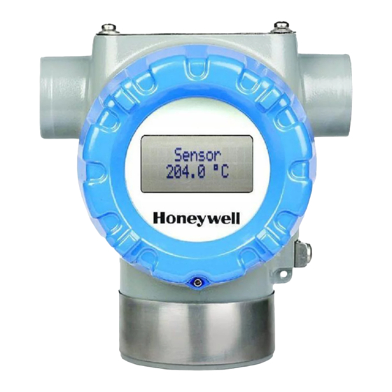
Features and options
The STT850 and STT750 are packaged in one major assembly: the
Electronics Housing.
The elements in the Electronic Housing are connected to the process
sensors, measure the process variables, respond to setup commands
and execute the software and protocol for the different temperature
measurement types.
Figure 1
shows the assemblies in the Electronics
Housing with available options.
Figure 1 - Electronics Housing Components
An optional 3-button assembly is located under the nameplate and provides
a user interface and operation capability without opening the transmitter to
set up and make adjustments to the transmitter.
Copyrights, Notices and
Trademarks
Copyright 2020 by Honeywell
Revision 8, January 2020
Trademarks
SFC, SmartLine, STT850 are
U.S. registered trademarks of
Honeywell Inc.
HART® and FOUNDATION
™
Trademarks of FieldComm
Group™
STT850/750 Quick Start Guide
Table of Contents
URL ........................................................................................................... 1
Note ........................................................................................................... 1
Installation ................................................................................................. 1
Features and options ................................................................................ 1
Mounting the Transmitter .......................................................................... 1
Bracket Mounting ................................................................................ 2
Optional Mounting Bracket ................................................................. 2
Conduit Entry Plugs and Adapters ............................................................ 2
Wiring Connections and Power Up ........................................................... 2
Wiring Variations ................................................................................. 3
Input Sensor Wiring ............................................................................ 3
Digital Output Wiring ........................................................................... 4
Setting Failsafe Direction and Write Protect Jumpers ........................ 4
Write Protect Jumper on Foundation Fieldbus (FF) ................................. 5
Figure 1 - Electronics Housing Components ........................................... 1
Figure 2 -STT with adapter housing - Horizontal Wall Mounting ............. 1
Figure 3 - Pipe Mount, Vertical ................................................................. 1
Figure 4 - Pipe Mount with adapter housing - Horizontal & Vertical ......... 2
Figure 5: Flat and Angle Mounting Brackets secured to Horizontal or
Vertical Pipe .............................................................................................. 2
Figure 6: Electronic Housing Conduit Entries ........................................... 2
Figure 7: HART and DE Transmitter Operating Ranges .......................... 2
Figure 8: Transmitter 9-Screw Terminal Board and Grounding Screw .... 3
Figure 9: HART/DE/FF Single Input Wiring Diagram ............................... 3
Figure 10: DE Dual Input Wiring Diagram ................................................ 3
Figure 11: HART/FF - Dual Input Wiring Diagram ................................... 3
Figure 12: HART/FF Dual Input Wiring Diagram, mixed sensors ............ 3
Figure 13: Digital Output Connections for mA Load (HART only) ............ 4
Figure 14: Digital Output Connections for PLC Counting Input (HART
only) ........................................................................................................... 4
Figure 15: Jumper Location HART/DE ..................................................... 4
Figure 16: Jumper Settings ....................................................................... 4
Figure 17: Fieldbus Write Protect ............................................................. 5
Mounting the Transmitter
Transmitter models can be attached to a two-inch (50 millimeter) vertical
or horizontal pipe using Honeywell's optional angle; alternately you can
use your own bracket.
Honeywell's optional wall mounting bracket is also shown below:
For Housing with Adaptor refer to Honeywell drawings 50095917 (Pipe
mount) and 50095918 (Wall mount) for detailed mounting specifications.
For Housing without adaptor refer to Honeywell drawings 32306827 (No-
Adaptor, Pipe mount) and 32306828 (No-adaptor, Wall mount).
TRANSMITTER ENCLOSURE CAN BE ROTATED A TOTAL OF 90O
FROM THE STANDARD MOUNTING POSITION
Figure 2 -STT with adapter housing - Horizontal Wall Mounting
Figure 3 - Pipe Mount, Vertical
1
Advertisement
Table of Contents

Related Manuals for Honeywell STT850


Summary of Contents for Honeywell STT850
- Page 1 Figure 17: Fieldbus Write Protect ............. 5 Note Mounting the Transmitter This is a generic Quick Start Guide for both STT850 and STT750 Transmitter models can be attached to a two-inch (50 millimeter) vertical transmitters. Please note the following do not apply to the STT750: or horizontal pipe using Honeywell’s optional angle;...
- Page 2 Note that the Transmitter is not polarity-sensitive. Figure 6: Electronic Housing Conduit Entries Note. No plugs come installed in the housings. All housings come with temporary plastic dust protectors (red) installed and are not certified for use in any installation. STT850/750 Quick Start Guide...
- Page 3 For External C/J compensation, the first input is a thermocouple type and the second input is a 3-wire PT100 ohm RTD The STT850 can have different sensor types on its inputs for split range or averaging applications Figure 10: DE Dual Input Wiring Diagram...
- Page 4 When set to the OFF (Un-protected) position, Changed configuration Screw on the end cap and tighten parameters can be written to the the end-cap lock. Turn ON Figure 16: Jumper Settings transmitter. Transmitter power. STT850/750 Quick Start Guide...
- Page 5 On Foundation Fieldbus transmitters there is no Failsafe jumper selection but there is a A1. Safety Instrumented Systems (SIS) Installations Write Protect jumper. For Safety Certified Installations, please refer to STT850/750 Safety Manual The bottom jumper sets the Write Protect. The default setting is OFF (Un-protected). #34-TT-25-05 for installation procedure and system requirements.
- Page 6 OIML R117.1 Edition 2007 (E), and EN 12405-1+A2 Edition 2006. (not STT750) Applicable to Pt100 sensor only. MARINE TYPE Lloyd’s Register Certificate Number: 16/60011 APPROVAL Environmental categories ENV1, ENV2, ENV3 and ENV5 as defined in Lloyd’s Register Test Specification No. 1, February 2015 (not STT750) STT850/750 Quick Start Guide...
- Page 7 Consult the manufacturer for dimensional information on the flameproof joints for repair. Painted surface of the STT850 may store electrostatic charge and become a source of ignition in applications with a low relative humidity less than approximately30% relative humidity where the painted surface is relatively free of surface contamination such as dirt, dust or oil.
- Page 8 While we provide application assistance personally, through our literature and the 9015 Honeywell web site, it is up to the customer to determine the suitability of the product in EMEA, Phone: + 80012026455 or +44 (0)1202645583. FAX: +44 (0) 1344 655554 the application.
Need help?
Do you have a question about the STT850 and is the answer not in the manual?
Questions and answers