Rigol DS1074B Service Manual
Ds1000b series digital oscilloscope
Hide thumbs
Also See for DS1074B:
- User manual (172 pages) ,
- Programming manual (152 pages) ,
- Quick manual (18 pages)

Related Manuals for Rigol DS1074B


Summary of Contents for Rigol DS1074B
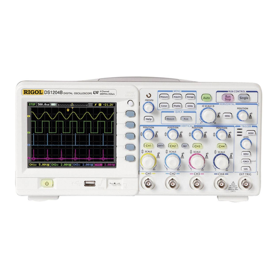
- Page 1 RIGOL Service Guide DS1000B Series Digital Oscilloscope DS1074B, DS1104B, DS1204B Dec. 2014 RIGOL Technologies, Inc.
-
Page 3: Guaranty And Declaration
Notices RIGOL products are covered by P.R.C. and foreign patents, issued and pending. RIGOL reserves the right to modify or change parts of or all the specifications and pricing policies at company’s sole decision. Information in this publication replaces all previously corresponding material. -
Page 4: General Safety Summary
Do not touch exposed junctions and components when the unit is powered. Do Not Operate With Suspected Failures. If you suspect damage occurs to the instrument, have it inspected by RIGOL authorized personnel before further operations. Any maintenance, adjustment or... - Page 5 RIGOL replacement especially to circuits or accessories must be performed by RIGOL authorized personnel. Keep Well Ventilation. Inadequate ventilation may cause an increase of instrument temperature which would cause damage to the device. So please keep the instrument well ventilated and inspect the intake and fan regularly.
- Page 6 RIGOL stresses are variable; for that reason, the transient withstand capability of the equipment is made known to the user. WARNING IEC Measurement Category I. The input terminals may be connected to circuit terminal in IEC Category I installations for voltages up to 300 VAC. To avoid the danger of electric shock, do not connect the inputs to circuit’s voltages above 300...
-
Page 7: Safety Terms And Symbols
RIGOL Safety Terms and Symbols Terms Used in this Manual. These terms may appear in this manual: WARNING Warning statements indicate conditions or practices that could result in injury or loss of life. CAUTION Caution statements indicate conditions or practices that could result in damage to this product or other property. -
Page 8: Allgemeine Sicherheits Informationen
RIGOL Allgemeine Sicherheits Informationen Überprüfen Sie diefolgenden Sicherheitshinweise sorgfältigumPersonenschädenoderSchäden am Gerätundan damit verbundenen weiteren Gerätenzu vermeiden. Zur Vermeidung vonGefahren, nutzen Sie bitte das Gerät nur so, wiein diesem Handbuchangegeben. Um Feuer oder Verletzungen zu vermeiden, verwenden Sie ein ordnungsgemäßes Netzkabel. - Page 9 Wenn Sie am Gerät einen Defekt vermuten, sorgen Sie dafür, bevor Sie das Gerät wieder betreiben, dass eine Untersuchung durch RIGOL autorisiertem Personal durchgeführt wird. Jedwede Wartung, Einstellarbeiten oder Austausch von Teilen am Gerät, sowie am Zubehör dürfen nur von RIGOL autorisiertem Personal durchgeführt werden. Belüftung sicherstellen.
-
Page 10: Sicherheits Begriffe Und Symbole
RIGOL Sicherheits Begriffe und Symbole Begriffe in diesem Guide. Diese Begriffe können in diesem Handbuch auftauchen: WARNING Die Kennzeichnung WARNING beschreibt Gefahrenquellen die leibliche Schäden oder den Tod von Personen zur Folge haben können. CAUTION Die Kennzeichnung Caution (Vorsicht) beschreibt Gefahrenquellen die Schäden am Gerät hervorrufen können. -
Page 11: Document Overview
RIGOL Document Overview Chapter 1 Specifications List the specifications and general specifications of DS1000B series. Chapter 2 To Prepare for Use Introduce the preparations should be done before using the oscilloscope. Chapter 3 Performance Test Introduce how to execute the performance tests of DS1000B series to understand its current performance status. -
Page 12: Table Of Contents
RIGOL Contents Contents Guaranty and Declaration ................I General Safety Summary ................II Safety Terms and Symbols ................ V Allgemeine Sicherheits Informationen ............. VI Sicherheits Begriffe und Symbole ............VIII Document Overview ................. IX Chapter 1 Specifications ..............1-1 Specifications ..................1-2 General Specifications ................ - Page 13 Contents RIGOL To Disassemble and Assemble the Keyboard ..........5-10 To Disassemble and Assemble the Main Board .......... 5-11 Chapter 6 Troubleshooting ..............6-1 Chapter 7 Replaceable Parts..............7-1 Chapter 8 Service&Support ..............8-1 Warranty ....................8-2 Worry-free Support Plan ................8-3 General Care and Cleaning ...............
- Page 14 RIGOL Contents Figures Figure 2-1 To Connect the power cord .............. 2-3 Figure 2-2 Power-on Inspection ............... 2-3 Figure 2-3 BNC Interface Connection ..............2-4 Figure 2-4 Circuit Under Test Connection ............2-4 Figure 2-5 To Set the Probe Switch and Attenuation Coefficient ......2-5 Figure 2-6 To Connect the Probe Compensator ..........
- Page 15 Contents RIGOL Tables Table 2-1 Auto Setting Items ................2-7 Table 3-1 Setting Value of the Oscilloscope under Test ........3-11 Table 3-2 Horizontal Time Base Setting Value for the Oscilloscope under Test ..3-17 Table 7-1 Replaceable Parts List ..............7-1...
-
Page 17: Chapter 1 Specifications
Chapter 1 Specifications RIGOL Chapter 1 Specifications All the specifications apply to the DS1000B series oscilloscopes unless otherwise noted. To meet these specifications, the oscilloscope should meet the following two conditions. The instrument must have been operating continuously for at least 30 minutes ... -
Page 18: Specifications
8k sample points when the horizontal timebase is 50ns/div or higher Each channel: 8k sample points Scan Speed Range 1ns/div~50s/div, DS1204B (S/div) 2ns/div~50s/div, DS1104B 5ns/div~50s/div, DS1074B 1-2-5 Sequence Sample Rate and ±50ppm (any time interval that is ≥1ms) Delay Time Accuracy Vertical A/D Converter... - Page 19 Chapter 1 Specifications RIGOL 100MHz (DS1104B) 200MHz (DS1204B) Single-shot Bandwidth 70MHz (DS1074B) 100MHz (DS1104B) 200MHz (DS1204B) Selectable Analog 20MHz (typical) Bandwidth Limit Lower Frequency ≤5Hz (at BNC) Response (AC -3dB) Rise Time (Typical at <1.75ns, <3.5ns, <5ns, BNC) On 200MHz, 100MHz, 70MHz respectively DC Gain Accuracy 2mV/div to 5mV/div: ±4% (Normal or Average...
-
Page 20: Edge Trigger
[1] Half channel indicates selecting one of CH1 and CH2, or one of CH3 and CH4. [2] This is the highest specification for the highest model. The specific equivalent sample rate of each model is as follows. DS1204B: 50GSa/s DS1104B: 25GSa/s DS1074B: 10GSa/s DS1000B Service Guide... -
Page 21: General Specifications
Chapter 1 Specifications RIGOL General Specifications Display Display Type 5.7 inch (145 mm diagonal line) TFT LCD Display Resolution 320 horizontal × RGB × 240 vertical pixels Display Color 64k color Contrast (Typical) 150:1 Backlight Brightness (Typical) 300 nit Probe Compensator Output... -
Page 23: Chapter 2 To Prepare For Use
Chapter 2 To Prepare for Use RIGOL Chapter 2 To Prepare for Use Topics of this chapter: General Inspection Power-on Inspection To Connect the Probes Probe Compensation Auto Setting of Waveform Display DS1000B Sevice Guide... -
Page 24: General Inspection
RIGOL would not be responsible for free maintenance/rework or replacement of the unit. 2. Inspect the instrument In case of any damage, or defect, or failure, notify your RIGOL sales representative. 3. Check the accessories Please check the accessories according to the packing lists. If the accessories are incomplete or damaged, please contact your RIGOL sales representative. -
Page 25: Power-On Inspection
Chapter 2 To Prepare for Use RIGOL Power-on Inspection The operating voltage range and frequency range for DS1000B series digital oscilloscope are 100 to 240VAC and 45 to 440Hz, respectively. Please connect the power cord to the power socket at the rear side of the oscilloscope and then connect the power cord to AC power supply. -
Page 26: To Connect The Probes
RIGOL Chapter 2 To Prepare for Use To Connect the Probes DS1000B series digital oscilloscope provides four channel inputs and an external trigger input. Please take the following steps to connect the probes. 1. Connect the BNC connector of the probe to the channel input or external trigger interface. -
Page 27: Probe Compensation
Chapter 2 To Prepare for Use RIGOL Probe Compensation Probe compensation should be performed when the probe is connected to a input channel for the first time to match the probe with the input channel. Non-compensated probe or improperly compensated probe would cause measurement error. -
Page 28: Figure 2-7 Waveform Compensation
RIGOL Chapter 2 To Prepare for Use Over compensated Correctly compensated Under compensated Figure 2-7 Waveform Compensation 4. If necessary, use a non-metallic screwdriver to adjust the variable capacitor on the probe until the waveform displayed is as the “Correctly compensated” in the figure above. -
Page 29: Auto Setting Of Waveform Display
Chapter 2 To Prepare for Use RIGOL Auto Setting of Waveform Display DS1000B series digital oscilloscope provides the auto setting function. The oscilloacope can adjust the voltage ratio, time base and trigger mode automatically according to the input signal to realize optimum waveform display. To use the auto setting function, the frequency of the input signal should be greater than or equal to 50Hz and the duty cycle should be greater than 1%. -
Page 31: Chapter 3 Performance Test
Chapter 3 Performance Test RIGOL Chapter 3 Performance Test Topics of this chapter: Interfaces Test USB Host Interface Test USB Device Interface Test LAN Interface Test Specification Test Impedance Test DC Gain Accuracy Test Bandwidth Test Bandwidth Limit Test... -
Page 32: Interface Test
RIGOL Chapter 3 Performance Test Interface Test USB Host Interface Test Purpose: Test whether the USB Host interface works normally using a USB storage device. Tools: A set of DS1000B series digital oscilloscope A USB storage device Steps: 1. -
Page 33: Figure 3-3 Usb Storage Device Connection Succeeds
Chapter 3 Performance Test RIGOL Figure 3-3 USB Storage Device Connection Succeeds 3. If an update program of the oscilloscope is stored in the USB storage device, the oscilloscope detects the program automatically and a prompt will be dispalyed to ask you whether to update the oscilloscope;... -
Page 34: Usb Device Interface Test
Figure 3-5 USB Device Interface Connection Fails For the newest version of Ultrascope for DS1000B Series, please download it from RIGOL official website (www.rigolna.com). DS1000B Service Guide... -
Page 35: Lan Interface Test
Chapter 3 Performance Test RIGOL LAN Interface Test Propose: Test whether the LAN interface works normally using IE explorer. Tools: A set of DS1000B series digital oscilloscope A PC with LAN interface A standard network cable Steps: 1. -
Page 36: Specification Test
Chapter 3 Performance Test Specification Test DS1000B series digital oscilloscope includes 3 models (DS1074B, DS1104B and DS1204B). In this manual, DS1204B is taken as an example to illustrate the specification test methods. Unless otherwise noted, the introductions are applicable to the other models. -
Page 37: Impedance Test
Chapter 3 Performance Test RIGOL Impedance Test Specification: Input Impedance Analog Channel (CH1 to CH4) 1 MΩ: 0.98 MΩ to 1.02 MΩ Test Procedures: 1. Impedance test of CH1 to CH4 Connect the active signal terminal of Fluke 9500B to CH1 of the oscilloscope, as shown in Figure 3-8. -
Page 38: Dc Gain Accuracy Test
RIGOL Chapter 3 Performance Test DC Gain Accuracy Test Specification: DC Gain Accuracy 2 mV/div to 5 mV/div, ±4% × Full Scale Specification 10 mV/div to 10 V/div,±3% × Full Scale Note : Full Scale = 8 × Current Vertical Scale Test Procedures: 1. - Page 39 Chapter 3 Performance Test RIGOL Test Record Form: Test Result Vertical Channel Calculation Limit Pass/Fail Scale Vavg1 Vavg2 Result 2 mV/div ≤ 4% 5 mV/div 10 mV/div 20 mV/div 50 mV/div 100 mV/div 200 mV/div ≤ 3% 500 mV/div 1 V/div...
- Page 40 RIGOL Chapter 3 Performance Test Test Record Form (continue) Test Result Vertical Channel Calculation Limit Pass/Fail Scale Vavg1 Vavg2 Result 2 mV/div ≤ 4% 5 mV/div 10 mV/div 20 mV/div 50 mV/div 100 mV/div 200 mV/div ≤ 3% 500 mV/div...
-
Page 41: Bandwidth Test
200 MHz 5 ns DS1104B 100 MHz 5 ns DS1074B 70 MHz 10 ns 7. Rotate HORIZONTAL SCALE to set the horizontal time base to 5 ns (the setting value is different for different model of oscilloscope under test; please refer to Table 3-1). - Page 42 RIGOL Chapter 3 Performance Test 11. Output a Sine with 1 MHz frequency and 1.2 Vpp amplitude via Fluke 9500B. 12. Repeat step 5. 13. Output a Sine with 200 MHz frequency (the setting value is different for different model of oscilloscope under test; please refer to Table 3-1) and 1.2 Vpp amplitude via Fluke 9500B.
-
Page 43: Bandwidth Limit Test
Chapter 3 Performance Test RIGOL Bandwidth Limit Test The bandwidth limit test verifies the 20 MHz bandwidth limit function of the oscilloscope by testing the amplitude losses of the oscilloscope under test at the bandwidth limits. Specification: Bandwidth Limit Amplitude Loss... - Page 44 RIGOL Chapter 3 Performance Test 16. Output a Sine with 1 MHz frequency and 1.2 Vpp amplitude via Fluke 9500B. 17. Repeat step 6. 18. Output a Sine with 20 MHz frequency and 1.2 Vpp amplitude via Fluke 9500B. 19. Repeat steps 8 to 10.
- Page 45 Chapter 3 Performance Test RIGOL Test Record Form (continue) Vertical Test Result Pass/ Channel Calculation Result Limit Scale Vrms1 Vrms2 Vrms3 Fail Amplitude -3 dB to Loss A1 0 dB mV/div Amplitude ≤-3 dB Loss A2 Amplitude -3 dB to...
-
Page 46: Time Base Accuracy Test
RIGOL Chapter 3 Performance Test Time Base Accuracy Test Specification: Time Base Accuracy Specification ±50 ppm Test Procedures: 1. Connect the active signal terminal of Fluke 9500B to CH1 of the oscilloscope, as shown in Figure 3-8. 2. Turn on Fluke 9500B and set its impedance to 1 MΩ. -
Page 47: Zero Point Offset Test
: For different models of oscilloscopes under test, the minimum time base scales are different. For DS1204B, the minimum time base scale is 1 ns/div; for DS1104B, the minimum time base scale is 2 ns/div; for DS1074B, the minimum time base scale is 5 ns/div. Test Procedures: 1. - Page 48 : For different models of oscilloscopes under test, the minimum time base scales are different. For DS1204B, the minimum time base scale is 1 ns/div; for DS1104B, the minimum time base scale is 2 ns/div; for DS1074B, the minimum time base scale is 5 ns/div. 3-18...
-
Page 49: Chapter 4 Calibration
Chapter 4 Calibration RIGOL Chapter 4 Calibration By performing the calibration program, the oscilloscope can quickly reach the optimum working state and acquire the most accurate measurement values. You can execute the calibration program at any time. Calibration must be performed when the environment temperature variation is up to or more than 5℃. -
Page 50: Figure 4-2 Self-Calibration Finishes
Please restart the instrument and perform the self-calibration again; if the problem still remains, please contact RIGOL technical support. DS1000B Service Guide... -
Page 51: Chapter 5 Disassemble And Assemble
Chapter 5 Disassemble and Assemble RIGOL Chapter 5 Disassemble and Assemble Topics of this chapter: Disassemble and Assemble Notices Structure Diagram To Disassemble and Assemble the Cover To Disassemble and Assemble the Upper Metal Cover To Disassemble and Assemble the Rear Metal Cover and Power Board ... -
Page 52: Disassemble And Assemble Notices
RIGOL Chapter 5 Disassemble and Assemble Disassemble and Assemble Notices Notices: Do not disassemble the instrument unless for working requirement. Only authorized personnel can disassemble the instrument. Cut off the power supply before disassembling the instrument. Please wear anti-static wrist strap or make other anti-static precaution when ... -
Page 53: Structure Diagram
Chapter 5 Disassemble and Assemble RIGOL Structure Diagram Multi-Function Knob Horizontal Control Handle Function Running Control Vertical Control Trigger Control Power Switch Probe Compensator USB Host Analog External Interface Signal Inputs Trigger Input Figure 5-1 DS1000B Stereogram DS1000B Sevice Guide... -
Page 54: To Disassemble And Assemble The Cover
RIGOL Chapter 5 Disassemble and Assemble To Disassemble and Assemble the Cover Handle ② ① ② ① Cover Foot Mat Figure 5-2 To Disassemble and Assemble the Cover Part Explanations: ① 2 screws (M3*12 pan head torx pointed self-tapping screw) at the bottom of the cover. -
Page 55: To Disassemble And Assemble The Upper Metal Cover
Chapter 5 Disassemble and Assemble RIGOL To Disassemble and Assemble the Upper Metal Cover ③ ③ ③ ③ Upper Cover ③ ③ ③ ③ Figure 5-3 To Disassemble and Assemble the Upper Metal Cover Part Explanation: ③ 8 screws (M3*6 countersunk head torx machine screw) at the upper cover. -
Page 56: To Disassemble And Assemble The Rear Metal Cover And Power Board
RIGOL Chapter 5 Disassemble and Assemble To Disassemble and Assemble the Rear Metal Cover and Power Board Rear Cover Power Board ⑥ ⑥ ⑥ ④ ⑥ ⑤ ⑤ ④ ⑤ ⑤ Power Shield Cover ④ ④ Front Panel Figure 5-4 To Disassemble and Assemble the Rear Metal Cover and Power Board Part Explanations: ④... - Page 57 Chapter 5 Disassemble and Assemble RIGOL Remove the power cable connecting the power socket and power board. Remove the 4 screws (⑥) using the screwdriver (T10). Then, remove the power board. DS1000B Sevice Guide...
-
Page 58: To Disassemble And Assemble The Interface Board And Fan
RIGOL Chapter 5 Disassemble and Assemble To Disassemble and Assemble the Interface Board and Fan ⑧ ⑧ ⑧ ⑧ ⑦ ⑦ ⑦ ⑦ Interface Board Figure 5-5 To Disassemble and Assemble the Interface Board and Fan Part Explanations: ⑦ 4 screws (M5*10 countersunk head torx cutting self-tapping screw) fixing the fan. -
Page 59: To Disassemble And Assemble The Panel And Lcd
Chapter 5 Disassemble and Assemble RIGOL To Disassemble and Assemble the Panel and LCD ⑪ ⑪ LCD Fixing Frame ⑪ ⑪ ⑪ ⑫ ⑫ ⑪ ⑫ Chassis ⑨ ⑩ Knobs Figure 5-6 To Disassemble and Assemble the Panel and LCD Part Explanations: ⑨... -
Page 60: To Disassemble And Assemble The Keyboard
RIGOL Chapter 5 Disassemble and Assemble To Disassemble and Assemble the Keyboard Keyboard ⑬ ⑬ ⑬ ⑬ ⑬ ⑬ ⑬ ⑬ Figure 5-7 To Disassemble and Assemble the Keyboard Part Explanation: ⑬ 8 screws (M3*6 countersunk head torx machine screw) fixing the keyboard. -
Page 61: To Disassemble And Assemble The Main Board
Chapter 5 Disassemble and Assemble RIGOL To Disassemble and Assemble the Main Board ⑭ ⑭ ⑭ ⑭ ⑭ ⑭ Ground Finger ⑮ ⑮ ⑮ ⑮ ⑮ Figure 5-8 To Disassemble and Assemble the Main Board Part Explanations: ⑭ 6 screws (M3*6 pan head torx composite machine screw with plain washer) fixing the main board. -
Page 63: Chapter 6 Troubleshooting
(3) Check whether the fuse is burned out. (4) Restart the instrument after finishing the above inspections. (5) If it still does not work correctly, please contact RIGOL. 2. The signal is sampled but no waveform of the signal is displayed: (1) Check whether the probe is correctly connected with the signal connecting wire. - Page 64 RIGOL Chapter 6 Troubleshooting 6. The display speed becomes slow when average acquisition mode is turned on: Normal phenomenon. 7. The display of waveform is ladder-like: (1) Normal phenomenon. The horizontal time base might be too low. Increase the horizontal time base to increase the horizontal resolution and improve the display.
-
Page 65: Chapter 7 Replaceable Parts
RIGOL Chapter 7 Replaceable Parts RIGOL provides some replaceable parts for users in order to maintain or update the instrument. For the details, please refer to Figure 7-1 and Table 7-1. Note that the numbers in the figure correspond to those in the table. - Page 66 RIGOL Chapter 7 Replaceable Parts DS1000B Main Board Power Board Keyboard LAN Board DS1000B Power Socket (With Cable) 60mm×60mm×15mm DC12V/0.16A/5000RPM M3*10 pan head torx machine Screw screw M3*8 pan head torx cutting Screw self-tapping screw M3*6 pan head torx composite...
-
Page 67: Chapter 8 Service&Support
Chapter 8 Service&Support RIGOL Chapter 8 Service&Support Topics of this chapter: Warranty Worry-free Support Plan General Care and Cleaning DS1000B Service Guide... -
Page 68: Warranty
RIGOL warrants that its products mainframe and accessories will be free from defects in materials and workmanship within the warranty period. If a product is proven to be defective within the respective period, RIGOL guarantees the free replacement or repair of products which are approved defective. To get repair service, please contact with your nearest RIGOL sales and service office. -
Page 69: Worry-Free Support Plan
RIGOL Worry-free Support Plan 1. Worry-free Maintemance Plan (MP) In addition to the standard warranty service, RIGOL also provide free maintemance service for products damaged due to the following reasons. (1) Non-personal accidental damage (such as: accidental fall-down and deformations due to extrusion). -
Page 70: General Care And Cleaning
(2) Measurement level calibration plan: check and calibrate the instrument according to the product pre-delivery standard of RIGOL; while at the same time, perform measurements on the product by national level 1 measurement organization and provide calibration report that meets the national standards and is traceable to the national measurement standard (NMS). -
Page 71: Appendix Test Record Form
Appendix Test Record Form RIGOL Appendix Test Record Form RIGOL DS1000B Series Digital Oscilloscope Performance Verification Test Record Form Model: Tested by: Test Date: Impedance Test CH1 to CH4: Channel Vertical Scale Test Result Limit Pass/Fail 100 mV/div 500 mV/div... - Page 72 RIGOL Appendix Test Record Form DC Gain Accuracy Test (continue) Test Result Channel Vertical Scale Calculation Limit Pass/Fail Vavg1 Vavg2 Result 2 mV/div ≤ 4% 5 mV/div 10 mV/div 20 mV/div 50 mV/div 100 mV/div 200 mV/div ≤ 3% 500 mV/div...
- Page 73 Appendix Test Record Form RIGOL Bandwidth Test Vertical Test Result Pass Channel Limit Scale Vrms1 Vrms2 Amplitude Loss /Fail 100 mV/div 200 mV/div 500 mV/div 100 mV/div 200 mV/div 500 mV/div -3 dB to 100 mV/div 3 dB 200 mV/div...
- Page 74 : For different models of oscilloscopes under test, the minimum time base scales are different. For DS1204B, the minimum time base scale is 1 ns/div; for DS1104B, the minimum time base scale is 2 ns/div; for DS1074B, the minimum time base scale is 5 ns/div DS1000B Service Guide...
-
Page 75: Index
Index RIGOL Index Acquisition ........1-2 Panel and LCD ......5-9 Auto Setting ........ 2-7 Power ......... 1-5 Calibration........4-1 Power-on Inspection ....2-3 Calibration Interval....... 1-5 Probe Compensation ....2-5 Cleaning ........8-4 Probe Compensator ..... 1-5 Cover ......... 5-4 Rear Metal Cover and Power Board 5-6 Display ........
Need help?
Do you have a question about the DS1074B and is the answer not in the manual?
Questions and answers