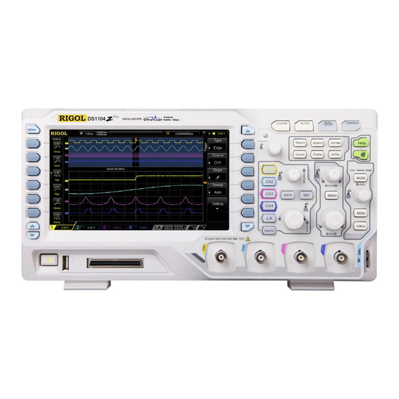
Summarization of Contents
Guaranty and Declaration
Copyright Information
Copyright information for the RIGOL DS1000Z Quick Guide.
Trademark Information
Details about RIGOL's registered trademark.
Publication Number
Identifier for the document's publication.
Important Notices
Statements regarding product usage, specifications, and liability.
Product Certification Standards
Product conformity to national, industrial, and ISO standards.
Contact RIGOL
Contact details for support, email, and website.
Safety Requirements
General Safety Summary
Essential safety guidelines for operating the instrument.
Safety Notices and Symbols
Explanation of warning/caution notices and safety symbols.
Product Safety Terms
Definitions of DANGER, WARNING, and CAUTION terms.
Product Safety Symbols
Icons representing electrical hazards and grounding.
Measurement Category and Ventilation
Measurement Category Definitions
Classification of measurement categories for electrical safety.
Ventilation Requirements
Guidelines for ensuring proper airflow for instrument cooling.
Working Environment
Environmental Conditions
Operating temperature, humidity, and altitude limits.
Installation (Overvoltage) Category
Specifies the overvoltage category the product is designed for.
Pollution Degree
Specifies the pollution degree the instrument is designed for.
Care and Cleaning
Instrument Care
Recommendations for instrument storage and handling.
Cleaning Procedures
Procedures for safely cleaning the instrument's exterior and display.
Environmental and Document Overview
Product End-of-Life Handling
Guidance on recycling and disposing of the product.
Document Conventions
Explains conventions for keys, menus, and operation steps.
Quick Start Guide
General Inspection Procedure
Initial checks for packaging, instrument, and accessories.
Preparation for Operation
Adjusting Supporting Legs
Instructions for using the adjustable legs for stable placement.
Connecting to AC Power Supply
Guide for connecting the instrument to the mains power.
Turn-on Checkout and Probe Connection
Turn-on Checkout Process
Steps to perform after powering on the oscilloscope.
Connecting Passive Probes
Instructions for connecting passive probes to the oscilloscope.
Connecting Logic Probes
Logic Probe Connection Steps
Detailed steps for connecting a logic probe.
Function Inspection
Using the Compensation Signal
Procedure for checking the probe's compensation signal.
Square Waveform Verification
Expected waveform display for function inspection.
Front Panel Layout
Front Panel Control Descriptions
Detailed list of front panel controls and their functions.
Rear Panel Overview
Handle and Connectivity Ports
Description of the carrying handle, LAN, and USB ports.
Trigger Output and Pass/Fail
Explanation of trigger output and pass/fail signal functions.
Source Output, Lock Hole, and Fuse
Details on signal source outputs, security lock, and fuse replacement.
AC Power Cord Connector
Connection point for the AC power cord.
Vertical Controls Overview
Vertical Controls (Position/Scale)
Adjusts vertical position and scale of waveforms.
MATH and REF Functions
Access to math operations and reference waveform comparison.
Digital and Horizontal Controls
Logic Analyzer Function
Controls the logic analyzer function.
Signal Source Settings
Settings for the instrument's signal source.
Trigger and Horizontal Controls
Horizontal Controls
Adjusts horizontal position and time base.
Trigger Controls
Settings for trigger modes and levels.
Front Panel Button Functions
CLEAR, AUTO, RUN/STOP, SINGLE
Functions of CLEAR, AUTO, RUN/STOP, and SINGLE buttons.
Multifunction Knob and Menus
Multifunction Knob Operation
Adjusts brightness and navigates menus.
Function Menus (Measure, Acquire, Storage, Cursor)
Access to measurement, acquisition, storage, and cursor settings.
Display, Utility, and Print Functions
Display Settings
Settings for screen display parameters.
Utility Settings
System settings and advanced functions access.
Print Function
Function to print screen or save to USB.
User Interface Overview
Auto Measurement Items
Options for automatic measurement of parameters.
Digital Channel Display
Display of digital channel information and waveforms.
User Interface Details
Status and Time Base
Current operational state and horizontal time base setting.
Sample Rate and Triggering
Displays sample rate, memory depth, trigger type, source, and level.
Waveform Memory and Position
Schematic of waveform memory and horizontal position adjustment.
Channel Controls and Status
Vertical Scale Settings
Sets vertical scale for channels 1-4.
Channel Labels and Status
Displays channel labels and digital channel status.
Message Box
Displays prompt messages to the user.
Source and Notification Area
Source Waveforms
Displays waveform types for Source 1 and Source 2.
Notification Icons
Displays sound and USB disk status icons.
Operation Menu Symbols
Explains symbols used in menu navigation.
Parameter Setting and Security
Parameter Setting Methods
Two methods for setting instrument parameters.
Security Lock Usage
Instructions for using a security lock to secure the instrument.
Built-in Help System
Help Interface Overview
Description of the help system interface and navigation.
Troubleshooting Common Issues
Display and Signal Problems
Solutions for no display and no waveform issues.
Waveform Stability Issues
Methods to resolve unstable waveform display.
RUN/STOP and Waveform Issues
Diagnosing problems with RUN/STOP and waveform display.
Troubleshooting Advanced Issues
Waveform Display and USB Issues
Solutions for ladder-like display and USB connection failures.
USB Storage Recognition
Steps to resolve issues with USB drive recognition.


Need help?
Do you have a question about the DS1054 and is the answer not in the manual?
Questions and answers