Table of Contents
Advertisement
Quick Links
Download this manual
See also:
User Manual
Advertisement
Table of Contents

Subscribe to Our Youtube Channel
Related Manuals for HPE StoreVirtual 3200


Summary of Contents for HPE StoreVirtual 3200
-
Page 1: Installation Guide
HPE StoreVirtual 3200 Storage System Installation Guide Abstract This guide describes how to install, configure, and troubleshoot the HPE StoreVirtual 3200 Storage product. Part Number: 839935-003 Published: November 2017 Edition: 3... - Page 2 © Copyright 2016, 2016 Hewlett Packard Enterprise Development LP Notices The information contained herein is subject to change without notice. The only warranties for Hewlett Packard Enterprise products and services are set forth in the express warranty statements accompanying such products and services. Nothing herein should be construed as constituting an additional warranty. Hewlett Packard Enterprise shall not be liable for technical or editorial errors or omissions contained herein.
-
Page 3: Table Of Contents
Product configurations........................5 Component identification......................5 Storage controller enclosure ..................... 5 Recovery/power button...................... 9 HPE StoreVirtual 3200 drive enclosure................9 Status LED descriptions......................10 Common status LEDs.......................11 Storage controller enclosure controller module status LEDs........... 12 Drive enclosure I/O module status LEDs................. 14 Prepare for installation................. - Page 4 Configuring the network for iSCSI systems..............45 Choosing to continue configuration now or later.............. 46 Setting Management Credentials..................46 Configuring Storage Settings ..................47 Creating a Default Volume....................47 Setting Remote Support....................47 Setting a Proxy.........................47 Completing Configuration Setup....................48 Troubleshooting..................49 Complete the Configuration Setup if interrupted.................49 Websites....................
-
Page 5: Product Overview
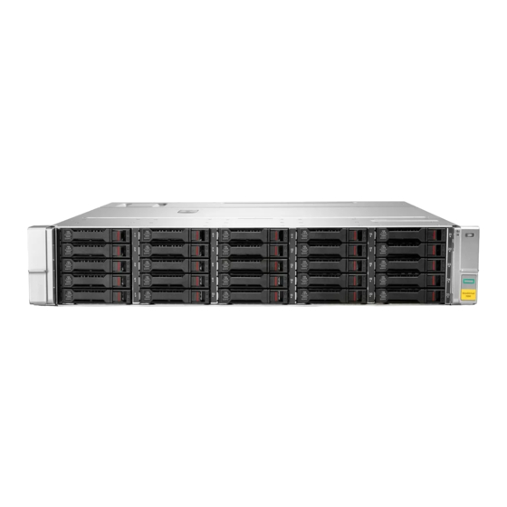
Product configurations The basic configuration of the HPE StoreVirtual 3200 Storage system is a 2U array enclosure with dual storage controllers containing either 12 LFF drive bays or 25 SFF drive bays. Scale up the system by adding drives. - Page 6 7. System status LED 3. Pullout tab with system serial number label 8. Power supply status LED 4. Fan module 9. Power supply module 5. Controller module Figure 4: HPE StoreVirtual 3200 Storage 1 GbE controller module (2 port) Product overview...
- Page 7 10. SAS data port to optional drive enclosure 5. Recovery/power button (See Recovery/power (DP-1) button). Figure 5: HPE StoreVirtual 3200 Storage 1 GbE controller module (4 port) 1. Controller locate UID 7. Service port (Micro-B USB) 2. Controller status LED 8.
- Page 8 4. USB type A port 10. Data port status LEDs 5. 10GBase-T ports 11. SAS data port to optional drive enclosure (DP-1) 6. Recovery/power button (See Recovery/power button). Figure 8: HPE StoreVirtual 3200 Storage 8Gb/16 Gb Fibre Channel controller module (2 port) Product overview...
-
Page 9: Recovery/Power Button
HPE StoreVirtual 3200 drive enclosure The HPE StoreVirtual 3200 drive enclosure is available in either an LFF configuration with 12 drive bays, or an SFF configuration with 25 drive bays. The components on the rear of the drive enclosure are identical for both the LFF and SFF configurations. -
Page 10: Status Led Descriptions
1. Disk drive locate UID 3. System status LED 2. Disk drive status LED 4. System locate UID/push button Figure 11: HPE StoreVirtual 3200 drive enclosure rear view 1. Pullout tab with serial number label 10. System status LED 2. I/O module (slot 1) 11. -
Page 11: Common Status Leds
For the location of the array enclosure LEDs, see Storage controller enclosure . • For the location of the drive enclosures LEDs, see HPE StoreVirtual 3200 drive enclosure. Common status LEDs The following LEDs are used on both the array enclosure and the drive enclosure. -
Page 12: Storage Controller Enclosure Controller Module Status Leds
Indicator Display Description Blue on Location requested. Safe to remove. Blue flashing Location requested. Do not remove. Table 4: Disk drive status LEDs Blue UID LED Bicolor (green/amber) power or Description status LEDs No power or an inactive spare Green on Powered on, no I/O, no fault Green flicker Powered on, active I/O, no fault... - Page 13 Table 5: Array controller module status LEDs Blue UID LED Green Amber status Description power LED No power Powered on, no fault Solid Fault Flash Predictive failure Manually initiated locate, no fault, safe to remove Flash Manually initiated locate, no fault, do not remove Automatically initiated locate, fault, safe to remove...
-
Page 14: Drive Enclosure I/O Module Status Leds
Fibre channel LED status Table 7: FC LED statuses Green LED Amber LED Description Fault or no power Link at high speed, no activity Flicker Link at high speed with activity No link or no cable connected Link at low speed, no activity Flicker Link at low speed with activity Flash... - Page 15 Indicator Display Description Green on, amber on Link at low speed with no activity Green flashing, amber on Link at low speed with activity Green off, amber on No link or no cable connected Green flashing, amber flashing Location requested I/O module status LED Green on, amber off Normal operation...
-
Page 16: Prepare For Installation
Prepare for installation Verifying the product contents The following items are included with the HPE StoreVirtual 3200 Storage product. Verify that all items are included before beginning the installation. • 2U rack rail kit for each enclosure • Array enclosure •... -
Page 17: Determining Who Will Install And Configure The Storage System
Storage management experience is required to successfully install and configure this product. If you are not familiar with installing and configuring storage array systems, HPE can install this product for you. For more information, see the Business & IT Services website: http://www.hpe.com/info/services. -
Page 18: Planning The Storage Configuration
Planning the storage configuration Proper planning of the system storage and its subsequent performance is critical to a successful deployment of the drive enclosure. Improper planning or implementation can result in wasted storage space, degraded performance, or inability to expand the system to meet growing storage needs. Storage planning considerations include: •... -
Page 19: Preparing The Site
LFF 7.2K drives: two pairs of six or 12 drives in RAID 6 Disk drive sizes and types The HPE StoreVirtual 3200 Storage system configuration should include disk drives of the same size and performance capability. When different drive types are installed in an enclosure, the usable capacity and the processing ability of the entire storage system is affected. - Page 20 For protection against a power-source failure, obtain and include two uninterruptible power supplies (UPS) in your installation. See the following URL for a list of available UPS: https:// www.hpe.com/us/en/product-catalog/servers/uninterruptible-power-system.html. For power consumption specifications, see the HPE StoreVirtual 3200 Storage QuickSpecs. Prepare for installation...
-
Page 21: Install The Hardware
Install the hardware Install the following hardware components: • Rail kit • Enclosure • Disk drives • Cables Installing the rail kits Procedure 1. Identify the rack locations for the enclosures. 2. Loosen the back bracket on the standard rail kit to accommodate the enclosure. Attach the rear hold down brackets by sliding the tab with the arrow pointed forward (1) into the corresponding slot on the left and right side of the rear of the chassis. - Page 22 4. Use guide pins to align the shelf mount kit to theEIA column holes. 5. To engage the rail to the rear of the rack, push the rail toward the back of the rack until the spring hook snaps into place. 6.
-
Page 23: Installing The Enclosure
8. Secure the front of the rail to the front EIA column using the flat securing screw/guide pin (provided in the package) in the bottom screw position of the rail. Installing the enclosure CAUTION: Install disk drives in the enclosure only after mounting the enclosure in the rack. An enclosure with disk drives installed is too heavy to lift safely. - Page 24 • The array enclosure installed on the top. • SFF drive enclosures installed below the array enclosure. • LFF drive enclosures installed below the SFF drive enclosures. If you put the array enclosure on top, the numbering will start at the top, which can be more intuitive and helpful.
-
Page 25: Installing Disk Drives
Installing disk drives Depending on the types of disk drives being used, the following number of drives can be installed in a single enclosure: • LFF: 12 drives • SFF: 25 drives CAUTION: To prevent improper cooling and thermal damage, operate the enclosure only when all bays are populated with either a component or a drive blank. -
Page 26: Installing A Disk Drive
Installing a disk drive CAUTION: To prevent improper cooling and thermal damage, operate the enclosure only when either a disk drive or a drive blank is installed in every bay. Procedure 1. Remove the drive blank. Removing an SFF drive blank is similar to the example shown for the LFF drive blank. -
Page 27: Connecting The System Cables
5. In the StoreVirtual Management Console, select Configure RAID to add the new storage. See the HPE StoreVirtual Online Help or the HPE StoreVirtual Management Console User Guide for more information. Connecting the system cables... -
Page 28: Cabling Best Practices
Procedure 1. Connect the StoreVirtual 3000 drive enclosures to the array enclosure (if included). 2. Connect the array enclosure to the network and hosts. 3. Connect the power cords to the system components. Cabling best practices • Use the shortest possible cable between devices. Shorter cables reduce the possibility of signal degradation that might occur over longer distances. - Page 29 For iSCSI configurations, the host must have two Ethernet ports capable of accessing the StoreVirtual 3200 bonded interface to facilitate the transfer of iSCSI data between the host and the array. For Fibre Channel configurations, the host must have two Fibre Channel ports zoned to have access to the StoreVirtual 3200 storage controllers.
- Page 30 two or four interfaces. The system supports two 10GbE/10GBase-T interfaces in a bond and two 1GbE interfaces in a bond. No additional network switch configuration is required. • Link aggregation (802.3ad) – Link aggregation bonds provide a single logical interface with the sum of the bandwidth of the physical network interfaces.
- Page 31 Controller with a 10GbE card 1. Option card 10GbE ports 2. Built-in 1G ports On a 10GbE system, only the 10GbE interfaces are bonded in the Configuration setup. The 1GbE ports can be put in a separate bond later. The 10GbE and 1GbE interfaces must be on different subnets but can be used simultaneously by assigning different traffic types to the bonds.
- Page 32 Controller with a Fibre Channel card 1. Option card Fibre Channel ports 2. Built-in 1G ports The built-in 1G ports are bonded and share a subnet mask. Fibre Channel ports do not require IP addresses, so no bonding is necessary. Network configuration for array enclosure with 1 GbE controller modules (two port) All iSCSI, Remote Copy, and Management traffic are routed through these two ports.
- Page 33 Servers 1 GbE iSCSI SAN SV3200 Figure 18: Configuration using four 1 GbE ports and one switch Network configuration for array enclosure with 1 GbE controller modules (four ports) All iSCSI, Remote Copy, and Management traffic are routed through these four ports. The 1 GbE ports are bonded together for redundancy and performance during the Configuration Setup procedure.
- Page 34 1. Servers 2. 1 GbE iSCSI SAN 3. Network cloud connections 4. StoreVirtual storage system Network configuration for array enclosure with 10 GbE/10GBase-T controller modules (two ports) All iSCSI, Remote Copy, and Management traffic is routed through these ports. The ports are bonded together for redundancy and performance during the Configuration Setup procedure.
- Page 35 Figure 20: Configuration using four 10 GbE / 10GBase-T ports and two switches 1. Servers 2. 10 GbE/ 10GBase-T iSCSI SAN 3. Network cloud connections 4. StoreVirtual storage system Network configuration for array enclosure with Fibre Channel controller modules (two ports) The two Fibre Channel ports on each controller are used for data connections.
- Page 36 5. 1 GbE iSCSI SAN Connecting the StoreVirtual 3200 drive enclosure Up to three HPE StoreVirtual 3200 drive enclosures can be connected to the array enclosure. The drive enclosures must be connected to the array enclosure using an asymmetric cabling scheme as shown in the following figures.
- Page 37 1. Connect DP-1 on the storage controller in slot 1 to DP-1 on the I/O module in slot 1 of the drive enclosure. 2. Connect DP-1 on the storage controller in slot 2 to DP-1 on the I/O module in slot 2 of the drive enclosure.
-
Page 38: Multipathing With Iscsi Configurations
Connecting to three drive enclosures Figure 24: Three drive enclosure cabling configuration 1. Array enclosure 3. Drive enclosure 2 2. Drive enclosure 1 4. Drive enclosure 3 1. Connect DP-1 on the storage controller in slot 1 to DP-1 on the I/O module in slot 1 of the first drive enclosure. -
Page 39: Connecting The System Power Cords
IP addresses per storage controller for increased performance. • Round Robin is the suggested load balancing policy for the StoreVirtual 3200 iSCSI network configuration. Windows Server 2016 defaults to Round Robin with Subset. VMware ESXi 6.0 uses the Round Robin Path Selection Policy by default. - Page 40 Connection Method Level of Protection Connected to: Protects from downtime when one of the enclosure power supplies fails. Protects from data loss when one of the power sources fails, due to a pulled One power source cable or tripped breaker. The remaining power supply/fan module can operate the enclosure until you install a replacement module.
-
Page 41: Powering On And Configuring The Storage System
Powering on and configuring the storage system After all enclosures are installed and properly connected, use the MGMT port to perform the following configuration steps. • Setting the initial network configuration on page 41 • Powering on the storage system on page 41 •... -
Page 42: Using The Configuration Setup For Initial Storage System Settings
Enter the IP address exactly as noted. Do not use DNS. 3. Enter admin as the user name and password to log on. 4. On the Welcome window of the HPE StoreVirtual 3200 Management Console, click Configuration Setup. Using the Configuration Setup for initial storage system settings... -
Page 43: Accepting The License Agreement
Setting a Proxy Accepting the license agreement Procedure 1. Select I accept the HPE End User License Agreement to continue the initial configuration. 2. If you want to view the license, click HPE End User License Agreement. Reviewing the initial health scan The system conducts the initial health scan to make sure that the system is healthy and can be configured. -
Page 44: Configuring Disk Raid
OK. Data network configuration The network ports that are displayed have been discovered on the system. HPE recommends bonding the network ports. The data and management traffic take place on the bonded interfaces. You can configure either a Fibre Channel system or an iSCSI system. -
Page 45: Configuring The Network For Fibre Channel Systems
Configuring the network for Fibre Channel systems Prerequisites The IP addresses for the two storage controllers should be on the same network. Procedure 1. Select the type of bond to be used: • The default, Adaptive Load Balancing (ALB), is the recommended type in most cases. •... -
Page 46: Choosing To Continue Configuration Now Or Later
• Bond IP addresses—Enter the two static IP addresses that you designated for the iSCSI bond. • Subnet Mask—Enter the subnet mask. Choosing to continue configuration now or later Do you want to configure provisioning, remote support, or proxy settings? •... -
Page 47: Configuring Storage Settings
• Select Yes to create a default volume. Setting Remote Support Remote support allows the system to report its status and system information to HPE. This information could be used as a baseline for future support cases if necessary. Procedure 1. -
Page 48: Completing Configuration Setup
Correct the errors and click OK. 3. When prompted, confirm your choice regarding whether HPE Support may contact you. The progress of each individual configuration task is displayed. You can view further information for each task by clicking Task Details. -
Page 49: Troubleshooting
Troubleshooting Complete the Configuration Setup if interrupted Symptom If the Configuration Setup is interrupted before it finishes, you must return to the Configuration Setup to complete the configuration. Cause You might navigate away from the Configuration Setup page, or get interrupted by another demand. Also, clicking the StoreVirtual menu interrupts the process. -
Page 50: Websites
Single Point of Connectivity Knowledge (SPOCK) Storage compatibility matrix www.hpe.com/storage/spock Storage white papers and analyst reports www.hpe.com/storage/whitepapers For additional websites, see Support and other resources. StoreVirtual 3200 websites StoreVirtual 3200 documentation (Storage Information Library) http://www.hpe.com/info/sv3200-docs StoreVirtual 3200 documentation (HPESC) http://www.hpe.com/info/StoreVirtual3200Manuals Websites... -
Page 51: Support And Other Resources
Support and other resources Accessing Hewlett Packard Enterprise Support • For live assistance, go to the Contact Hewlett Packard Enterprise Worldwide website: http://www.hpe.com/assistance • To access documentation and support services, go to the Hewlett Packard Enterprise Support Center website: http://www.hpe.com/support/hpesc Information to collect •... -
Page 52: Customer Self Repair
IMPORTANT: Access to some updates might require product entitlement when accessed through the Hewlett Packard Enterprise Support Center. You must have an HPE Passport set up with relevant entitlements. Customer self repair Hewlett Packard Enterprise customer self repair (CSR) programs allow you to repair your product. If a CSR part needs to be replaced, it will be shipped directly to you so that you can install it at your convenience. -
Page 53: Warranty And Regulatory Information
Warranty and regulatory information For important safety, environmental, and regulatory information, see Safety and Compliance Information for Server, Storage, Power, Networking, and Rack Products, available at www.hpe.com/support/Safety- Compliance-EnterpriseProducts. Warranty information HPE ProLiant and x86 Servers and Options www.hpe.com/support/ProLiantServers-Warranties HPE Enterprise Servers www.hpe.com/support/EnterpriseServers-Warranties... -
Page 54: Turkey Rohs Material Content Declaration
Local representative information Kazakh: • Russia • Belarus: • Kazakhstan: Manufacturing date: The manufacturing date is defined by the serial number. CCSYWWZZZZ (serial number format for this product) Valid date formats include: • YWW, where Y indicates the year counting from within each new decade, with 2000 as the starting point;...
Need help?
Do you have a question about the StoreVirtual 3200 and is the answer not in the manual?
Questions and answers