Table of Contents
Advertisement
Quick Links
Manual
ADVANTECH
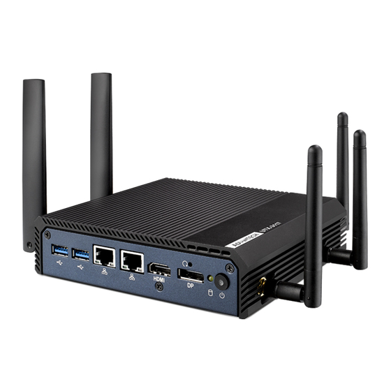
UTX-3117
Embedded BOX PC with Intel® Apollo Lake Prozessor
The information contained in this document has been carefully researched and is, to the best of our
knowledge, accurate. However, we assume no liability for any product failures or damages, immediate or
consequential, resulting from the use of the information provided herein. Our products are not intended for
use in systems in which failures of product could result in personal injury. All trademarks mentioned herein
are property of their respective owners. All specifications are subject to change without notice.
Advertisement
Table of Contents

Subscribe to Our Youtube Channel
Related Manuals for Advantech UTX-3117


Summary of Contents for Advantech UTX-3117
- Page 1 Manual ADVANTECH UTX-3117 Embedded BOX PC with Intel® Apollo Lake Prozessor The information contained in this document has been carefully researched and is, to the best of our knowledge, accurate. However, we assume no liability for any product failures or damages, immediate or consequential, resulting from the use of the information provided herein.
- Page 2 User Manual UTX-3117...
- Page 3 No part of this manual may be reproduced, copied, translated or transmitted in any form or by any means without the prior written permission of Advantech Co., Ltd. Information provided in this manual is intended to be accurate and reliable. How- ever, Advantech Co., Ltd.
-
Page 4: Declaration Of Conformity
This device complies with Part 15 of the FCC Rules. Operation is subject to the fol- lowing two conditions: (1) This device may not cause harmful interference, and (2) this device must accept any interference received, including interference that may cause undesired operation. UTX-3117 User Manual... -
Page 5: Safety Instructions
Technical Support and Assistance Visit the Advantech website at http://support.advantech.com where you can find the latest information about the product. Contact your distributor, sales representative, or Advantech's customer service center for technical support if you need additional assistance. Please have the following information ready before you call: –... -
Page 6: Industry Canada Statement
(s). Son utilisation est soumise à Les deux conditions suivantes: (1) cet appareil ne peut pas provoquer d’interférences et (2) cet appareil doit accepter Toute interférence, y compris les interférences qui peuvent causer un mau- vais fonctionnement du dispositif. UTX-3117 User Manual... - Page 7 équipement." European Union Declaration of Conformity Statement We, Advantech, declare under our sole responsibility that the product, model, is in conformity with all applicable essential requirements Necessary for CE marking, fol- lowing the provisions of the European Council Directives 2004/108/EC (EMC Direc-...
- Page 8 This symbol on the product indicates compliance with Directive 2002/96/EC (WEEE). Do not dispose of product in unsorted municiple waste. Please recycle this product in a responsible manner. Refer to local environmental regulations for proper recycling; do not dispose of product in unsorted municipal waste. UTX-3117 User Manual...
-
Page 9: Packing List
Packing List Before installation, please ensure the following items have been shipped: 1 x UTX-3117 unit 1 x DC 12 V 36W power adaptor 1 x China RoHS 1 x Warranty card 1 x Chinese user manual... - Page 10 (For power adapter 1757004096-01) Power Cable 3-pin 180cm, Europe type 170203183C (For power adapter 1757004096-01) Power Cable 3-pin 180cm, UK type 170203180A (For power adapter 1757004096-01) Power Cable 3-pin 183cm, PSE Mark type 1700008921 (For power adapter 1757004096-01) Optional Items UTX-3117 User Manual...
- Page 11 UTX-3117 User Manual...
-
Page 12: Table Of Contents
2.2.21 High Definition Multimedia Interface(HDMI1)......21 2.2.22 DisplayPort (DP1)...............21 2.2.23 DDR3L SO-DIMM Socket (DIMMB1)..........22 2.2.24 SATA LED(D10)................22 2.2.25 Power Button(PWRBTN1) ............22 Chapter Peripheral Installation .......23 HDD Installation..................24 Mini PCIe Module Installation..............26 Chapter BIOS Setup .........29 Introduction .....................30 Entering Setup ..................31 UTX-3117 User Manual... - Page 13 4.2.1 Main Menu.................. 3 1 4.2.2 Advanced BIOS Features............32 4.2.3 Chipset..................5 2 4.2.4 Security Boot ................59 4.2.5 Boot .................... 61 4.2.6 Save & Exit................. 6 2 UTX-3117 User Manual...
-
Page 14: Chapter 1 Introduction
Chapter Introduction This Chapter briefly introduces the UTX-3117 product. -
Page 15: Overview
& play gateway which is ideal for smart city street lighting, smart metering, smart parking, smart agriculture, HVAC, healthcare, industrial automation and more. UTX-3117 is compatible with Microsoft Windows 10 IoT Enterprise, Yocto Linux, and Wind River Pulsar OS. Furthermore, UTX-3117 has Advantech intelligent software WISE-PaaS integrated and is certificated with AWS Greengrass IoT solution to offer a total solution for bridging connectivity from edge sensors to the cloud. -
Page 16: System Configuration
System Configuration The following diagram is a block drawing of the UTX-3117. HDMI DDR3L Non-ECC 1333/1600/1867 MHz, up to 8G DP1.2 GbE 1: PCIE x1 1 SATA 3.0 I211AT 600MBs GbE 2: PCIE x1 RTL8111G Intel 2 USB3.0 USB3.0 F/S mini PCIE, Apollo Lake USB2.0... -
Page 17: General Specifications
Mechanical Specifications 1.4.1 Mechanical Specifications (Terminal) System Dimensions: 152 X 128 X 37.1 mm (5.98" X 5.2" X 1.46") Carton Dimensions: 255 (L) X 235 (W) X 160 (H) mm Gross Weight: 2.0 kg Net Weight: 1.8 kg UTX-3117 User Manual... -
Page 18: Environmental Specifications
Storage Temperature: -40 ~ 60° C Relative Humidity: 40 ~ 95% RH (Non-condensed) Safety CE / UL/CB/CCC/BSMI FCC class B approved for USA, Canada, and EU Vibration: With SSD: 3Grms, 60068-2-64, random, 5 ~ 500 Hz, 1 hr/axis UTX-3117 User Manual... - Page 19 UTX-3117 User Manual...
-
Page 20: Chapter 2 Jumper And Connector List
Chapter Jumper and Connector List... -
Page 21: Connectors & Jumpers
Connectors & Jumpers Figure 2.1 Top View UTX-3117 User Manual... -
Page 22: Figure 2.2 Bottom View
(14) Next Generation Form Factor (M.2_1) (15) SATA Signal Connector (SATA1) (16) USB 3.0 Connector(USB1) (17) SATA Power Connector (SATA_PWR1) (18) USB 3.0 Connector(USB2) (19) RJ45 Connector(LAN2) (20) RJ45 Connector(LAN1) (21) High Definition Multimedia Interface(HDMI1) (22) DisplayPort(DP1) (23) DDR3LSO-DIMM Socket (DIMMB1) UTX-3117 User Manual... -
Page 23: Connectors
Table 2.1: RS485/RS422selection pin header (J485/422) Function Setting RS485 (Default) 1 and 2 RS232 2 and 3 Table 2.2: AT/ATX Mode Selection (PSON1) Function Setting AT Mode 1 and 2 ATX Mode (Default) 2 and 3 Connectors 2.2.1 CPU-System on chip(SOC1) UTX-3117 User Manual... -
Page 24: Bios Flash(Spi1)
2.2.2 BIOS Flash(SPI1) Signal Signal SPI_Z_CS0 SPI_Z_CLK SPI_Z_MISO SPI_Z_IO3 SPI_Z_IO2 +V1.8SB_SPI SPI_Z_MOSI 2.2.3 DDR3L SO-DIMM Socket (DIMMA1) 2.2.4 DC input Connector(DCIN1) Signal Power input UTX-3117 User Manual... -
Page 25: Minipcie Connector (Mini-Pcie1)
Reserved +1.5V Reserved SIM_VCC1 SIM_IO1 Reserved SIM_CLK1 Reserved SIM_RST1 SIM_SPU1 Reserved Reserved DISABLE# RESET# Reserved +3.3Vaux Reserved +1.5V Reserved Reserved Reserved MINI-PCIE1 _RESET# USB_D- USB_D+ +3.3Vaux +3.3Vaux Reserved Reserved Reserved Reserved Reserved Reserved +1.5V Reserved Reserved +3.3Vaux UTX-3117 User Manual... -
Page 26: Sim Card Socket (Sim1)
2.2.6 SIM Card Socket (SIM1) Signal Signal SIM_VCC1 SIM_RST1 SIM_CLK1 SIM_SPU1 2.2.7 Low Pin Count Header (LPC1) Signal Signal SOC_LPC_AD1 CLKOUT_25M_LPC SOC_LPC_AD0 PM_PLTRST# +V3.3 SOC_LPC_FRAME# SOC_LPC_AD3 SOC_LPC_AD2 UTX-3117 User Manual... -
Page 27: Minipcie And Msata Connector (Mini-Pcie2)
Reserved DISABLE# DETECT# RESET# PCIE_RX+ +3.3Vaux PCIE_RX- +1.5V SMB_CLK PCIE_TX- SMB_DATA PCIE_TX+ USB_D- USB_D+ +3.3Vaux +3.3Vaux Reserved V1.2_DETECT# LED_WLAN# Reserved Reserved Reserved +1.5V Reserved MSATA_DETECT# +3.3Vaux mSATA: Signal Signal Reserved +3.3V Reserved Reserved +1.5V Reserved Reserved Reserved UTX-3117 User Manual... -
Page 28: Spi Programming Pin Header (Spi_Cn1)
Reserved Reserved Reserved Reserved Reserved Reserved DETECT# Reserved +3.3V +1.5V SMB_CLK SMB_DATA Reserved Reserved +3.3V +3.3V Reserved Reserved Reserved Reserved Reserved Reserved +1.5V Reserved MSATA_DETECT# +3.3V 2.2.9 SPI Programming Pin Header (SPI_CN1) Signal Signal +3.3V MISO MOSI UTX-3117 User Manual... -
Page 29: Com Port (Com1)
2.2.10 COM Port (COM1) Signal Signal DCD# DSR# RTS# CTS# DTR# 2.2.11 General Purpose I/O Pin Header (GPIO1) Signal Signal GPIO0 GPIO4 GPIO1 GPIO5 GPIO2 GPIO6 GPIO3 GPIO7 +3.3V UTX-3117 User Manual... -
Page 30: Hd Analog Audio Interface (Audio1)
2.2.12 HD Analog Audio Interface (AUDIO1) Signal Signal CONN_FRONT_L GND_A CONN_FRONT_R GND_A GND_A GND_A CONN_MIC1_L FRONT_SENSE_A 2.2.13 COM Port (COM2) Signal COM2_422_485_TX- COM2_422_485_TX+ COM2_422_RX- COM2_422_RX+ UTX-3117 User Manual... -
Page 31: Next Generation Form Factor (M.2_1)
Signal Signal PCIE_RX3- +V3.3SB_M.2 USB_D4+ +V3.3SB_M.2 USB_D4- CK100M_NGFF+ CK100M_NGFF- NGFF_I2S3_Z_BCLK NGFF_PMU_SUSCLK SDIO_WIFI_CLK NGFF_I2S3_Z_SYNC NGFF_PLTRST# SDIO_WIFI_CMD PCIE_REQ2_NGFF# NGFF_I2S3_Z_SDI NGFF_BT_DISABLE# SDIO_WIFI_D0 PCIE_NGFF_WAKE2# NGFF_I2S3_Z_SDO NGFF_WIFI_DISABLE# SDIO_WIFI_D1 SDIO_WIFI_D2 SDIO_WIFI_D3 NGFF_CONN_UART_WAKE# SDIO_WIFI_WAKE# NGFF_UART0_Z_RXD SDIO_WIFI_RST NGFF_UART0_Z_TXD NGFF_UART0_Z_CTS# NGFF_PCIE_TX3+ NGFF_UART0_Z_RTS# NGFF_PCIE_TX3- +V3.3SB_M.2 +V3.3SB_M.2 PCIE_RX3+ UTX-3117 User Manual... -
Page 32: Sata Signal Connector (Sata1)
2.2.15 SATA Signal Connector (SATA1) Signal Signal SATA0_Z_RX+ SATA0_Z_TX+ SATA0_Z_TX- SATA0_Z_RX- SATA0_Z_RX+ 2.2.16 USB 3.0 Connector(USB1) 2.2.17 USB 3.0 Connector(USB2) Signal Signal +USBV1 USB_D0- USB3X0_Z_TX- USB_D0+ USB3X0_Z_TX+ GND_F1 USB3X0_Z_RX- GND_F1 USB3X0_Z_RX+ UTX-3117 User Manual... -
Page 33: Sata Power Connector (Sata_Pwr1)
2.2.18 SATA Power Connector (SATA_PWR1) Signal Signal 2.2.19 RJ45 Connector(LAN1) 2.2.20 RJ45 Connector(LAN1) RJ45 Signal Signal LAN2_TCT LAN2_MDI3- LAN2_MDI0+ LAN1_TCT LAN2_MDI0- GND_LAN LAN2_MDI1+ GND_F1 LAN2_MDI1- LAN2_LED1_Z_ACT# LAN2_TCTG +V3.3_LAN2 LAN2_MDI2+ LAN2_LED2_Z_1G# LAN2_MDI2- LAN2_LED0_Z_100M# UTX-3117 User Manual... -
Page 34: High Definition Multimedia Interface(Hdmi1)
2.2.21 High Definition Multimedia Interface(HDMI1) Signal Signal HDMI1_Z_D2+ HDMI1_Z_CLK- HDMI1_Z_D2- HDMI1_Z_D1+ HDMI1_SCL HDMI1_Z_D1- HDMI1_SDA HDMI1_Z_D0+ +V5_HDMI HDMI1_Z_D0- HDMI1_HPD HDMI1_Z_CLK+ 2.2.22 DisplayPort (DP1) Signal Signal DP1_0+ DP1_3- DP1_0- DP1_AUX_EN# DP1_1+ DP1_AUX+ DP1_1- DP1_2+ DP1_AUX- DP1_DP_HPD DP1_2- DP1_3+ +V3.3_DP1 UTX-3117 User Manual... -
Page 35: Ddr3L So-Dimm Socket (Dimmb1)
2.2.23 DDR3L SO-DIMM Socket (DIMMB1) 2.2.24 SATA LED(D10) 2.2.25 Power Button(PWRBTN1) UTX-3117 User Manual... -
Page 36: Chapter 3 Peripheral Installation
Chapter Peripheral Installation... -
Page 37: Hdd Installation
HDD Installation Unscrew the bottom cover screws. Secure 2.5" SATA HDD onto the bottom cover. The screws are in the accessory box. UTX-3117 User Manual... - Page 38 Connect SATA signal and power cable to the 2.5" SATA HDD. Secure the bottom cover in its original position. UTX-3117 User Manual...
-
Page 39: Mini Pcie Module Installation
Mini PCIe Module Installation Unscrew the bottom cover screws. Insert Mini PCIe module into the slot and secure the screw to fix the module. UTX-3117 User Manual... - Page 40 Connect the antenna cable to module. Secure the bottom cover in its original position. UTX-3117 User Manual...
- Page 41 UTX-3117 User Manual...
-
Page 42: Chapter 4 Bios Setup
Chapter BIOS Setup... -
Page 43: Introduction
AMI BIOS has been integrated into many, many motherboards for decades. With the AMI BIOS Setup program, users can modify BIOS settings and control various sys- tem features. This chapter describes the basic navigation of the UTX-3117 BIOS setup screens. -
Page 44: Entering Setup
System Date using the <Arrow> keys. Enter new values through the keyboard. Press the <Tab> key or the <Arrow> keys to move between fields. The date must be entered in MM/DD/YY format. The time must be entered in HH:MM:SS format. UTX-3117 User Manual... -
Page 45: Advanced Bios Features
4.2.2 Advanced BIOS Features Select the Advanced tab from the UTX-3117 setup screen to enter the Advanced BIOS Setup screen. You can select any of the items in the left frame of the screen, such as CPU Configuration, to go to the sub menu for that item. You can display an Advanced BIOS Setup option by highlighting it using the <Arrow>... - Page 46 4.2.2.1 Realtek PCIe GBE Family Controller Status Check the status of Realtek LAN port. 4.2.2.2 Check Intel® I201 Gigabit Network connection Status UTX-3117 User Manual...
- Page 47 4.2.2.3 Trusted Computing UTX-3117 User Manual...
- Page 48 Security Device Support Enable or disable BIOS support for security device. 4.2.2.4 APCI Settings UTX-3117 User Manual...
- Page 49 Enable Hibernation This item allows users to enable or disable hibernation. ACPI Sleep State This item allows users to set the ACPI sleep state. Lock Legacy Resource This item allows users to lock legacy device resources. UTX-3117 User Manual...
- Page 50 4.2.2.5 NCT5523D Super IO Configuration UTX-3117 User Manual...
- Page 51 Serial Port 1&2 Configuration This item allows users to enable or disable serial Ports 1/2 Change Settings This item allows users to change the serial port 1/2 4.2.2.6 Hardware Monitor UTX-3117 User Manual...
- Page 52 This item allows you to monitor HW status Execute Disable Bit This item allows users to enable or disable the No-Execution page protection. Intel Virtualization Technology When enabled, a VMM can utilize the additional hardware capabilities provided by Vanderpool Technology. UTX-3117 User Manual...
- Page 53 Digital I/O Configuration This item will allow users to set up Digital I/O 1~8 to "input" or "output". UTX-3117 User Manual...
- Page 54 Wake System From S5 Enable or disable system wake on alarm event. UTX-3117 User Manual...
- Page 55 Console Redirection This item allows users to enable or disable console redirection. 4.2.2.7 CPU Configuration This page shows CPU Information. Active Power Cores UTX-3117 User Manual...
- Page 56 When a processor thermal sensor trips (either core), the PROCHOT# will be driven. If bi-direction is enabled, external agents can drive PROCHOT# to throt- tle the processor. Thermal Monitor Enable or disable Thermal Monitor Monitor Mwait Enable/disable Monitor Mwait. P-STATE Coordination Change P-STATE Coordination type. UTX-3117 User Manual...
- Page 57 EIST Enabled or disabled Intel Speed Step function. Turbo Mode Enabled or disabled Turbo Mode Boot performance mode Select the performance state that the BIOS will set before OS handoff. UTX-3117 User Manual...
- Page 58 Power Limit 1 in Watts. Auto will program Power Limit 1 based on silicon default support value. Power Limit 1 Time Window Power Limit 1 Time Window Value in seconds. Auto will program Power Limit 1 Time Window based on silicon default support value. UTX-3117 User Manual...
- Page 59 Network Stack Enable or disable UEFI Network Stack. UTX-3117 User Manual...
- Page 60 CSM Support Enable or disable CSM Support.. 4.2.2.8 NVMe Configuration UTX-3117 User Manual...
- Page 61 4.2.2.9 USB Configuration UTX-3117 User Manual...
- Page 62 Hub descriptor. Mass storage device Mass storage device emulation type. 'AUTO' enumerates devices according to their media format. Optical drives are emulated as 'CDROM', drives with no media will be emulated according to a drive type. UTX-3117 User Manual...
- Page 63 4.2.2.10 Platform Trust Technology fTPM Enabled or disabled fTPM. UTX-3117 User Manual...
- Page 64 4.2.2.11 Security Configuration TXE HMRFPO This item allows users to enable or disable TXE HMRFPO. TXE EOP Message Send EOP Message before Enter OS. UTX-3117 User Manual...
-
Page 65: Chipset
4.2.3 Chipset 4.2.3.1 North Bridge UTX-3117 User Manual... - Page 66 UTX-3117 User Manual...
- Page 67 OS Selection Select the target OS. 4.2.3.2 Uncore Configuration UTX-3117 User Manual...
- Page 68 UTX-3117 User Manual...
- Page 69 This item allows users to enable or disable the Serial-ATA Port 2 device Spin Up Device This item allows users to enable or disable the Spin Up Device. SATA Device Type Identify the SATA port is connected to Solid State Drive or Hard Disk Drive. UTX-3117 User Manual...
- Page 70 UTX-3117 User Manual...
- Page 71 UTX-3117 User Manual...
-
Page 72: Security Boot
4.2.4 Security Boot UTX-3117 User Manual... - Page 73 4.2.4.1 Security Boot Attempt Secure Boot Secure Boot activated when platform key(PK) is enrolled, system mode is user/ deployed, and CSM function is disabled. Secure Boot Mode UTX-3117 User Manual...
-
Page 74: Boot
DARD mode or CUSTOM mode, this change is effect after save. And after eset, the mode will return to STANDARD mode. 4.2.5 Boot Bootup NumLock State Select the keyboard NumLock state. Quiet Boot Enables or disables Quiet Boot option. UTX-3117 User Manual... -
Page 75: Save & Exit
4.2.6 Save & Exit UTX-3117 User Manual... - Page 76 UTX-3117 User Manual...
- Page 77 No part of this publication may be reproduced in any form or by any means, electronic, photocopying, recording or otherwise, without prior written permis- sion of the publisher. All brand and product names are trademarks or registered trademarks of their respective companies. © Advantech Co., Ltd. 2018...
- Page 78 Our company network supports you worldwide with offices in Germany, Austria, Switzerland, Great Britain and the USA. For more information please contact: Headquarters Germany FORTEC Elektronik AG Lechwiesenstr. 9 86899 Landsberg am Lech Phone: +49 8191 91172-0 E-Mail: sales@fortecag.de Internet: www.fortecag.de Fortec Group Members FORTEC Elektronik AG...
Need help?
Do you have a question about the UTX-3117 and is the answer not in the manual?
Questions and answers