
Related Manuals for Advantech UNO-420-E0A


Summary of Contents for Advantech UNO-420-E0A
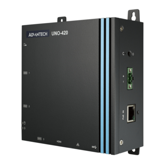
- Page 1 User Manual UNO-420 Intel® Atom™ PoE Powered Device Sensing Gateway with 3 x COM, 2 x LAN(1 x PoE), 8 x GPIO, HDMI, USB3.0...
- Page 2 No part of this manual may be reproduced, copied, translated or transmitted in any form or by any means without the prior written permission of Advantech Co., Ltd. Information provided in this manual is intended to be accurate and reliable. How- ever, Advantech Co., Ltd.
- Page 3 Because of Advantech’s high quality-control standards and rigorous testing, most of our customers never need to use our repair service. If an Advantech product is defec- tive, it will be repaired or replaced at no charge during the warranty period. For out- of-warranty repairs, you will be billed according to the cost of replacement materials, service time and freight.
- Page 4 這是甲類測試產品,在居住的環境中使用時,可能會造成射頻干擾,在這種情況下, 使用者會被要求採取某些適當的對策。 Technical Support and Assistance Visit the Advantech web site at www.advantech.com/support where you can find the latest information about the product. Contact your distributor, sales representative, or Advantech's customer service center for technical support if you need additional assistance. Please have the following information ready before you call: –...
- Page 5 The sound pressure level at the operator's position according to IEC 704-1:1982 is no more than 70 dB (A). DISCLAIMER: This set of instructions is given according to IEC 704-1. Advantech disclaims all responsibility for the accuracy of any statements contained herein.
- Page 6 安全指示 1. 請仔細閱讀此安全操作說明。 2. 請妥善保存此用戶手冊供日後參考。 3. 用濕抹布清洗設備前,請確認拔除電源線。請勿使用液體或去污噴霧劑清洗設備。 4. 對於使用電源線的設備,設備周圍必須有容易接觸到的電源插座。 5. 請勿在潮濕環境中試用設備。 6. 請在安裝前確保設備放置在可靠的平面上,意外摔落可能會導致設備損壞。 7. 設備機殼的開孔適用於空氣對,從而防止設備過熱。請勿覆蓋開孔。 8. 當您連接設備到電源插座前,請確認電源插座的電壓符合要求。 9. 請將電源線佈置在人們不易絆倒的位置,請勿在電源線上覆蓋任何雜物。 10. 請注意設備上所有的警告標示。 11. 如果長時間不使用設備,請拔除與電源插座的連結,避免設備被超標的電壓波動 損壞。 12. 請勿讓任何液體流入通風口,以免引起火灾或短路。 13. 請勿自行打開設備。為了確保您的安全,請透過經認證的工程師來打開設備。 14. 如遇下列情况,請由專業人員維修: 電源線或插頭損壞; 設備內部有液體流入; 設備曾暴露在過度潮濕環境中使用; 設備無法正常工作,或您無法透過用戶手冊來正常工作; 設備摔落或損壞; ...
- Page 7 設備名稱 : 路由器 型號 ( 型式 ):UNO-420 Equipment name Type designation (Type) 限用物質及其化學符號 Restricted substances and its chemical symbols 鉛 汞 鎘 六價鉻 多溴聯苯 多溴二苯醚 單元 Unit Lead Mercury Cadmium Hexavalent Polybrominated Polybrominated- (Pb) (Hg) (Cd) chromium biphenyls diphenyl ethers (Cr+6) (PBB) (PBDE)
- Page 8 UNO-420 User Manual viii...
-
Page 9: Table Of Contents
Contents Chapter Overview..........1 Introduction ....................2 Safety Precautions ..................2 Accessories....................3 Chapter Hardware Functionality.......5 Introduction ....................6 Figure 2.1 Left side view of UNO-420.......... 6 Figure 2.2 Bottom view of UNO-420..........6 Figure 2.3 Right side view of UNO-420 ........6 UNO-420 Interface .................. - Page 10 Table A.5: GPIO-port pin definition details ........ 30 UNO-420 User Manual...
-
Page 11: Chapter 1 Overview
Chapter Overview This chapter provides an overview of UNO-420 specifications. Sections include: Introduction Safety precautions Accessories... -
Page 12: Introduction
Introduction The UNO-420 is an embedded Hardware Ready Platform that can shorten your development time and offers a wide array of networking interfaces to fulfill the exten- sive needs of different projects. UNO-420 includes Intel’s latest Atom technology and provides rich interfaces including up to 3 x COM port, 2 x LAN port (one with Power Over Ethernet (PoE) technology), and 8 x GPIO. -
Page 13: Accessories
Power Consumption: 12 W (Typical), 20 W (Max) Software OS: Ubuntu Linux, Windows 10 2019 LTSC Applicable Models: UNO-420, UNO-420-E0A, UNO-420-E1A, UNO-420-E2A, UNO-420-E3A, UNO-421-E0A, UNO-421-E0A, UNO-421-E1A, UNO-421-E2A, UNO-421-E3A, UNO420E0A1901-T, UNO420E0A1902-T, UNO420E0A1903-T, UNO420E0A2001-T, UNO420E0A2002-T, UNO420E0A2003-T, UNO421E0A1901-T, UNO421E0A1902-T, UNO421E0A1903-T, UNO421E0A2001-T, UNO421E0A2002-T,... - Page 14 UNO-420 User Manual...
-
Page 15: Chapter 2 Hardware Functionality
Chapter Hardware Functionality This chapter shows how to setup the UNO-420’s hardware func- tions, including connecting peripherals, setting switches and indicators. Sections include: Introduction UNO-420 Interface LAN: Ethernet Connector Serial Connector GPIO Connector Power Connector ... -
Page 16: Introduction
Introduction The following figures show the connectors on UNO-420. The following sections give you information about each peripheral. Figure 2.1 Left side view of UNO-420 Figure 2.2 Bottom view of UNO-420 Figure 2.3 Right side view of UNO-420 UNO-420 User Manual... -
Page 17: Uno-420 Interface
UNO-420 Interface UNO-420 PoE Powered Device Sensing Gateway has 3 x COM, 2 x LAN (1 x PoE), 8 x programmable GPIO, HDMI, USB3.0. 2.2.1 LAN: Ethernet Connector UNO-420 is equipped with two Gigabit LAN controllers. For the UNO-420, the con- troller chip used is an Realtek RTL8119E Ethernet controller that is fully compliant with IEEE 802.3u 10/100/1000 Base-T. -
Page 18: Power Button/Power Management
2.2.7 Power Button/Power Management Press the “PWR” button to power on or power off the UNO-420 (ATX type). The UNO-420 supports the ACPI (Advanced Configuration and Power Interface). Besides power on/off, it supports multiple suspend modes, such as Power on Suspend (S1), Suspend to RAM (S3), Suspend to Disk (S4). -
Page 19: Chapter 3 Initial Setup
Chapter Initial Setup This chapter introduces how to initialize the UNO-420. Sections include: Connecting Power Installing Wireless LAN Card and Antenna Assembling Din-rail / Wall mounting Reassign COM Port Number... -
Page 20: Connecting Power
This product is intended to be supplied by a Listed Power Adapter or DC power source, rated at 10-30Vdc, 2A and Tma 60 degree C, if you need further assistance, please contact Advantech for further information. Installing a Wireless LAN Card and Antenna Loosen screws x 5. - Page 21 Assemble SMA socket to the corresponding SMA slot, then plug the SMA cable onto the wireless module. Fasten 5 x screws UNO-420 User Manual...
-
Page 22: Mounting Type: Din-Rail
Assemble antenna. Mounting type: Din-rail Mounting type: Wall-mount UNO-420 User Manual... -
Page 23: Reassign Com Port Number
Reassign COM Port Number Use ReassignCOMNo utility to modify COM port sequence. Run ReAssignCOMPortNumb.exe UNO-420 User Manual... - Page 24 Download and install Net Framework v3.5 while connected to the network. Wait until Net Framework v3.5 is successfully installed. UNO-420 User Manual...
- Page 25 Modify COM3 to COM1 Modify COM4 to COM2 UNO-420 User Manual...
- Page 26 Modify COM5 to COM3 Click Exit to finish setting UNO-420 User Manual...
-
Page 27: Ami Bios Setup
Go to Device Manager and check if COM port sequence been modified suc- cessfully Reboot the system. AMI BIOS Setup 1. Introduction With the AMI BIOS Setup program, you can modify BIOS settings and control the special features of your computer. The Setup program uses a number of menus for making changes and turning special features on or off. - Page 28 3. Main Setup When you first enter the BIOS Setup Utility, you will enter the Main setup screen. You can always return to the Main setup screen by selecting the Main tab. There are two Main Setup options. They are described in this section. The Main BIOS Setup screen is shown below.
- Page 29 4. Miscellaneous Configuration – OS Selection This item allows the user to set the OS mode: Ubuntu linux or Windows 10. Once selection done, click on Esc then click on Save & Exit to save the setting. UNO-420 User Manual...
- Page 30 5. Super IO Configuration UNO-420 supports 2xRS-232/422/485 & 1-RS-485. Serial Port Configuration – Serial Port Termination This item allows users to enable or disable the Serial Port. – Device Mode This item allows users to set the mode to RS-422/485. The default setting is RS232.
-
Page 31: Gpio Programming Guide
GPIO Programming Guide Click on start up icon on Windows, go Advantech folder then select Auxiliary IO test utility command. UNO-420 User Manual... - Page 32 Type in command AuxIO.exe. It will show information of command type, defini- tion, and examples. UNO-420 User Manual...
-
Page 33: System Settings And Pin Assignments
Appendix System Settings and Pin Assignments... -
Page 34: System I/O Address And Interrupt Assignment
System I/O Address and Interrupt Assignment Table A.1: Interrupt Assignments Interrupt No. Interrupt Source Parity Error Detected IRQ0 System timer IRQ1 Standard 101/102-Key or Microsoft Natural PS/2Keyboard IRQ2 Interrupt from controller 2 (cascade) IRQ3 Communications Port (COM2) IRQ4 Communications Port (COM1) IRQ6 Available IRQ8... -
Page 35: Power Connector (Pwr)
Table A.2: Connectors and Jumpers on MB Label Function RTC battery connector Power in connector RJ45 connect (POE) USB3.0 RJ45 connector HDMI connector COM3 connector COM1 connector CN10 Half mPCIe socket CN11 Full mPCIe socket CN12 M.2 card socket CN18 SIM cand connector CN19 COM2 connector... -
Page 36: Hdmi Display Connector
HDMI Display Connector Table A.4: HDMI Display Connector Signal Signal TMDS Data2+ TMDS Data2 Shield TMDS Data2- TMDS Data1+ TMDS Data1 Shield TMDS Data1- TMDS Data0+ TMDS Data0 Shield TMDS Data0- TMDS Clock+ TMDS Clock Shield TMDS Clock- Reserved DDC/CEC/HEC Ground +5 V Power (max 50 mA) Hot Plug Detect COM1/COM2 RS232/422/485 connector... -
Page 37: Com3 Rs-485 Connector
COM3 RS-485 connector Pin 1 COM3_DATA+ Pin 2 COM3_DATA- Pin 3 COM3_GND Mini PCIE slot (MINIPCIE) Supports PCI1.1, PCI1.2 Power Definition Signal Description Pin Signal Description +3.3Vaux PCI1.1 was +3.3V, PCI1.2 Reserved / +3.3V was +3.3Vaux Reserved +1.5V Reserved Reserved PIN43_MP- CIE_PWR- The pin to select the Pin 2,... - Page 38 REFCLK- Reference clock request CLKREQ# signal 1.5V Open Drain active Low sig- nal. This signal is used to request that the system +3.3Vaux PCI1.1 was +3.3V , PCI1.2 WAKE# return from a sleep/sus- / +3.3V was +3.3Vaux pended state to service a function initiated wake event.
-
Page 39: Lan Rj45 Connector
LAN RJ45 connector RJ45 Pin Signal Description In BASE-T: Media Dependent Interface[0]: 1000BASE-T: In MDI configuration, MDI[0]+/- corre- MDI0+ sponds to BI_DA+/- and in MDI-X configuration MDI[0]+/- corresponds to BI_DB+/-. 10BASE-T and 100BASE-TX: In MDI configuration, MDI[0]+/- is used for the transmit pair and in MDIX MDI0- configuration MDI[0]+/- is used for the receive pair. -
Page 40: Gpio Connector
GPIO Connector Table A.5: GPIO-port pin definition details Signal GPIO0 GPIO1 GPIO2 GPIO3 GPIO4 GPIO5 GPIO6 GPIO7 Note! GPIO0 to the GPIO7 pins are 0-5 V input/output and digital/analog con- figurable pins. The GPIO port is powered by analog devices' AD5593R. Each pin has a 100K OHM series resistor between the connector and the AD5593R. - Page 41 UNO-420 User Manual...
- Page 42 No part of this publication may be reproduced in any form or by any means, electronic, photocopying, recording or otherwise, without prior written permis- sion of the publisher. All brand and product names are trademarks or registered trademarks of their respective companies. © Advantech Co., Ltd. 2020...
Need help?
Do you have a question about the UNO-420-E0A and is the answer not in the manual?
Questions and answers