
Subscribe to Our Youtube Channel
Related Manuals for Advantech Intel UNO-430-E1A


Summary of Contents for Advantech Intel UNO-430-E1A
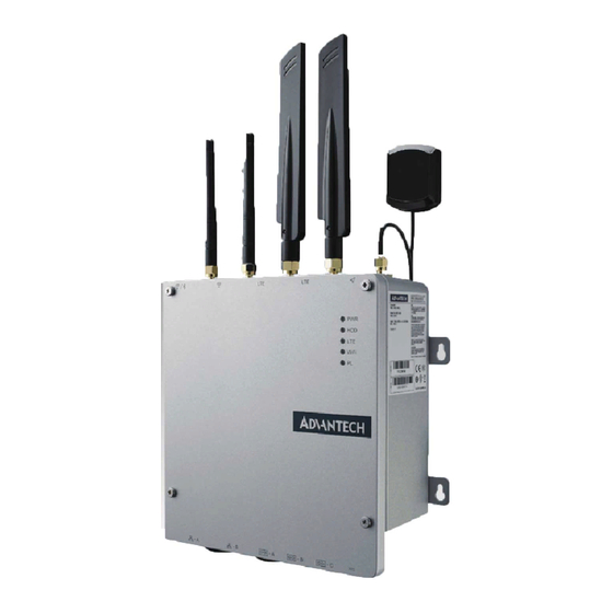
- Page 1 User Manual UNO-430 電腦 UNO-430-E1A ® Intel Atom Waterproof Gateway with All-Around IP69K/IP68 Rating...
- Page 2 No part of this manual may be reproduced, copied, translated or transmitted in any form or by any means without the prior written permission of Advantech Co., Ltd. Information provided in this manual is intended to be accurate and reliable. How- ever, Advantech Co., Ltd.
- Page 3 Because of Advantech’s high quality-control standards and rigorous testing, most of our customers never need to use our repair service. If an Advantech product is defec- tive, it will be repaired or replaced at no charge during the warranty period. For out- of-warranty repairs, you will be billed according to the cost of replacement materials, service time and freight.
- Page 4 這是甲類測試產品,在居住的環境中使用時,可能會造成射頻干擾,在這種情況下, 使用者會被要求採取某些適當的對策。 Technical Support and Assistance Visit the Advantech web site at www.advantech.com/support where you can find the latest information about the product. Contact your distributor, sales representative, or Advantech's customer service center for technical support if you need additional assistance. Please have the following information ready before you call: –...
- Page 5 ES1, rated 10-36Vdc, 3-0.83A minimum to match the unit rating, if need further assistance, please contact Advantech for further information. DISCLAIMER: This set of instructions is given according to IEC 704-1. Advantech disclaims all responsibility for the accuracy of any statements contained herein.
- Page 6 Safety Instructions Lire attentivement les instructions de sécurité. Conserver ce manuel pour utilisation ultérieure. Débranchez cet équipement de toute prise secteur avant de le nettoyer. Utilisez seulement un chiffon humide. N'utilisez pas de détergent liquide ou pulvérisé pour le nettoyage. Placez cet équipement sur une surface fiable pendant l'installation.
- Page 7 安全指示 請仔細閱讀此安全操作說明。 請妥善保存此用戶手冊供日後參考。 用濕抹布清洗設備前,請確認拔除電源線。請勿使用液體或去污噴霧劑清洗設 備。 對於使用電源線的設備,設備周圍必須有容易接觸到的電源插座。 請在安裝前確保設備放置在可靠的平面上,意外摔落可能會導致設備損壞。 當您連接設備到電源插座前,請確認電源插座的電壓符合要求。 請將電源線佈置在人們不易絆倒的位置,請勿在電源線上覆蓋任何雜物。 請注意設備上所有的警告標示。 如果長時間不使用設備,請拔除與電源插座的連結,避免設備被超標的電壓波動 損壞。 請勿自行打開設備。為了確保您的安全,請透過經認證的工程師來打開設備。 如遇下列情况,請由專業人員維修: 電源線或插頭損壞; 設備內部有液體流入; 設備無法正常工作,或您無法透過用戶手冊來正常工作; 設備摔落或損壞; 設備有明顯外觀損; 請勿將設備放置在超出建議溫度範圍的環境,即不要低於-40°C(-40°F)或 高於85°C(185°F),否則可能會造成設備損壞。 注意:若電池更換不正確,將有爆炸危險。因此,只可以使用製造商推薦的同一 種或者同等型號的電池進行替換。請按照製造商的指示處理舊電池。 本產品於國內裝置使用時,其電源僅限使用機架電源模組所提供直流電源輸入, 不得使用交流電源及附加其他電源轉換裝置提供電源,其電源輸入電壓及電流請 依說明書規定使用。 根據IEC 704‐1:1982 規定,操作員所在位置音量不可高於70 分貝。 限制區域:請勿將設備安裝於限制區域使用。 免責聲明:請安全訓示符合IEC 704‐1 要求。研華公司對其內容之準確性不承 擔任何法律責任。 UNO-430 User Manual...
- Page 8 Warnings, Cautions and Notes Warning! Warnings indicate conditions, which if not observed, can cause personal injury! Caution! Cautions are included to help you avoid damaging hardware or losing data. e.g. There is a danger of a new battery exploding if it is incorrectly installed. Do not attempt to recharge, force open, or heat the battery.
-
Page 9: Table Of Contents
Contents Chapter Overview..........1 Introduction ....................2 Safety Precautions ..................2 Packing List....................3 Hardware Specifications ................3 1.4.1 General ..................3 Chipset ...................... 4 1.5.1 Functional specification..............4 Mechanical Specifications................. 5 1.6.1 Dimensions ................... 5 Figure 1.1 Dimensions..............5 1.6.2 Weight................... - Page 10 Table 2.8: M.2 E Key Connector Pin Assignments ....17 2.3.2 Internal maintenance I/O ............19 Figure 2.13USB 2.0 Connector ..........20 Table 2.9: USB 2.0 Connector Pin Assignments....... 20 Figure 2.14USB 3.0 Connector ..........20 Table 2.10:USB 3.0 Connector Pin Assignments....... 20 Figure 2.15DisplayPort Connector ..........
-
Page 11: Chapter 1 Overview
Chapter Overview This chapter provides an overview of UNO-430 specifications. Sections include: Introduction Hardware specification Chassis dimensions... -
Page 12: Introduction
Introduction Designed for use in harsh industrial environments, UNO-430 features all-around IP69K/68-rated ingress protection and cable gland I/O connectors to provide a truly watertight solution that can withstand the most demanding applications. The water- proof enclosure features a front door for easy access and maintenance as well as a cable gland that offers further ingress protection, reducing the need for waterproof cables and wiring. -
Page 13: Packing List
Packing List Please refer to below packing list: UNO-430 1 x 1x3 Plug-in block for power wiring 2 x Mounting Kit 4 x M4x6L screws for Mounting Kit installation Quick Start Guide Simplified Chinese manual ... -
Page 14: Chipset
Chipset 1.5.1 Functional specification 1.5.1.1 Processor Processor Intel® Atom Quad Core E3950 2GHz processor 1.5.1.2 Chipset Memory Supports DDR3L 1333 MHz (without ECC) SODIMM Socket – 260-pin SODIMM socket Processor Graphics Intel® HD Graphics 505 M.2 Interface 1 x M.2 (Type 2242) key B support (OS storage and boot) ... -
Page 15: Mechanical Specifications
Mechanical Specifications 1.6.1 Dimensions Figure 1.1 Dimensions 1.6.2 Weight 3.0 kg UNO-430 User Manual... -
Page 16: Power Requirements
Power Requirements 1.7.1 System power DC 10-36VDC 1.7.2 RTC battery BR2032 3 V/200 mAh Environment Specification 1.8.1 Operating temperature -40 ~ 70°C (-40 ~ 158°F) @ 5 ~ 85% RH with 0.7 m/s airflow 1.8.2 System safety certification test temperature -40 ~ 70°C with M.2 SSD 1.8.3 Relative humidity... -
Page 17: Chapter 2 H/W Installation
Chapter H/W Installation This chapter introduces external IO and the installation of UNO-430 hardware. -
Page 18: Introduction
Introduction The following sections show the internal jumper settings and the external connectors and pin assignments. Figure 2.1 Motherboard Connector and jumper locations (top side) Figure 2.2 Motherboard Connector and jumper locations (rear side) UNO-430 User Manual... - Page 19 Table 2.1: Motherboard Connector Location Function Location Function Memory slot CN9018 Debug port Displayport CN9020 12V DC Input CN27 USB3.0 CN9935 DC Output M.2 B key for 2242 CN9028 Coaxial PCIe signal storage CN19 Figure 2.3 IO board connector locations Table 2.2: IO Board Connector Location Function...
-
Page 20: Jumper And Switch
Jumper and Switch Table 2.3: Jumper and Switch List Location Function CN1(motherboard) Clear CMOS SW1 (I/O board) RS-232 console mode function setting 2.2.1 Clear CMOS Configure the UNO-430 to match the needs of your application by setting jumpers. To close a jumper, you connect the pins with the clip. To open a jumper, you remove the clip. -
Page 21: Connectors
Footprint 3x1 Pin Setting Function console (1-2) Normal (2-3) Console mode (default) Connectors 2.3.1 I/O Connectors Wi-Fi/BT SMA connector GPS SMA connector LTE SMA connector Figure 2.4 UNO-430 Top I/O View Storage Wi-Fi Programmable Figure 2.5 UNO-430 Front LED View M12 cable gland M32 cable gland Figure 2.6 UNO-430 Bottom I/O View... - Page 22 Screws reserved for MultiTech Dragonfly card M32 cable gland M12 cable gland M.2 E-key for Wi-Fi M.2 B-key for LTE/5G USB 3.0 DP 1.2 Standard SIM card slot Power connector M.2 B-key for storage RS-422/485 RJ45 LAN RS-232 (console) USB 2.0 Figure 2.7 UNO-430 Box open I/O View 2.3.1.1 SMA Connector...
- Page 23 2.3.1.3 COM Connector The UNO-430 features 1 x RS232 (console) and 2 x 422/485 (isolated) ports in termi- nal block type, RS-232 (console) can enable/disable remote control function by switch. You can find detailed setting methods in Chapter 2.2.2. Figure 2.8 COM Connector Figure 2.9 COM Connector Pin Assignments 2.3.1.4 Power Connector...
- Page 24 Figure 2.11 Power Connector Pin Assignments 2.3.1.5 LAN Connector UNO-430 is equipped with two Gigabit LAN controllers. An Intel® i210 Ethernet con- troller that complies with IEEE 802.3u 10/100/1000 Base-T is used as the controller chip. The Ethernet port is a standard RJ-45 jack. Additionally, LED indicators are pro- vided on the front of the device to indicate the system's Link (off/green/orange) and Active (green) status.
- Page 25 Table 2.5: LED Indicators Left LED Right LED 10 Link 100 Left 1000 Link Active Orange Green Orange 2.3.1.6 SIM Slot There’s one standard SIM Slot for supporting LTE function, labeled “CN5” on I/O board. In addition to install SIM card on “CN5”, users are required to install a LTE Module on“CN7”...
- Page 26 Table 2.6: M.2 B Key Connector Pin Assignments SATA1_RX+ SATA1_RX- SATA1_C_TX- SATA1_C_TX+ PMU_SUSCLK +V3.3 +V3.3 +V3.3 IO board M.2 B-key 3042/3052 LTE Connector (CN7) Table 2.7: M.2 B Key Connector Pin Assignments Signal Name Signal Name 3V_LTE 3V_LTE M2_LTE_PWR_ON M2_LTE_USB_DP M2_LTE_W1_DISABLE_N M2_LTE_USB_DN M2_LTE_LED_WWAN#...
- Page 27 Table 2.7: M.2 B Key Connector Pin Assignments USB_Z_SSRX1+ M2_SIM1_CLK M2_SIM1_DATA USB_Z_SSTX1- M2_SIM1_PWR USB_Z_SSTX1+ M2_SIM2_DET PCIE_A_X_RX3- PCIE_A_X_RX3+ PCIE_A_X_TX3- M2_SIM2_PWR PCIE_A_X_TX3+ LTE_RST_GPIO# MPCIE_CLKREQ# CLK_LAN1_PCIE PCIE_WAKE# CLK_LAN1_PCIE+ M2_SIM1_DET LTE_RST_GPIO# 3V_LTE 3V_LTE 3V_LTE IO board M.2 E-key 2230 WiFi Connector (CN8) Table 2.8: M.2 E Key Connector Pin Assignments Signal Name Signal Name +V3.3_MINI...
- Page 28 Table 2.8: M.2 E Key Connector Pin Assignments Mechanical notch E Mechanical notch E Mechanical notch E Mechanical notch E Mechanical notch E Mechanical notch E Mechanical notch E Mechanical notch E USB_Z_SSTX1- USB_Z_SSTX1+ PCIE_A_X_RX3- PCIE_A_X_RX3+ PCIE_A_X_TX3- PCIE_A_X_TX3+ M2_SYSCLK WIFI_PLTRST# CLK_LAN1_PCIE BT_ DISABLE_L CLK_LAN1_PCIE+...
-
Page 29: Internal Maintenance I/O
Storage Wi-Fi Programmable 2.3.2 Internal maintenance I/O UNO-430 User Manual... - Page 30 2.3.2.1 USB connector UNO-430 provides 1 x USB 3.0 and 1 x USB2.0 interface connectors, which give complete Plug & Play and hot swapping for up to 127 external devices. The USB interface complies with USB XHCI, Rev. 3.0. Please refer to the table below for pin assignments.
-
Page 31: Chassis Grounding
2.3.2.2 DisplayPort Connector UNO-430 provides a high resolution DisplayPort, It supports display resolution of up to 4096x2160@60Hz. Figure 2.15 DisplayPort Connector Table 2.11: DisplayPort Adaptor Cable Pin Assignments Signal Name ML_Lane 0 (p) ML_Lane 0 (n) ML_Lane 1 (p) ML_Lane 1 (n) ML_Lane 2 (p) ML_Lane2 (2) ML_Lane 3 (p) -
Page 32: Installation
Installation 2.5.1 Cable gland installation UNO-430 provides four M12 cable glands (COM A / COM B / COM C / Power) and two M32 cable glands (LAN A / LAN B) to support easy wiring/connecting to the inner terminal block and RJ45 connectors. UNO-430 supports four M12 and two M32 cable glands installation. - Page 33 Push rubber seal into UNO-430 bottom hole and use wrench to tighten hexago- nal outer cable gland with defined torque value. Note: M32 cable glands (Advantech P/N: 1655006057-01) defined torque value is 18~20 kgf.cm M12 cable glands (Advantech P/N: 1655006056-01) defined torque value is 3~5 kgf.cm UNO-430 User Manual...
-
Page 34: Storage Installation (Optional)
Follow step 2 to step 4 to finish M12 cable gland assembling. 2.5.2 M.2 Storage installation (Optional) UNO-430 supports 1 M.2 (Type 2242) B key storage installation. The following steps demonstrate how to install M.2 storage. Remove 4 screws from top cover of UNO-430 then you can open it. Remove 6 screws form shielding case on main board. -
Page 35: Wifi/Lte Module Installation (Optional)
Install the M.2 storage and fix the screw Recover the shielding case on main board and top cover and fix the screws. 2.5.3 M.2 WIFI/LTE Module Installation (Optional) UNO-430 supports 1 M.2 (Type 3052/3042) key B for 5G/LTE module installation and M.2 (Type 2230) key E for WIFI/Bluetooth module installation. - Page 36 Install the M.2 2230 WIFI (position )/ M.2 3042 LTE or 3052 5G module (posi- tion ) and fix the screw. Note! Please adjust the right placement to fix the bracket for M.2 3042/3052 module. The SMA Antenna cables are default for UNO-430. Connect the MHF of Antenna cable with module.
-
Page 37: Antenna Installation (Optional)
Please remove caps from SMA connector and install specific Antenna on each SMA connectors. Wi-FI Antenna P/N: 1751000018-01 LTE Antenna P/N: 1751000017-01 GPS Antenna P/N: 1751000044-01 Note! Wireless Module, Antenna are optional, please contact Advantech for further information. UNO-430 User Manual... -
Page 38: Mounting Kit Installation (Optional)
2.5.5 Mounting kit Installation (Optional) Wall Mounting Fix the mounting kits with 4 (M4x6L) screws Mounting kit P/N: 1960095178N001 Note! Can an only be used in fixed position with antenna facing upward when in outdoor environments. UNO-430 User Manual... -
Page 39: Ami Bios Setup
Appendix AMI BIOS Setup This chapter introduces how to set BIOS configuration data. -
Page 40: Tpm 2.0 Bios Setting
TPM 2.0 BIOS Setting The UNO-430 systems support TPM2.0 functionality. This can be enabled or dis- abled in the BIOS menu by following the instructions provided below. Power on the UNO-430 system and press "Delete" to enter the BIOS configura- tion menu. -
Page 41: Cpu Turbo Mode Bios Setting
CPU Turbo mode BIOS Setting The UNO-430 systems support CPU Turbo mode. This can be enabled or disabled in the BIOS menu by following the instructions provided below Power on the UNO-137 system and press “Delete” to enter the BIOS configura- tion menu. - Page 42 Choose "enable/disable" to enable or disable the CPU Turbo mode (The default setting is to disable this function). UNO-430 User Manual...
-
Page 43: Rs-232 Console Port Setting
Appendix RS-232 Console Port Setting... - Page 44 The RS-232 console redirection has already been enabled in the BIOS by default. User can easily connect to UNO-430 by using “PUTTY” or other SSH tool. Download and install PUTTY https://www.putty.org/ in your device. Connect the RS-232 cable to UNO-430 COM1. Open PUTTY, set COM 1 and 115200.
- Page 45 Note! The console port over serial port is not enabled in some Linux distribu- tion, user has to manually enable it. We take ubuntu18.04 as example, ubuntu18.04 is already installed in UNO-430, but console port is not enabled. Change GRUB terminal to console and ttyS0. This will provide one GRUB to a ...
- Page 46 Execution result UNO-430 User Manual...
- Page 47 UNO-430 User Manual...
- Page 48 No part of this publication may be reproduced in any form or by any means, electronic, photocopying, recording or otherwise, without prior written permis- sion of the publisher. All brand and product names are trademarks or registered trademarks of their respective companies. © Advantech Co., Ltd. 2021...
Need help?
Do you have a question about the Intel UNO-430-E1A and is the answer not in the manual?
Questions and answers