
Related Manuals for Advantech UNO-420


Summary of Contents for Advantech UNO-420
- Page 1 User Manual UNO-420 工業用網關 Intel® Atom™ PoE Powered Device Sensing Gateway with 3 x COM, 2 x LAN(1 x PoE), 8 x GPIO, HDMI, USB3.0...
- Page 2 No part of this manual may be reproduced, copied, translated or transmitted in any form or by any means without the prior written permission of Advantech Co., Ltd. Information provided in this manual is intended to be accurate and reliable. How- ever, Advantech Co., Ltd.
- Page 3 Because of Advantech’s high quality-control standards and rigorous testing, most of our customers never need to use our repair service. If an Advantech product is defec- tive, it will be repaired or replaced at no charge during the warranty period. For out- of-warranty repairs, you will be billed according to the cost of replacement materials, service time and freight.
- Page 4 這是甲類測試產品,在居住的環境中使用時,可能會造成射頻干擾,在這種情況下, 使用者會被要求採取某些適當的對策。 Technical Support and Assistance Visit the Advantech web site at www.advantech.com/support where you can find the latest information about the product. Contact your distributor, sales representative, or Advantech's customer service center for technical support if you need additional assistance. Please have the following information ready before you call: –...
- Page 5 The sound pressure level at the operator's position according to IEC 704-1:1982 is no more than 70 dB (A). DISCLAIMER: This set of instructions is given according to IEC 704-1. Advantech disclaims all responsibility for the accuracy of any statements contained herein.
- Page 6 電源線或插頭損壞; 設備內部有液體流入; 設備曾暴露在過度潮濕環境中使用; 設備無法正常工作,或您無法透過用戶手冊來正常工作; 設備摔落或損壞; 設備有明顯外觀損; 15. 請勿將設備放置在超出建議溫度範圍的環境,即不要低於 -40°C (-40°F)或 高於 80°C (180°F) ,否則可能會造成設備損壞。 16. 注意:若電池更換不正確,將有爆炸危險。因此,只可以使用製造商推薦的同一 種或者同等型號的電池進行替換。請按照製造商的指示處理舊電池。 17. 根據 IEC 704‐1:1982 規定,操作員所在位置音量不可高於 70 分貝。 18. 限制區域:請勿將設備安裝於限制區域使用。 19. 免責聲明:請安全訓示符合 IEC 704‐1 要求。研華公司對其內容之準確性不承 擔任何法律責任。 UNO-420 User Manual...
-
Page 7: Table Of Contents
Power Button/Power Management ..........8 2.2.8 Reset Button ................. 8 2.2.9 PCI Express Mini Card Socket............8 Figure 2.4 The UNO-420 supports 1x full size mPCIe slot (CN11), and 1x half size mPCIe slot (CN10) ......8 Chapter Initial Setup ..........9 Connecting Power................... - Page 8 Table A.5: GPIO-port pin definition details ........ 30 UNO-420 User Manual viii...
-
Page 9: Chapter 1 Overview
Chapter Overview This chapter provides an overview of UNO-420 specifications. Sections include: Introduction Safety precautions Accessories... -
Page 10: Introduction
3 x COM port, 2 x LAN port (one with Power Over Ethernet (PoE) technology), and 8 x GPIO. The UNO-420 can operate in wide temperatures (from -20 to 60°C). The UNO-420 uses Intel Atom CPUs and built-in onboard 2G DDR3L RAM for heavy programs. -
Page 11: Accessories
Power Consumption: 12 W (Typical), 20 W (Max) Software OS: Ubuntu Linux, Windows 10 2019 LTSC Applicable Models: UNO-420, UNO-420-E0A, UNO-420-E1A, UNO-420-E2A, UNO-420-E3A, UNO-421-E0A, UNO-421-E0A, UNO-421-E1A, UNO-421-E2A, UNO-421-E3A, UNO420E0A1901-T, UNO420E0A1902-T, UNO420E0A1903-T, UNO420E0A2001-T, UNO420E0A2002-T, UNO420E0A2003-T, UNO421E0A1901-T, UNO421E0A1902-T, UNO421E0A1903-T, UNO421E0A2001-T, UNO421E0A2002-T,... - Page 12 UNO-420 User Manual...
-
Page 13: Chapter 2 Hardware Functionality
Chapter Hardware Functionality This chapter shows how to setup the UNO-420’s hardware func- tions, including connecting peripherals, setting switches and indicators. Sections include: Introduction UNO-420 Interface LAN: Ethernet Connector Serial Connector GPIO Connector Power Connector ... -
Page 14: Introduction
Introduction The following figures show the connectors on UNO-420. The following sections give you information about each peripheral. Figure 2.1 Left side view of UNO-420 Figure 2.2 Bottom view of UNO-420 Figure 2.3 Right side view of UNO-420 UNO-420 User Manual... -
Page 15: Uno-420 Interface
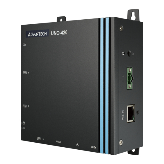
UNO-420 Interface The UNO-420 PoE Powered Device Sensing Gateway with 3 x COM, 2 x LAN (1 x PoE), 8 x Programmable GPIO, HDMI, USB3.0. 2.2.1 LAN: Ethernet Connector UNO-420 is equipped with two Gigabit LAN controller. For the UNO-420, the control- ler chip used is an Realtek RTL8119E Ethernet controller that is fully compliant with IEEE 802.3u 10/100/1000 Base-T. -
Page 16: Power Button/Power Management
2.2.7 Power Button/Power Management Press the “PWR” button to power on or power off the UNO-420(ATX type). The UNO- 420 supports the ACPI (Advanced Configuration and Power Interface). Besides power on/off, it support multiple suspend modes, such as Power on Suspend (S1), Suspend to RAM (S3), Suspend to Disk (S4). -
Page 17: Chapter 3 Initial Setup
Chapter Initial Setup This chapter introduces how to initialize the UNO-420. Sections include: Connecting Power Installing Wireless LAN Card and Antenna Assembling Din-rail / Wall mounting Reassign COM Port Number... -
Page 18: Connecting Power
This product is intended to be supplied by a Listed Power Adapter or DC power source, rated at 10-30Vdc, 2A and Tma 60 degree C, if you need further assistance, please contact Advantech for further information. Installing a Wireless LAN Card and Antenna Loosen screws x 5. - Page 19 Assemble SMA socket to correspond SMA slot, then plug SMA cable onto wire- less module. Fasten 5 x screws UNO-420 User Manual...
-
Page 20: Mounting Type: Din-Rail
Assemble antenna. Mounting type: Din-rail Mounting type: Wall-mount UNO-420 User Manual... -
Page 21: Reassign Com Port Number
Reassign COM Port Number Use "Reassign COMNo Utility" to modify COM Port sequence. Run ReAssignCOMPortNumb.exe UNO-420 User Manual... - Page 22 Download and install Net Framework v3.5 while connected to the network. Wail until feature successfully installed. UNO-420 User Manual...
- Page 23 Modify COM3 to COM1 Modify COM4 to COM2 UNO-420 User Manual...
- Page 24 Modify COM5 to COM3 Click on "Exit" once finish setting UNO-420 User Manual...
-
Page 25: Ami Bios Setup
The Setup program uses a number of menus for making changes and turning special features on or off. This chapter describes the basic navigation of the UNO-420 setup screens. 2. Entering Setup Press the "Del" or "Esc." key during the Power On Self Test (POST) process to enter the BIOS setup screen, otherwise the system will continue the POST process. - Page 26 When you first enter the BIOS Setup Utility, you will enter the Main setup screen. You can always return to the Main setup screen by selecting the Main tab. There are two Main Setup options. They are described in this section. The Main BIOS Setup screen is shown below. UNO-420 User Manual...
- Page 27 – OS Selection This item allows the user to set the OS mode: "Ubuntu linux" or "Windows 10" Once selection done, click on "Esc" then click on "Save & Exit" to save the setting. 5. Super IO Configuration UNO-420 User Manual...
- Page 28 UNO-420 supports 2xRS-232/422/485 & 1-RS-485. Serial Port Configuration – Serial Port Termination This item allows users to enable or disable for "Serial Port". – Device Mode This item allows users to set the mode to RS-422/485. The default setting is "RS232".
-
Page 29: Gpio Programming Guide
GPIO Programming Guide Click on start up icon on Windows, go Advantech folder then select "Auxiliary IO test utility command selection" UNO-420 User Manual... - Page 30 Type in command "AuxIO.exe". It will show information of command type, defini- tion and examples. UNO-420 User Manual...
-
Page 31: System Settings And Pin Assignments
Appendix System Settings and Pin Assignments... -
Page 32: System I/O Address And Interrupt Assignment
IRQ15 Reserved Board Connectors and Jumpers There are several connectors and jumpers on the UNO-420 board. The following sections tell you how to configure the UNO-420 hardware setting. Figure A.1 shows the locations of UNO-420’s connectors and jumpers. Figure A.1 Connector & Jumper Locations for UNO-420 (front) -
Page 33: Power Connector (Pwr)
COM1/COM2 Hi / Low Resistor setting COM3 Termination Resistor setting Clear CMOS switch PWR1 Power button RST1 Reset button Power Connector (PWR) Table A.3: Power connector pin assignments Signal Description Power IN V+ 10 ~ 30V Power IN V- (GND) UNO-420 User Manual... -
Page 34: Hdmi Display Connector
TMDS Data0+ TMDS Data0 Shield TMDS Data0- TMDS Clock+ TMDS Clock Shield TMDS Clock- Reserved DDC/CEC/HEC Ground +5 V Power (max 50 mA) Hot Plug Detect COM1/COM2 RS232/422/485 connector D-SUB Conn. 9P 90D(M) DIP RS232 RS422 RS485 UNO-420 User Manual... -
Page 35: Com3 Rs-485 Connector
W_DISA in cards that implement Reserved BLE# radio frequency applications. When implemented, this sig- nal requires a pull-up resis- tor on the card. Reserved REFCLK+ UNO-420 User Manual... - Page 36 +3.3Vaux pended state to service a function initiated wake event. * +3.3Vaux was suspend Power , power out to device +3.3V/1.1A * +3.3V was core power * +1.5V was core power, power out to device +1.5V/0.5A UNO-420 User Manual...
-
Page 37: Lan Rj45 Connector
1000BASE-T: In MDI and in MDI-X configuration, MDI[2]+/- corresponds to BI_DC+/- and MDI[3]+/- corre- MDI2- sponds to BI_DD+/-. 100BASE-TX: Unused. MDI3+ 10BASE-T: Unused. MDI3- Right LED Left LED 10Link 100Link 1000 Link Active Orange Green Green UNO-420 User Manual... -
Page 38: Gpio Connector
The GPIO port is powered by analog devices' AD5593R. Each pin has a 100K OHM series resistor between the connector and the AD5593R. Caution! This port is ESD-sensitive. An insulated GPIO connector that prevents direct ESD exposure to the I/O pins is recommended. UNO-420 User Manual... - Page 39 UNO-420 User Manual...
- Page 40 No part of this publication may be reproduced in any form or by any means, electronic, photocopying, recording or otherwise, without prior written permis- sion of the publisher. All brand and product names are trademarks or registered trademarks of their respective companies. © Advantech Co., Ltd. 2019...
Need help?
Do you have a question about the UNO-420 and is the answer not in the manual?
Questions and answers