Table of Contents
Advertisement
Quick Links
Download this manual
See also:
User Manual
Advertisement
Table of Contents

Subscribe to Our Youtube Channel
Related Manuals for Advantech UNO-1251G


Summary of Contents for Advantech UNO-1251G
- Page 1 User Manual UNO-1251G 嵌入式工業電腦 ® ® Coretex -A8 Micro DIN- Rail Industrial IoT gateway w/ 2 x LAN, 1 x USB, 1 x CAN, 3 x COM, 2 x MicroSD, 1 x MicroSIM...
- Page 2 No part of this manual may be reproduced, copied, translated or transmitted in any form or by any means without the prior written permission of Advantech Co., Ltd. Information provided in this manual is intended to be accurate and reliable. How- ever, Advantech Co., Ltd.
-
Page 3: Declaration Of Conformity
Because of Advantech’s high quality-control standards and rigorous testing, most of our customers never need to use our repair service. If an Advantech product is defec- tive, it will be repaired or replaced at no charge during the warranty period. For out- of-warranty repairs, you will be billed according to the cost of replacement materials, service time and freight. - Page 4 Technical Support and Assistance Visit the Advantech web site at www.advantech.com/support where you can find the latest information about the product. Contact your distributor, sales representative, or Advantech's customer service center for technical support if you need additional assistance.
-
Page 5: Safety Instructions
The sound pressure level at the operator's position according to IEC 704-1:1982 is no more than 70 dB (A). DISCLAIMER: This set of instructions is given according to IEC 704-1. Advantech disclaims all responsibility for the accuracy of any statements contained herein. - Page 6 Note 2:“ ○ ” indicates that the percentage content of the restricted substance does not exceed the percentage of reference value of presence 備考 3. 〝-〞係指該項限用物質為排除項目。 Note 3:The “−” indicates that the restricted substance corresponds to the exemption UNO-1251G User Manual...
- Page 7 設備內部有液體流入; 設備曾暴露在過度潮濕環境中使用; 設備無法正常工作,或您無法透過用戶手冊來正常工作; 設備摔落或損壞; 設備有明顯外觀損; 請勿將設備放置在超出建議溫度範圍的環境,即不要低於 ‐20 ℃ (‐4 ℉)或高於 60 否則可能會造成設備損壞。 ℃ (140 ℉) , 16. 注意:若電池更換不正確,將有爆炸危險。因此,只可以使用製造商推薦的同一種或 者同等型號的電池進行替換。請按照製造商的指示處理舊電池。 17. 根據 IEC 704‐1:1982 規定,操作員所在位置音量不可高於 70 分貝。 18. 限制區域:請勿將設備安裝於限制區域使用。 19. 免責聲明:請安全訓示符合 IEC 704‐1 要求。研華公司對其內容之準確性不承擔任何 法律責任。 UNO-1251G User Manual...
- Page 8 UNO-1251G User Manual viii...
-
Page 9: Table Of Contents
Chapter Hardware Functionality .......5 Introduction ....................6 Figure 2.1 Front Panel of UNO-1251G ........6 Figure 2.2 Top Panel of UNO-1251G .......... 6 Figure 2.3 Bottom Panel of UNO-1251G ........6 Figure 2.4 Left Panel of UNO-1251G .......... 7 Serial Connections ..................7 2.2.1... - Page 10 Switch setting of CAN port ..............21 Power Connector ..................22 Table A.5: Connectors and Jumpers ......... 22 USB Connector ..................22 Table A.6: Connectors and Pin Assignments ......22 LAN Connector ..................23 Table A.7: Connectors and Pin Assignments ......23 UNO-1251G User Manual...
-
Page 11: Chapter 1 Overview
Chapter Overview This chapter provides an overview of UNO-1251G specifications. Sections include: Introduction Safety precautions Accessories... -
Page 12: Introduction
SIM slot. With WebAccess/HMI sup- port, it is compatible with 450 types of PLC, controllers & I/O devices. User can easily access UNO-1251G through mobile devices by VNC. It is the ideal solution for auto- mation control as a cloud enabled HMI platform. -
Page 13: Safety Precautions
Warning! Toujours à la terre pour éliminer toute charge d'électricité statique avant toucher UNO-1251G. Appareils électroniques modernes sont très sensi- bles à charges d'électricité statique. Utilisez un bracelet antistatique à tout moment. Placez tous composants électroniques sur une surface antistatique ou dans un statique-sac blindé. -
Page 14: Accessories
Accessories Please refer below for the accessory list: 4-pin phoenix connector for power wiring (Advantech P/N: 1652000292) 10-pin phoenix connector for COM1/COM2/Console port (Advantech P/N: 1652005896) 3-pin phoenix connector for CAN port (Advantech P/N: 1652000049) Din-Rail Mounting kit (Advantech P/N: 1960018849T021) ... -
Page 15: Chapter 2 Hardware Functionality
Chapter Hardware Functionality This chapter shows the UNO- 1251G’s hardware functions, including: Introduction Serial connections Ethernet LAN Connector LED Indicators OLED indicators Power connector USB connector CAN port Reset Button Antenna Mounting ... -
Page 16: Introduction
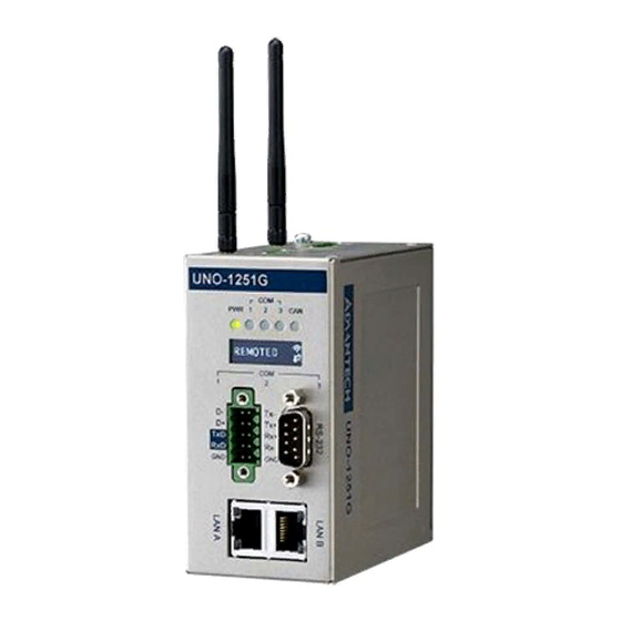
Introduction The following figures show the panel configuration on UNO-1251G. More information of each peripheral is included in the following sections. Figure 2.1 Front Panel of UNO-1251G Figure 2.2 Top Panel of UNO-1251G Figure 2.3 Bottom Panel of UNO-1251G UNO-1251G User Manual... -
Page 17: Serial Connections
2.2.1 Serial Mode and Terminator Resistor Selection UNO-1251G provides 3 serial Com ports, COM1 provide RS-485, COM2 provides RS-422/485 and COM3 provides RS-232. The default setting of COM2 is RS-422. Users could change COM2 Port serial types to RS-422 or RS-485 by SW7 DIP switch selection. -
Page 18: Debug Port
LED Indicators There are four LEDs indicating the status of the system power, serial and CAN are located on the front panel of UNO-1251G, and each of them has its own specific meaning, as shown in the table below. PWR: Green light means normal ... -
Page 19: Usb Connector
The USB interface supports Plug and Play, which enables you to connect or discon- nect a device whenever you want, without turning off the computer. The UNO-1251G provides one connector of USB interfaces, which gives complete Plug & Play and hot swapping for up to 127 external devices. -
Page 20: Micro Sim Card Slot
2.12 Micro SIM card Slot There is one externally accessible micro SIM card slot on UNO-1251G. User can insert standard micro-SIM card from the bottom panel shown in Figure 2.3. 2.13 PCI Express Mini Card Socket The UNO-1251G supports one full-size PCI Express Mini (mPCIe) card expansion, refer to Figure 2.4. -
Page 21: Chapter 3 Initial Setup
Chapter Initial Setup This chapter introduces how to initialize the UNO-1251G. Sections include: Chassis Grounding Inserting a microSD/SIM card Installing a wireless module card and antenna Installing iDoor expansion I/O Din-rail kit assembly Conneting Power... -
Page 22: Chassis Grounding
Chassis Grounding The UNO-1251G is designed with EMI protection and a stable grounding base. There is an easy-to-connect chassis grounding point to use. Note that the system ground and chassis ground are separate. Figure 3.1 Chassis Grounding Connection Inserting a microSD card/microSIM card... -
Page 23: Installing A Wireless Module Card And Antenna (Optional)
Installing a Wireless module Card and Antenna (Optional) For optional wireless module card and antenna, please contact Advantech for the fol- lowing wireless solution kit. Top panel with pre-cut antenna holes The internal coaxial cable with standard SMA connector For more information about internal coaxial cable, please contact with Advantech. -
Page 24: Din-Rail Kit Assembly
Assemble the antenna(s) on the SMA connector. Din-rail Kit Assembly The UNO-1251G supports Din-rail mounting. The Din-rail kit and screws are included in the accessory bag. The assembly instruction is shown in Figure 3.2 below. Figure 3.2 UNO-1251G with Din-rail mounting... -
Page 25: Connecting Power
16 bit pixel size setting, to remotely access the UNO-1251G. Here is example using “.NET VNC Viewer” as VNC client. Set the IP address of PC (VNC client) to be the same domain as UNO-1251G. (10.0.0.X. X could be any digit excludes 1 & 2) Download “.NET VNC Viewer"... - Page 26 Press “OK” Embedded Linux version The UNO-1251G installed with embedded Linux could be also accessed by VNC cli- ent. The VNC tool could be ".NET VNC Viewer" or other VNC viewers. E.g. RealVNC viewer, TightVNC viewer and UltraVNC viewer, etc.
-
Page 27: System Settings And Pin Assignments
Appendix System Settings and Pin Assignments... -
Page 28: Board Connectors And Switches
Board Connectors and Switches There are several connectors and jumpers on the UNO-1251G board. The following sections tell you how to configure the UNO-1251G hardware setting. Figure A.1 shows the locations of UNO-1251G’s connectors and switches. Figure A.1 Connector & Switch Locations (front)) Table A.1: Connectors and Jumpers... -
Page 29: Rs-485 Serial Port (Com1), Rs-4222/485 Serial Port (Com2) And Console Port
Port (COM2) and console port Table A.2: Connectors and Jumpers Description COM2 RS-422 Rx Debug port Rx COM2 RS-422 Rx+ Debug port Tx COM2 RS-422 Tx+ or RS-485 Data+ COM1 RS-485 Data+ COM2 RS-422 Tx- or RS-485 Data- COM1 RS-485 Data- UNO-1251G User Manual... -
Page 30: Switch Setting Of Rs-485 Serial Port (Com1) & Rs-4222/485 Serial Port (Com2)
2. COM2 RS-422 mode (contact to Pin 5, 6, 7, 8) Termination resistor ON COM1 RS485: Contact to Pin 8, COM2 RS485: Contact to Pin 7, COM2 RS422 Tx: Contact to Pin 7, COM2 RS422 Rx: Contact to Pin 6 (if switch to termination resistor OFF, Contact to Pin 1, 2, 3) RS-422 master mode Contact to Pin 5 (if switch to RS-422 slave mode/RS-485, contact to Pin4) RS-232 Serial Port (COM3) Table A.3: Connectors and Jumpers Description UNO-1251G User Manual... -
Page 31: Can Port
CAN Port Table A.4: Connectors and Jumpers Description CAN_H CAN_L Switch setting of CAN port Description CAN termination resistor setting Default Termination resistor ON Termination resistor ON Contact to 2 (if switch to termination resistor OFF, Contact to Pin 1) UNO-1251G User Manual... -
Page 32: Power Connector
Power Connector Table A.5: Connectors and Jumpers Description 10~36 V+DC Input 1 10~36 V+DC Input 2 Power ground Chassis ground USB Connector Table A.6: Connectors and Pin Assignments Signal Name Description DATA- White DATA+ Green Black UNO-1251G User Manual... -
Page 33: Lan Connector
LAN Connector Table A.7: Connectors and Pin Assignments Signal Name XMT+ XMT- RCV+ RCV- UNO-1251G User Manual... - Page 34 No part of this publication may be reproduced in any form or by any means, electronic, photocopying, recording or otherwise, without prior written permis- sion of the publisher. All brand and product names are trademarks or registered trademarks of their respective companies. © Advantech Co., Ltd. 2016...
Need help?
Do you have a question about the UNO-1251G and is the answer not in the manual?
Questions and answers