Table of Contents
Advertisement
Quick Links
Advertisement
Table of Contents

Subscribe to Our Youtube Channel
Related Manuals for Aerotech A3200 Nmark GCL


Summary of Contents for Aerotech A3200 Nmark GCL
-
Page 1: Nmark Gcl Hardware Manual
Nmark GCL Hardware Manual Revision: 1.04.00 Patent Number: US 8,426,768 B2... - Page 2 This manual contains proprietary information and may not be reproduced, disclosed, or used in whole or in part without the express written permission of Aerotech, Inc. Product names mentioned herein are used for identification purposes only and may be trademarks of their respective companies.
-
Page 3: Table Of Contents
2.8. Encoder Input (TB103) 2.8.1. Emergency Stop Sense Input (TB103) 2.9. Switch S1 (Laser Output Polarity) 2.10. PC Configuration and Operation Information Chapter 3: Maintenance 3.1. Board Assembly 3.2. Preventative Maintenance Appendix A: Warranty and Field Service Appendix B: Revision History Index www.aerotech.com... -
Page 4: List Of Figures
Figure 2-21: Analog Outputs (TB102 B) Figure 2-22: Analog Inputs (TB102) Figure 2-23: Encoder Connections (TB103 A/B) Figure 2-24: ESTOP Sense Input (TB103) Figure 2-25: Switch S1 (Laser Output Polarity) Figure 3-1: Control Board Assembly Figure 3-2: Power Board Assembly www.aerotech.com... -
Page 5: List Of Tables
Mating Connector Part Numbers for the Encoder Interface Connector (TB103 A/B) Table 2-38: Nmark GCL to Drive Cable Part Numbers Table 2-39: TB103A ESTOP Pinout Table 2-40: Electrical Noise Suppression Devices Table 3-1: Control Board Fuse Specifications Table 3-2: Power Board Fuses Table 3-3: Preventative Maintenance www.aerotech.com... - Page 6 Table of Contents Nmark GCL Hardware Manual This page intentionally left blank. www.aerotech.com...
-
Page 7: Eu Declaration Of Conformity
Nmark GCL Hardware Manual Declaration of Conformity EU Declaration of Conformity Manufacturer Aerotech, Inc. Address 101 Zeta Drive Pittsburgh, PA 15238-2811 Product Nmark GCL Model/Types This is to certify that the aforementioned product is in accordance with the applicable requirements of the... -
Page 8: Agency Approvals
U8 16 06 68995 021 Standards: CAN/CSA-C22.2 No. 61010-1:2012; UL 61010-1:2012; EN 61010-1:2010 Visit https://www.tuev-sued.de/product-testing/certificates to view Aerotech's TÜV SÜD certificates. Type the certificate number listed above in the search bar or type "Aerotech" for a list of all Aerotech certificates. www.aerotech.com... -
Page 9: Safety Procedures And Warnings
N O T E : Aerotech continually improves its product offerings; listed options may be superseded at any time. All drawings and illustrations are for reference only and were complete and accurate as of this manual’s release. - Page 10 Nmark GCL Hardware Manual Electrical Safety This page intentionally left blank. www.aerotech.com...
-
Page 11: Quick Installation Guide
Section 2.3. FireWire Interface Digital / Analog I/O Section 2.7. Digital and Analog I/O (TB102 A/B) Galvo Connections Section 2.6. Galvo Connections (J201 and J202) Control Supply Section 2.2.1. Control Supply Connections (TB104) Motor Supply Section 2.2.2. Motor Supply Connections (TB201) www.aerotech.com... - Page 12 Quick Installation Guide Nmark GCL Hardware Manual This page intentionally left blank. www.aerotech.com...
-
Page 13: Chapter 1: Introduction
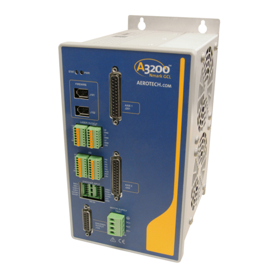
Introduction Chapter 1: Introduction Aerotech’s Nmark GCL, part of the A3200 product family, is a closed-loop scanner module that allows direct control of galvo scanner servo motion for marking parts of unlimited size and complexity. The Nmark GCL has support for CO2 and YAG lasers and includes Position Synchronized Output (PSO) laser firing based on real-time scanner positional feedback. -
Page 14: Figure 1-2: Functional Diagram
Introduction Nmark GCL Hardware Manual The following block diagram shows a connection summary (refer to Chapter 2 and Chapter 3 for more detailed connection information). Figure 1-2: Functional Diagram Chapter 1 www.aerotech.com... -
Page 15: Electrical Specifications
50-60 Hz Control Supply Inrush Current 16 A Input Current 0.35 A (max) Output Voltage 38 V Peak Output Current 20 A Continuous Output Current Minimum Load Resistance 0.5 Ω User Power Supply Output 5 VDC (@ 500 mA) www.aerotech.com Chapter 1... -
Page 16: Mechanical Design
Introduction Nmark GCL Hardware Manual 1.2. Mechanical Design The following figure shows the Nmark GCL package dimension as well as the typical mounting orientation. Figure 1-3: Dimensions Table 1-3: Unit Weight Weight 2.9 kg [6.4 lb] Chapter 1 www.aerotech.com... -
Page 17: Environmental Specifications
Decreasing linearly to 50% relative humidity at 40°C. Non condensing. Operating: 0 m to 2,000 m (0 ft to 6,562 ft) above sea level Altitude Contact Aerotech if your specific application involves use above 2,000 m or below sea level. Pollution Pollution degree 2 (normally only non-conductive pollution). -
Page 18: Drive And Software Compatibility
Drives that list a specific version number in the Last Software Version column will not be supported after the listed version. Table 1-4: Drive and Software Compatibility Drive Type Firmware Revision First Software Version Last Software Version 5.04 Current Nmark GCL 6.02 Current Chapter 1 www.aerotech.com... -
Page 19: Chapter 2: Installation And Configuration
Axis 1 parameters defined in the software. The drive assigned to the second com- munication channel will be configured by the Axis 2 parameters, etc. Table 2-1: Device Number Switch Settings Switch Settings (Off is indicated by "-") Device # Switch Location www.aerotech.com Chapter 2... -
Page 20: Power Connections
(#16 AWG) N O T E : Wire insulation rated for 300 V. Table 2-3: Control Supply Mating Connector (TB104) Screw Torque Wire Size: Type Aerotech P/N Phoenix P/N Value: Nm [AWG ] 3-Pin Terminal Block ECK00213 1754465 0.5 - 0.6 3.3 - 0.516 [12-30]... -
Page 21: Motor Supply Connections (Tb201)
2.1 mm (#14 AWG) N O T E : Wire insulation rated for 300 V. Table 2-5: Motor Supply Mating Connector (TB201) Screw Torque Wire Size: Type Aerotech P/N Phoenix P/N Value: Nm [AWG] 4-Pin Terminal Block ECK01581 1757035 0.5 - 0.6 3.3 - 0.0516 [12-30]... -
Page 22: External Power Supply Options
Switching power supplies must be rated for the peak current requirement of the application since they will typically shut down if overloaded. Figure 2-3: Control and Motor Power Wiring using a TM3 Transformer Chapter 2 www.aerotech.com... -
Page 23: Minimizing Conducted Radiated And System Noise
The shield of the cables must be connected to the metal back shell in order for the product to conform to radiated emission standards. The Nmark GCL is a component designed to be integrated with other electronics. EMC testing must be conducted on the final product configuration. www.aerotech.com Chapter 2... -
Page 24: Firewire Interface
0.9 m (3 ft) long, 6 pin to 6 pin NCONNECT-10000-GOF 10 m (32.8 ft), glass fiber optical cable NCONNECT-15000-GOF 15 m (49.2 ft), glass fiber optical cable NCONNECT-20000-GOF 20 m (65.6 ft), glass fiber optical cable NCONNECT-30000-GOF 30 m (101.7 ft), glass fiber optical cable Chapter 2 www.aerotech.com... -
Page 25: Laser / Pso Output (Tb101)
Laser Output 3 (5V TTL) Output Ground 5 Volt Power Supply (500 mA) Output Table 2-11: Laser Interface Connector Mating Connector (TB101) Wire Size: mm [AWG] Type Aerotech P/N Phoenix P/N 7-Pin Terminal Block ECK01631 1881370 0.5 - 0.080 [20-28] www.aerotech.com Chapter 2... -
Page 26: Figure 2-5: Laser Interface Outputs (Tb101)
Output Specifications (TB101) Specification Value Maximum Frequency 5 MHz Isolated Voltage 5 - 24 V Output Output Current ≤ 50 mA Maximum Frequency 10 MHz 5V TTL Voltage Output Current 50 mA Figure 2-5: Laser Interface Outputs (TB101) Chapter 2 www.aerotech.com... -
Page 27: Figure 2-6: Current Sinking Configuration (With Isolation)
Nmark GCL Hardware Manual Installation and Configuration Figure 2-6: Current Sinking Configuration (with Isolation) Figure 2-7: Current Sinking Configuration (without Isolation) www.aerotech.com Chapter 2... -
Page 28: Figure 2-8: Current Sourcing Configuration (With Isolation)
Installation and Configuration Nmark GCL Hardware Manual Figure 2-8: Current Sourcing Configuration (with Isolation) Figure 2-9: Current Sourcing Configuration (without Isolation) Chapter 2 www.aerotech.com... -
Page 29: Figure 2-10: Ttl Output
Nmark GCL Hardware Manual Installation and Configuration Figure 2-10: TTL Output www.aerotech.com Chapter 2... -
Page 30: Position Synchronized Output (Pso)
The optocoupler that you use on the output might have an effect on this rate. Table 2-14: PSO Output Pinout TB101 (A) Pin # Label Description In/Out/Bi Laser Output 1+ / PSO Output Output Laser Output 1- / PSO Output Output Chapter 2 www.aerotech.com... -
Page 31: Encoder Output (J103)
Axis 2 SIN+ Output Axis 2 COS+ Output Reserved Ground Table 2-16: Mating Connector Part Numbers for the Encoder Output Connector (J103) Mating Connector Aerotech P/N Third Party P/N 15-Pin D-Connector ECK00100 Amphenol DA15P064TXLF Backshell ECK01022 Amphenol 17E-1725-2 Figure 2-11: Encoder Outputs www.aerotech.com... -
Page 32: Figure 2-12: Pso External Sync Input
Installation and Configuration Nmark GCL Hardware Manual Table 2-17: PSO External Sync Specifications Specification Value Voltage 3.3 VDC Frequency 25 MHz Maximum On Time 20 ns Minimum Figure 2-12: PSO External Sync Input Chapter 2 www.aerotech.com... -
Page 33: Galvo Connections (J201 And J202)
Encoder Ground Frame Ground Motor - Output Motor - Output Table 2-19: Mating Connector Part Numbers for the Galvo Connector (J201 and J202) Mating Connector Aerotech P/N Third Party P/N 25-Pin D-Connector ECK00101 FCI DB25P064TXLF Backshell ECK00656 Amphenol 17E-1726-2 www.aerotech.com... -
Page 34: Analog Encoder Inputs (J201 And J202)
The Nmark GCL is designed to control the AGV Galvo motors which operate as DC Brush motors over a limited travel. The GCL must be factory-configured for the motor and cannot be used with any other motor types. Chapter 2 www.aerotech.com... -
Page 35: End Of Travel Limit Input Interface
Installation and Configuration 2.6.3. End of Travel Limit Input Interface Aerotech strongly recommends that you use End of Travel (EOT) limits to define the end of the physical travel. Current-based limits that are software-selectable through the EndOfTravelLimitSetup axis parameter can be used, but only if EOT limits are not available on your galvo motor. Positive or clockwise motion is stopped by the clockwise (CW) end of travel limit input. -
Page 36: Figure 2-13: End Of Travel Limit Input Connections
Installation and Configuration Nmark GCL Hardware Manual Figure 2-13: End of Travel Limit Input Connections Figure 2-14: End of Travel Limit Interface Input Chapter 2 www.aerotech.com... -
Page 37: End Of Travel Limit Phasing
CW and CCW inputs at the motor feedback connector or swap the CW and CCW limit functionality in the software using the EndOfTravelLimitSetup parameter. The logic level of the EOT limit inputs may be viewed in the diagnostic display (shown in Figure 2-15). Figure 2-15: Limit Input Diagnostic Display www.aerotech.com Chapter 2... -
Page 38: Thermistor Interface
As the increasing temperature causes the thermistor’s resistance to decrease, the signal will be seen as a logic low triggering an over temperature fault. The nominal trip value of the sensor is 2.4 kΩ. Table 2-22: Thermistor Interface Pinout Description In/Out/Bi Motor Over Temperature Thermistor Input Figure 2-16: Thermistor Interface Input Chapter 2 www.aerotech.com... -
Page 39: Digital And Analog I/O (Tb102 A/B)
Analog Output 1 Output Input Table 2-25: Mating Connector Part Numbers for the Digital and Analog I/O (TB102 A/B) Wire Size: mm [AWG] Mating Connector Aerotech P/N Phoenix P/N 8-Pin Terminal Block ECK01386 1881383 0.5 - 0.080 [20-28] www.aerotech.com Chapter 2... -
Page 40: Digital Outputs (Tb102 A)
It is important that the diode be installed correctly (normally reversed biased). Refer to Figure 2-18 for an example of a current sinking output with diode suppression and Figure 2- for an example of a current sourcing output with diode suppression. Chapter 2 www.aerotech.com... -
Page 41: Figure 2-17: Outputs Connected In Current Sourcing Mode
Nmark GCL Hardware Manual Installation and Configuration Figure 2-17: Outputs Connected in Current Sourcing Mode Figure 2-18: Outputs Connected in Current Sinking Mode www.aerotech.com Chapter 2... -
Page 42: Digital Inputs (Tb102 B)
43 usec Table 2-29: Digital Inputs Pinout (TB102 B) Pin # Label Description In/Out/Bi Digital Input 0 (Optically-Isolated) Input Digital Input 1 (Optically-Isolated) Input Digital Input 2 (Optically-Isolated) Input Digital Input 3 (Optically-Isolated) Input Digital Input Common Input Chapter 2 www.aerotech.com... -
Page 43: Figure 2-19: Inputs Connected To A Current Sourcing Device
Nmark GCL Hardware Manual Installation and Configuration Figure 2-19: Inputs Connected to a Current Sourcing Device Figure 2-20: Inputs Connected to a Current Sinking Device www.aerotech.com Chapter 2... -
Page 44: Analog Outputs (Tb102 B)
Output Analog Output 1 Output Table 2-31: Analog Output Specifications (TB102 B) Specification Value Output Voltage -10 V to +10 V Output Current 5 mA Resolution (bits) 16 bits Resolution (volts) 305 µV Figure 2-21: Analog Outputs (TB102 B) Chapter 2 www.aerotech.com... -
Page 45: Differential Analog Input (Tb102 A)
Differential Analog Input Specifications (TB102 A) Specification Value +10 V to -10 V (AI+) - (AI-) Resolution (bits) 16 bits Resolution (volts) 305 µV 1. Signals outside of this range may damage the input Figure 2-22: Analog Inputs (TB102) www.aerotech.com Chapter 2... -
Page 46: Encoder Input (Tb103)
Output Ground Table 2-37: Mating Connector Part Numbers for the Encoder Interface Connector (TB103 A/B) Wire Size: mm [AWG] Type Aerotech P/N Phoenix P/N 6-Pin Terminal Block ECK02220 1881367 0.5 - 0.080 [20-28] Table 2-38: Nmark GCL to Drive Cable Part Numbers... -
Page 47: Figure 2-23: Encoder Connections (Tb103 A/B)
Nmark GCL Hardware Manual Installation and Configuration Figure 2-23: Encoder Connections (TB103 A/B) www.aerotech.com Chapter 2... -
Page 48: Emergency Stop Sense Input (Tb103)
Table 2-40. These devices are applied across the switched coil to suppress transient voltages. Table 2-40: Electrical Noise Suppression Devices Device Aerotech P/N Third Party P/N RC (.1uf / 200 ohm) Network EIC00240 Electrocube RG1782-8 Varistor EID00160... -
Page 49: Switch S1 (Laser Output Polarity)
Nmark GCL Hardware Manual Installation and Configuration 2.9. Switch S1 (Laser Output Polarity) Define the active laser output polarity using the Laser Output Polarity switches of S1 (see Section 2.4.). Figure 2-25: Switch S1 (Laser Output Polarity) www.aerotech.com Chapter 2... -
Page 50: Pc Configuration And Operation Information
Installation and Configuration Nmark GCL Hardware Manual 2.10. PC Configuration and Operation Information For additional information about PC configuration, hardware requirements, programming, utilities, and system operation refer to the A3200 Help file. Chapter 2 www.aerotech.com... -
Page 51: Chapter 3: Maintenance
D A N G E R : Before performing any tests, be aware of lethal voltages inside the controller and at the input and output power connections. A qualified service technician or electrician should perform these tests. www.aerotech.com Chapter 5... -
Page 52: Board Assembly
D A N G E R : Always disconnect the Mains power connection before opening the Nmark GCL chassis. Figure 3-1: Control Board Assembly Table 3-1: Control Board Fuse Specifications Fuse Description Size Aerotech P/N Manufacturer's P/N Control Power at TB109-1 2 A S.B. EIF01048 Littelfuse 0875002.MXEP Control Power at TB109-1 2 A S.B. EIF01048 Littelfuse 0875002.MXEP... -
Page 53: Figure 3-2: Power Board Assembly
D A N G E R : Always disconnect the Mains power connection before opening the Nmark GCL chassis. Figure 3-2: Power Board Assembly Table 3-2: Power Board Fuses Fuse Description Size Aerotech P/N Manufacturer's P/N Motor Bus Supply 10 A S.B. EF01020 Littelfuse 215010.P Motor Bus Supply 10 A S.B. EF01020 Littelfuse 215010.P... -
Page 54: Preventative Maintenance
The electrical power must be disconnected from the Nmark GCL while cleaning. Do not allow cleaning substances or other fluids to enter the Nmark GCL or to get on to any of the connectors. Avoid cleaning labels to prevent removing the label information. Chapter 5 www.aerotech.com... -
Page 55: Appendix A: Warranty And Field Service
Aerotech makes no warranty that its products are fit for the use or purpose to which they may be put by the buyer, whether or not such use or purpose has been disclosed to Aerotech in specifications or drawings previously or subsequently provided, or whether or not Aerotech’s... - Page 56 Aerotech's approval. On-site Warranty Repair If an Aerotech product cannot be made functional by telephone assistance or by sending and having the customer install replacement parts, and cannot be returned to the Aerotech service center for repair, and if Aerotech determines the problem could be warranty-related, then the following policy applies:...
-
Page 57: Appendix B: Revision History
Revision Description 1.04.00 Updated Table 2-38 1.03.00 Added Table 2-17 1.02.00 Updated Table 1-1 TUV certificate number updated: Agency Approvals PSO section updated: Section 2.4.1. 1.01.00 Added cable part numbers: Section 2.8. Added HyperWire version 1.00.00 New Manual Beta Preliminary manual www.aerotech.com Appendix B... - Page 58 Revision History Nmark GCL Hardware Manual This page intentionally left blank. Appendix B www.aerotech.com...
-
Page 59: Index
Pollution Drive and Software Compatibility Power Connections Preventative Maintenance Electrical Specifications PSO External Sync Specifications Environmental Specifications PSO Output Sources ESTOP Quick Installation Guide Feature Summary FireWire Cables 19,49 FireWire Card Part Numbers Standard Features FireWire Interface www.aerotech.com Index... - Page 60 Index Nmark GCL Hardware Manual Support TB101 TB102 TB102 A TB102B TB103 46,48 TB109 TB201 Technical Support unit weight Index www.aerotech.com...
Need help?
Do you have a question about the A3200 Nmark GCL and is the answer not in the manual?
Questions and answers