Table of Contents
Advertisement
Quick Links
Advertisement
Table of Contents

Related Manuals for Aerotech Automation1 SI4-2P1


Summary of Contents for Aerotech Automation1 SI4-2P1
-
Page 1: Automation1 Si4 Stepper Controller
Automation1 SI4 Stepper Controller HARDWARE MANUAL Revision 1.04... - Page 2 Global Technical Support Portal for information and support about your Aerotech, Inc. products. The website supplies software, product manuals, Help files, training schedules, and PC-to-PC remote technical support. If necessary, you can complete Product Return (RMA) forms and get information about repairs and spare or replacement parts.
-
Page 3: Table Of Contents
2.3.1. Digital Outputs 2.3.2. Digital Inputs 2.3.3. High-Speed User Input 2.4. HyperWire Interface 2.5. System Interconnection 2.6. PC Configuration and Operation Information Chapter 3: Maintenance 3.1. Preventative Maintenance Appendix A: Warranty and Field Service Appendix B: Revision History Index www.aerotech.com... -
Page 4: List Of Figures
Digital Outputs Connected in Current Sinking Mode Figure 2-17: Digital Inputs Schematic Figure 2-18: Digital Inputs Connected to Current Sourcing (PNP) Devices Figure 2-19: Digital Inputs Connected to Current Sinking (NPN) Devices Figure 2-20: High-Speed Input Figure 2-21: System Interconnection Drawing (Best Practice) www.aerotech.com... -
Page 5: List Of Tables
Digital Input Pins on the Digital I/O Connector Table 2-20: High-Speed Input Specifications Table 2-21: High-Speed Input Pins on the Digital I/O Connector Table 2-22: HyperWire Card Part Number Table 2-23: HyperWire Cable Part Numbers Table 2-24: LED Description Table 2-25: Troubleshooting Table 2-26: Preventative Maintenance www.aerotech.com... -
Page 6: Eu Declaration Of Conformity
Hardware Manual EU Declaration of Conformity Manufacturer Aerotech, Inc. Address 101 Zeta Drive Pittsburgh, PA 15238-2811 Product Model/Types This is to certify that the aforementioned product is in accordance with the applicable requirements of the following directive(s): 2014/30/EU Electromagnetic Compatibility (EMC) -
Page 7: Safety Procedures And Warnings
To find the newest information about this product, refer to www.aerotech.com. If you do not understand the information in this manual, contact Aerotech Global Technical Support. IMPORTANT: This product has been designed for light industrial manufacturing or laboratory environments. - Page 8 8. Do not use the cables or the connectors to lift or move this product. 9. Use this product only in environments and operating conditions that are approved in this manual. 10. Only trained operators should operate this equipment. www.aerotech.com...
-
Page 9: Handling And Storage
Store the controller in the original shipping container. If the original packaging included ESD protective packaging, make sure to store the controller in it. The storage location must be dry, free of dust, free of vibrations, and flat. Section 1.3. Environmental Specifications Refer to www.aerotech.com... -
Page 10: Installation Overview
Connect the motor feedback and amplifier to the Axis Connectors. Section 2.2. Connect the PC HyperWire to the HyperWire In port. Section 2.4. Connect additional I/O as required by your application. Section 2.3. Connect the power supply to the Control Supply. Section 2.1.1. www.aerotech.com... - Page 11 Connect the motor feedback and amplifier to the Axis Connectors. Section 2.2. Connect the PC HyperWire to the HyperWire In port. Section 2.4. Connect additional I/O as required by your application. Section 2.3. Connect the power supply to the Control Supply. Section 2.1.1. www.aerotech.com...
- Page 12 Hardware Manual This page intentionally left blank. www.aerotech.com...
-
Page 13: Chapter 1: Si4 Overview
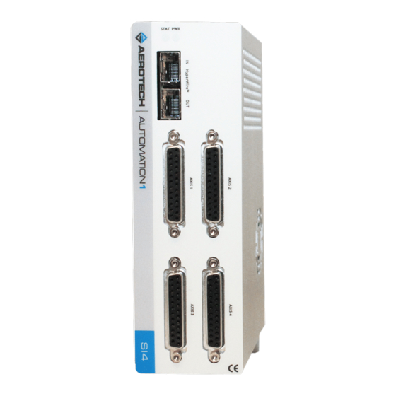
Chapter 1: SI4 Overview The SI4 is a multi-axis digital drive based on the HyperWire communication protocol. The drive provides deterministic behavior, auto-identification, and is fully software configurable. The drive controls amplifiers which accept clock-and-direction commands. Figure 1-1: SI4 Stepper Controller www.aerotech.com... -
Page 14: Figure 1-2: Si4-Oem Stepper Controller
Hardware Manual Figure 1-2: SI4-OEM Stepper Controller www.aerotech.com... -
Page 15: Table 1-1: Feature Summary
Two Axes of Control, OEM Packaging -4P1 Four Axes of Control, Standard Packaging -4P2 Four Axes of Control, OEM Packaging Encoder (Section 2.2.5.2.) No Absolute Encoder support Absolute Encoder support Version -DEFAULT Firmware Matches Software Line -LEGACY Legacy Firmware Version X.XX.XXX www.aerotech.com... -
Page 16: Figure 1-3: Functional Diagram
Hardware Manual The block diagram that follows shows a summary of the connector signals. Figure 1-3: Functional Diagram www.aerotech.com... -
Page 17: Electrical Specifications
Description Input Voltage 24 VDC 2-Axis: 2 A max, 0.45 A typical Control Supply Input Current 4-Axis: 2 A max, 0.6 A typical User Power Supply Output 5 VDC (@ 500 mA) Modes of Operation Stepper Protective Features Control power supply under voltage www.aerotech.com... -
Page 18: Mechanical Specifications
Section 1.2.2. Dimensions Refer to Airflow ~25 mm Minimum Clearance Connectors ~100 mm Standard Provided by internal fan Minimum Airflow (over the drive) 4.2 CMF (NOTE: Customer Supplied) Section 1.3. Environmental Specifications Operating Temperature Refer to Drive IP Rating IP20 www.aerotech.com... -
Page 19: Dimensions
Hardware Manual 1.2.2. Dimensions Figure 1-4: Dimensions [-2P1 (Standard 2-Axis)] www.aerotech.com... -
Page 20: Figure 1-5: Dimensions [-4P1 (Standard 4-Axis)]
Hardware Manual Figure 1-5: Dimensions [-4P1 (Standard 4-Axis)] www.aerotech.com... -
Page 21: Figure 1-6: Dimensions [-2P2 (Oem 2-Axis)]
Hardware Manual Figure 1-6: Dimensions [-2P2 (OEM 2-Axis)] www.aerotech.com... -
Page 22: Figure 1-7: Dimensions [-4P2 (Oem 4-Axis)]
Hardware Manual Figure 1-7: Dimensions [-4P2 (OEM 4-Axis)] www.aerotech.com... -
Page 23: Din Rail Mounting
3. Secure the DIN Rail to the mounting surface with #10-32 screws spaced every six inches. NOTE: Do not install the DIN rail to the mounting surface with the components already attached. 4. Install all components on to the DIN rail. Table 1-4: Mounting Parts Aerotech P/N DIN Rail EAM00914 DIN Rail Clip Kit HyperWire-DIN... -
Page 24: Oem Mounting
2. Attach the drive to the standoffs with the M3 screws. These screws are included with the drive. Table 1-5: OEM Mounting Parts Aerotech P/N M3 Threaded Hex Standoff, 10 mm length EIH01181 M3 Philips Pan Head Screw, 8 mm length HCY0003008 www.aerotech.com... -
Page 25: Environmental Specifications
0 m to 2,000 m (0 ft to 6,562 ft) above sea level. Operating Altitude If you must operate this product above 2,000 m or below sea level, contact Aerotech, Inc. Pollution Degree 2 Pollution Typically only nonconductive pollution occurs. - Page 26 Hardware Manual This page intentionally left blank. www.aerotech.com...
-
Page 27: Chapter 2: Installation And Configuration
Control Power Common Input Protective Ground Table 2-2: Control Supply Mating Connector Ratings Specification Description Type 3-Pin Terminal Block Aerotech: ECK02456 Part Numbers Phoenix: 1839610 One conductor, stranded with ferrule 18...22 AWG (0.25...0.75 mm and plastic sleeve Conductor Cross Two conductors (same cross-... -
Page 28: Minimizing Noise For Emc/Ce Compliance
2. Mount drives and power supplies on a conductive panel.Keep wire-run lengths to a minimum. 3. Use a separate wire for each ground connection to the drive.Use the shortest possible wire length. Section 2.5. System For additional SI4 system interconnection information, refer to Interconnection www.aerotech.com... -
Page 29: Axis Connector
Bidirectional Absolute Clock - Output Table 2-4: Axis Mating Connector Ratings Specification 25-Pin Solder Cup Backshell Aerotech Part Number ECK00101 ECK00656 Amphenol Part Number DB25P064TXLF 17E-1726-2 Maximum Wire Size 20 AWG (0.5 mm (1) Refer to the manufacturer website for additional information. -
Page 30: Stepper Clock And Stepper Direction Signals
Reverse the A and A-N or B and B-N wires at the stepper motor driver. Table 2-7: Stepper Direction Signal Output Polarity Specification Value Negative / CCW Direction Logic Low (0 V) Positive / CW Direction Logic High (+5 V) Figure 2-2: Stepper Clock and Stepper Direction Timing www.aerotech.com... -
Page 31: Figure 2-3: Stepper Clock And Stepper Direction Output Schematic
Hardware Manual Figure 2-3: Stepper Clock and Stepper Direction Output Schematic www.aerotech.com... -
Page 32: End Of Travel Limits
Use NPN-type normally-closed limit switches (Active High) to provide fail-safe behavior in the event of an open circuit. Figure 2-4: End of Travel Limit Input Connections Figure 2-5: End of Travel Limit Input Schematic www.aerotech.com... -
Page 33: End Of Travel Limit Phasing
To correct this, swap the connections to the CW and CCW inputs at the Feedback connector or swap the CW and CCW limit functionality in the software using the EndOfTravelLimitSetup parameter. View the logic level of the EOT limit inputs in the Diagnostics display (shown in Figure 2-6). Figure 2-6: End of Travel Limit Input Diagnostic Display www.aerotech.com... -
Page 34: Amplifier Fault Inputs
Use the amplifier fault input to monitor the stepper driver status. Use the FaultSetup parameter to configure the active polarity. The use of this input is optional. Table 2-9: Amplifier Fault Input Specifications Specification Value Maximum Input Voltage Figure 2-7: Fault Input Schematic www.aerotech.com... -
Page 35: Amplifier Enable Output
Amplifier Enable Connector Pin on the Axis Connector Pin # Description In/Out/Bi Amplifier Enable Output Table 2-11: Amplifier Enable Output Specifications Specification Value High-Level Output Voltage 4.4 V Output Current Source / Sink 10 mA Figure 2-8: Amplifier Enable Output Schematic www.aerotech.com... -
Page 36: Primary Encoder Inputs
Primary Cosine + Input Primary Marker + Input Absolute Data + Bidirectional Absolute Clock + Output Signal Common Output Primary Sine - Input Primary Cosine - Input Primary Marker - Input Absolute Data - Bidirectional Absolute Clock - Output www.aerotech.com... -
Page 37: Square Wave Encoder
Use twisted-pair wiring for the highest performance and noise immunity. Table 2-13: Square Wave Encoder Specifications Specification Value Encoder Frequency 10 MHz maximum (25 ns minimum edge separation) x4 Quadrature Decoding 40 million counts/sec Figure 2-9: Square Wave Encoder Schematic (Axis Connector) www.aerotech.com... -
Page 38: Absolute Encoder
Use twisted-pair wiring for the highest performance and noise immunity. Refer to Figure 2-10 for the serial data stream interface. Refer to the Help file for information on how to set up your EnDat or BiSS absolute encoder parameters. Figure 2-10: Absolute Encoder Schematic (Axis Connector) www.aerotech.com... -
Page 39: Encoder Phasing
Figure 2-11: Encoder Phasing Reference Diagram (Standard) IMPORTANT: Encoder manufacturers may refer to the encoder signals as A, B, and Z. The proper phase relationship between signals is shown in Figure 2-11. Figure 2-12: Position Feedback in the Diagnostic Display www.aerotech.com... -
Page 40: Stepper Motor Phasing
After the motor has been phased, if you want to change the direction of positive motion, use the ReverseMotionDirection parameter. Figure 2-13: Positive Motor Direction For Aerotech-supplied systems, the motor and encoder are correctly configured and connection adjustments are not necessary. www.aerotech.com... -
Page 41: Digital I/O Connector
Output +5 V Output Table 2-15: Digital I/O Mating Connector Ratings [-EB1] Specification 26-Pin Solder Cup Backshell Aerotech Part Number ECK02514 ECK02517 3M Part Number 10126-3000PE 10326-52F0-008 Maximum Wire Size 24 AWG (0.2 mm (1) Refer to the manufacturer website for additional information. -
Page 42: Digital Outputs
Opto-Isolated Digital Output 1 Output Opto-Isolated Digital Output 2 Output Opto-Isolated Digital Output 3 Output Output Common for Digital Outputs 4-7 Output Opto-Isolated Digital Output 4 Output Opto-Isolated Digital Output 5 Output Opto-Isolated Digital Output 6 Output Opto-Isolated Digital Output 7 Output www.aerotech.com... -
Page 43: Figure 2-14: Digital Outputs Schematic
Hardware Manual Figure 2-14: Digital Outputs Schematic www.aerotech.com... -
Page 44: Figure 2-15: Digital Outputs Connected In Current Sourcing Mode
Hardware Manual Figure 2-15: Digital Outputs Connected in Current Sourcing Mode Figure 2-16: Digital Outputs Connected in Current Sinking Mode www.aerotech.com... -
Page 45: Digital Inputs
Opto-Isolated Digital Input 2 Input Opto-Isolated Digital Input 3 Input Input Common for Digital Inputs 4-7 Output Opto-Isolated Digital Input 4 Input Opto-Isolated Digital Input 5 Input Opto-Isolated Digital Input 6 Input Opto-Isolated Digital Input 7 Input Figure 2-17: Digital Inputs Schematic www.aerotech.com... -
Page 46: Figure 2-18: Digital Inputs Connected To Current Sourcing (Pnp) Devices
Hardware Manual Each group of four inputs must be connected in an all sourcing or all sinking configuration. Figure 2-18: Digital Inputs Connected to Current Sourcing (PNP) Devices Figure 2-19: Digital Inputs Connected to Current Sinking (NPN) Devices www.aerotech.com... -
Page 47: High-Speed User Input
5V - 24 V input voltages Input Current 10 mA Input Device HCPL-0630 Delay 50 nsec Table 2-21: High-Speed Input Pins on the Digital I/O Connector Pin # Description In/Out/Bi High-Speed Differential Input 8- Input High-Speed Differential Input 8+ Input Figure 2-20: High-Speed Input www.aerotech.com... -
Page 48: Hyperwire Interface
HyperWire Cable Part Numbers Part Number Description HYPERWIRE-AO10-5 HyperWire cable, active optical, 0.5 m HYPERWIRE-AO10-10 HyperWire cable, active optical, 1.0 m HYPERWIRE-AO10-30 HyperWire cable, active optical, 3.0 m HYPERWIRE-AO10-50 HyperWire cable, active optical, 5.0 m HYPERWIRE-AO10-200 HyperWire cable, active optical, 20.0 m www.aerotech.com... -
Page 49: System Interconnection
Hardware Manual 2.5. System Interconnection Figure 2-21: System Interconnection Drawing (Best Practice) www.aerotech.com... -
Page 50: Pc Configuration And Operation Information
Hardware Manual 2.6. PC Configuration and Operation Information For more information about hardware requirements, PC configuration, programming, system operation, and utilities, refer to the Help file. www.aerotech.com... -
Page 51: Chapter 3: Maintenance
The light is configured to blink for setup. Table 2-25: Troubleshooting Symptom Possible Cause and Solution Make sure the power LED is illuminated (this indicates that power is present). No Communication Make sure that all communication cables (HyperWire, for example) are fully inserted in their ports. www.aerotech.com... -
Page 52: Preventative Maintenance
Also make sure that it does not go onto the outer connectors and components. Internal contamination from the cleaning solution can cause corrosion and electrical short circuits. Do not clean the labels with a cleaning solution because it might remove the label information. www.aerotech.com... -
Page 53: Appendix A: Warranty And Field Service
All Other Repairs - After Aerotech's evaluation, the buyer shall be notified of the repair cost. At such time the buyer must issue a valid purchase order to cover the cost of the repair and freight, or authorize the product(s) to be shipped back as is, at the buyer's expense. - Page 54 Aerotech's approval. On-site Warranty Repair If an Aerotech product cannot be made functional by telephone assistance or by sending and having the customer install replacement parts, and cannot be returned to the Aerotech service center for...
-
Page 55: Appendix B: Revision History
General Updates / Organization 1.04 Updates to EU Declaration of Conformity 1.03 General Updates Updates were made to: Figure 1-3 1.02 Table 1-2 Section 1.2.3. DIN Rail Mounting Section 2.3.3. High-Speed User Input 1.01 Added OEM configuration 1.00 New Manual www.aerotech.com... - Page 56 Hardware Manual This page intentionally left blank. www.aerotech.com...
-
Page 57: Index
Check for fluids or electrically conductive material Drawing number exposure Drive and Software Compatibility Cleaning Drive IP Rating Clock and Direction Output Schematic IP20 Clock and Direction Timing Clock Output Signals Conducted and Radiated Emissions EAM00914 (DIN Rail Part Number) connections, examining www.aerotech.com... - Page 58 End of Travel Limit Input Diagnostic Display Mounting Orientation End of Travel Limit Input Schematic High-Speed Input Outputs Connected in Current Sinking Mode OEM Mounting Procedure Outputs Connected in Current Sourcing Mode Operation Square Wave Encoder Schematic (Axis Connector) www.aerotech.com...
- Page 59 Revision History RS-422 Encoder Specifications (Axis Connector) RS-422 Line Driver Encoder Warranty and Field Service Safety Procedures and Warnings serial data stream serial number Specifications Amplifier Enable Output Amplifier Fault Input Control Supply Connector Wiring Digital Inputs Digital Outputs www.aerotech.com...
- Page 60 Index SI4 Hardware Manual This page intentionally left blank. www.aerotech.com...
Need help?
Do you have a question about the Automation1 SI4-2P1 and is the answer not in the manual?
Questions and answers