Table of Contents
Advertisement
Quick Links
Advertisement
Table of Contents

Subscribe to Our Youtube Channel
Related Manuals for Aerotech Automation1 GI4 Galvo


Summary of Contents for Aerotech Automation1 GI4 Galvo
-
Page 1: Automation1 Gi4 Galvo Scanner Controller
Automation1 GI4 Galvo Scanner Controller HARDWARE MANUAL Revision 1.00... - Page 2 Global Technical Support Portal for information and support about your Aerotech, Inc. products. The website supplies software, product manuals, Help files, training schedules, and PC-to-PC remote technical support. If necessary, you can complete Product Return (RMA) forms and get information about repairs and spare or replacement parts.
-
Page 3: Table Of Contents
GI4 Hardware Manual Table of Contents Table of Contents Automation1 GI4 Galvo Scanner Controller Table of Contents List of Figures List of Tables EU Declaration of Conformity Safety Procedures and Warnings Installation Overview Chapter 1: Introduction 1.1. Electrical Specifications 1.2. Mechanical Specifications 1.2.1. -
Page 4: List Of Figures
Digital Inputs Connected to Current Sinking (NPN) Devices Figure 2-9: High-Speed Input Figure 2-10: TTL Output Figure 2-11: PSO TTL Outputs Schematic Figure 2-12: PSO External Sync Input Schematic Figure 2-13: Analog Outputs Schematic Figure 2-14: Analog Inputs Schematic Figure 2-15: System Interconnection Drawing (Best Practice) www.aerotech.com... -
Page 5: List Of Tables
Table 2-27: Analog Input Pins on the Analog I/O and Laser Interface Connector Table 2-28: Sync Port Cables Table 2-29: HyperWire Card Part Number Table 2-30: HyperWire Cable Part Numbers Table 3-1: LED Description Table 3-2: Troubleshooting Table 3-3: Preventative Maintenance www.aerotech.com... - Page 6 List of Tables GI4 Hardware Manual This page intentionally left blank. www.aerotech.com...
-
Page 7: Eu Declaration Of Conformity
GI4 Hardware Manual EU Declaration of Conformity EU Declaration of Conformity Manufacturer Aerotech, Inc. Address 101 Zeta Drive Pittsburgh, PA 15238-2811 Product Model/Types This is to certify that the aforementioned product is in accordance with the applicable requirements of the following directive(s):... - Page 8 EU Declaration of Conformity GI4 Hardware Manual This page intentionally left blank. www.aerotech.com...
-
Page 9: Safety Procedures And Warnings
To find the newest information about this product, refer to www.aerotech.com. If you do not understand the information in this manual, contact Aerotech Global Technical Support. IMPORTANT: This product has been designed for light industrial manufacturing or laboratory environments. - Page 10 Safety Procedures and Warnings GI4 Hardware Manual This page intentionally left blank. www.aerotech.com...
-
Page 11: Installation Overview
Section 2.2. Connect the PC HyperWire to the HyperWire In port. Section 2.6. Connect the laser interface input and additional I/O as required by your Section 2.4. application. Connect the power supply to the Control Supply. Section 2.1.1. Figure 1: Installation Connection Overview (Standard) www.aerotech.com... - Page 12 Section 2.2. Connect the PC HyperWire to the HyperWire In port. Section 2.6. Connect the laser interface input and additional I/O as required by your Section 2.4. application. Connect the power supply to the Control Supply. Section 2.1.1. Figure 2: Installation Connection Overview (OEM) www.aerotech.com...
-
Page 13: Chapter 1: Introduction
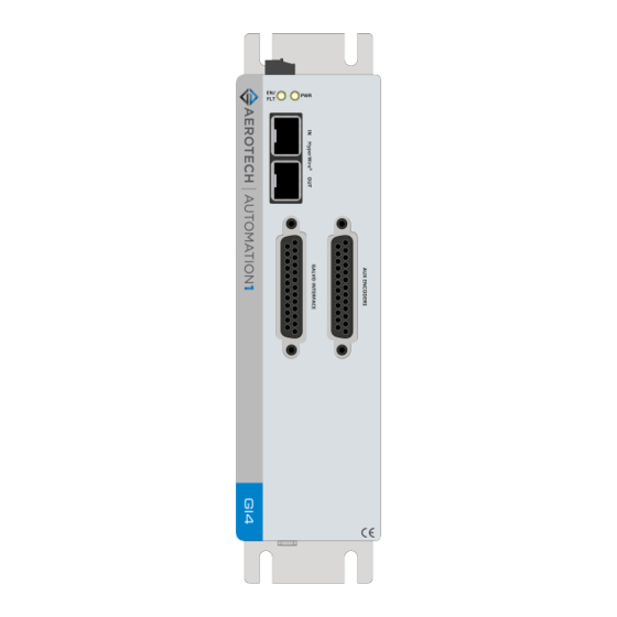
The drive provides open-loop control of galvo scanners. It lets you synchronize galvo and servo motion to mark parts with no limit to size and complexity. Figure 1-1: GI4 Galvo Scanner Controller www.aerotech.com... -
Page 14: Figure 1-2: Gi4-Oem Galvo Scanner Controller
Chapter 1: Introduction GI4 Hardware Manual Figure 1-2: GI4-OEM Galvo Scanner Controller www.aerotech.com... -
Page 15: Table 1-1: Feature Summary
2 or more axes. Three-axis Part-Speed PSO firing, which uses the PSO firing circuit based off of -PSO6 the commanded vector velocity of 3 or more axes. Version -DEFAULT Firmware Matches Software Line -LEGACY Legacy Firmware Version X.XX.XXX www.aerotech.com... -
Page 16: Figure 1-3: Functional Diagram
Chapter 1: Introduction GI4 Hardware Manual The block diagram that follows shows a summary of the connector signals. Figure 1-3: Functional Diagram www.aerotech.com... -
Page 17: Electrical Specifications
Table 1-2: Electrical Specifications Description Input Voltage 24 VDC Control Supply Input Current 2 A max, 0.45 A typical User Power Supply Output 5 VDC (@ 500 mA) Modes of Operation Open loop galvo Protective Features Control power supply under voltage www.aerotech.com... -
Page 18: Mechanical Specifications
Mounting Orientation Vertical (typical) Section 1.2.2. Dimensions Dimensions Refer to Airflow ~25 mm Minimum Clearance Connectors ~100 mm Standard Provided by internal fan Minimum Airflow (over the drive) 4.2 CMF (NOTE: Customer Supplied) Operating Temperature Refer to Section 1.3. Environmental Specifications www.aerotech.com... -
Page 19: Dimensions
GI4 Hardware Manual 1.2.2. Dimensions 1.2.2. Dimensions Figure 1-4: Dimensions [-P1 Package] www.aerotech.com... -
Page 20: Figure 1-5: Dimensions [-P2 Package]
1.2.2. Dimensions GI4 Hardware Manual Figure 1-5: Dimensions [-P2 Package] www.aerotech.com... -
Page 21: Din Rail Mounting
3. Secure the DIN Rail to the mounting surface with #10-32 screws spaced every six inches. NOTE: Do not install the DIN rail to the mounting surface with the components already attached. 4. Install all components on to the DIN rail. Table 1-4: Mounting Parts Aerotech P/N DIN Rail EAM00914 DIN Rail Clip Kit HyperWire-DIN... -
Page 22: Oem Mounting
2. Attach the drive to the standoffs with the M3 screws. These screws are included with the drive. Table 1-5: OEM Mounting Parts Aerotech P/N M3 Threaded Hex Standoff, 10 mm length EIH01181 M3 Philips Pan Head Screw, 8 mm length HCY0003008 www.aerotech.com... -
Page 23: Environmental Specifications
0 m to 2,000 m (0 ft to 6,562 ft) above sea level. Operating Altitude If you must operate this product above 2,000 m or below sea level, contact Aerotech, Inc. Pollution Degree 2 Pollution Typically only nonconductive pollution occurs. -
Page 24: Drive And Software Compatibility
This table shows the available drives and which version of the software first supported each drive. In the Last Software Version column, drives that show a specific version number are not supported after that version. Table 1-7: Drive and Software Compatibility Drive Type First Software Version Last Software Version 2.1.0 Current www.aerotech.com... -
Page 25: Chapter 2: Installation And Configuration
Additional information about the system is provided on the Serial and Power labels that are placed on the chassis. The system serial number label contains important information such as the: Customer order number (please provide this number when requesting product support) Drawing number System part number www.aerotech.com... -
Page 26: Input Power Connections
(2 A max, 0.45 A typical) Control Power Common Input 0.34 mm (#22 AWG) Protective Ground 0.34 mm (#22 AWG) Table 2-2: Mating Connector Part Numbers for the Control Supply Connector Aerotech Third Party Screw Wire Size: Type Torque: N·m [AWG] 3-Pin Terminal Block ECK02456 Phoenix 1839610 0.22 - 0.25... -
Page 27: Minimizing Noise For Emc/Ce Compliance
2. Mount drives and power supplies on a conductive panel.Keep wire-run lengths to a minimum. 3. Use a separate wire for each ground connection to the drive.Use the shortest possible wire length. Section 2.7. System For additional GI4 system interconnection information, refer to Interconnection www.aerotech.com... -
Page 28: Galvo Interface Connector
Signal Common Channel 1- Output Channel 2- Output Status- Input Clock- Output Table 2-4: Mating Connector Part Numbers for the Galvo Interface Connector Mating Connector Aerotech P/N Third Party P/N 25-Pin D-Connector ECK00101 FCI DB25P064TXLF Backshell ECK00656 Amphenol 17E-1726-2 www.aerotech.com... -
Page 29: Aux Encoders Connector
Signal Common Axis Sine 1- Bidirectional Axis Cosine 1- Bidirectional Reserved Reserved Table 2-6: Mating Connector Part Numbers for the Aux Encoders Connector Mating Connector Aerotech P/N Third Party P/N 25-Pin D-Connector ECK00101 FCI DB25P064TXLF Backshell ECK00656 Amphenol 17E-1726-2 www.aerotech.com... -
Page 30: Square Wave Encoder
In/Out/Bi Axis Sine 2+ Bidirectional Axis Cosine 2+ Bidirectional Axis Sine 1+ Bidirectional Axis Cosine 1+ Bidirectional Axis Sine 2- Bidirectional Axis Cosine 2- Bidirectional Axis Sine 1- Bidirectional Axis Cosine 1- Bidirectional Figure 2-2: Square Wave Encoder Interface www.aerotech.com... -
Page 31: Digital I/O Connector
High-Speed Differential Input 8- Input High-Speed Differential Input 8+ Input Reserved Common Common +5 V Table 2-10: Mating Connector Part Numbers for the Digital I/O Connector Mating Connector Aerotech P/N Third Party P/N 26-Pin Connector ECK02514 10126-3000PE Backshell ECK02517 10326-52F0-008 www.aerotech.com... -
Page 32: Digital Outputs
Opto-Isolated Digital Output 1 Output Opto-Isolated Digital Output 2 Output Opto-Isolated Digital Output 3 Output Output Common for Digital Outputs 4-7 Opto-Isolated Digital Output 4 Output Opto-Isolated Digital Output 5 Output Opto-Isolated Digital Output 6 Output Opto-Isolated Digital Output 7 Output www.aerotech.com... -
Page 33: Figure 2-3: Digital Outputs Schematic
GI4 Hardware Manual 2.4.1. Digital Outputs Figure 2-3: Digital Outputs Schematic www.aerotech.com... -
Page 34: Figure 2-4: Digital Outputs Connected In Current Sourcing Mode
2.4.1. Digital Outputs GI4 Hardware Manual Figure 2-4: Digital Outputs Connected in Current Sourcing Mode Figure 2-5: Digital Outputs Connected in Current Sinking Mode www.aerotech.com... -
Page 35: Digital Inputs
Opto-Isolated Digital Input 2 Input Opto-Isolated Digital Input 3 Input Input Common for Digital Inputs 4-7 Opto-Isolated Digital Input 4 Input Opto-Isolated Digital Input 5 Input Opto-Isolated Digital Input 6 Input Opto-Isolated Digital Input 7 Input Figure 2-6: Digital Inputs Schematic www.aerotech.com... -
Page 36: Figure 2-7: Digital Inputs Connected To Current Sourcing (Pnp) Devices
GI4 Hardware Manual Each group of four inputs must be connected in an all sourcing or all sinking configuration. Figure 2-7: Digital Inputs Connected to Current Sourcing (PNP) Devices Figure 2-8: Digital Inputs Connected to Current Sinking (NPN) Devices www.aerotech.com... -
Page 37: High-Speed User Input
5V - 24 V input voltages Input Current 10 mA Input Device HCPL-0630 Delay 50 nsec Table 2-16: High-Speed Input Pins on the Digital I/O Connector Pin # Description In/Out/Bi High-Speed Differential Input 8- Input High-Speed Differential Input 8+ Input Figure 2-9: High-Speed Input www.aerotech.com... -
Page 38: Analog I/O And Laser Interface Connector
Input Analog Input 3- (Differential) Input (1) Refer to Section 2.5.2. for more information. Table 2-18: Mating Connector Part Numbers for the Laser Interface Connector Mating Connector Aerotech P/N Third Party P/N 20-Pin Connector ECK02515 10120-3000PE Backshell ECK02518 10320-52F0-008 www.aerotech.com... -
Page 39: Laser Interface Outputs
In/Out/Bi Laser Output 1 / PSO Output (TTL) Output Common Laser Output 2 Output Common Laser Output 3 Output Common Table 2-20: Laser Output Specifications Specification Value Output 5 V, 50 mA (max) Maximum Frequency 12.5 MHz Output Latency 5 ns Figure 2-10: TTL Output www.aerotech.com... -
Page 40: Position Synchronized Output (Pso) Interface
25 MHz Maximum On Time 20 ns Minimum Table 2-23: PSO Output Pins on the Analog I/O and Laser Interface Connector Pin # Description In/Out/Bi Laser Output 1 / PSO Output (TTL) Output Common PSO External Sync Input Figure 2-11: PSO TTL Outputs Schematic www.aerotech.com... -
Page 41: Figure 2-12: Pso External Sync Input Schematic
GI4 Hardware Manual 2.5.2. Position Synchronized Output (PSO) Interface Figure 2-12: PSO External Sync Input Schematic www.aerotech.com... -
Page 42: Analog Outputs
5 mA Resolution (bits) 16 bits Table 2-25: Analog Output Pins on the Analog I/O and Laser Interface Connector Pin # Description In/Out/Bi Analog Output 0 Output Analog Common Analog Output 1 Output Analog Common Figure 2-13: Analog Outputs Schematic www.aerotech.com... -
Page 43: Analog Inputs (Differential)
Analog Input 0- (Differential) Input Analog Input 1+ (Differential) Input Analog Input 1- (Differential) Input Analog Input 2+ (Differential) Input Analog Input 2- (Differential) Input Analog Input 3+ (Differential) Input Analog Input 3- (Differential) Input Figure 2-14: Analog Inputs Schematic www.aerotech.com... -
Page 44: Sync Port
Length 3 dm; Connectors: USB Type A to USB Type A CBL-SYNC-5 Length 5 dm; Connectors: USB Type A to USB Type A CBL-SYNC-7 Length 7 dm; Connectors: USB Type A to USB Type A CBL-SYNC-10 Length 10 dm; Connectors: USB Type A to USB Type A www.aerotech.com... -
Page 45: Hyperwire Interface
HyperWire Cable Part Numbers Part Number Description HYPERWIRE-AO10-5 HyperWire cable, active optical, 0.5 m HYPERWIRE-AO10-10 HyperWire cable, active optical, 1.0 m HYPERWIRE-AO10-30 HyperWire cable, active optical, 3.0 m HYPERWIRE-AO10-50 HyperWire cable, active optical, 5.0 m HYPERWIRE-AO10-200 HyperWire cable, active optical, 20.0 m www.aerotech.com... -
Page 46: System Interconnection
2.7. System Interconnection GI4 Hardware Manual 2.7. System Interconnection Figure 2-15: System Interconnection Drawing (Best Practice) www.aerotech.com... -
Page 47: Pc Configuration And Operation Information
GI4 Hardware Manual 2.8. PC Configuration and Operation Information 2.8. PC Configuration and Operation Information For more information about hardware requirements, PC configuration, programming, system operation, and utilities, refer to the Help file. www.aerotech.com... - Page 48 2.8. PC Configuration and Operation Information GI4 Hardware Manual This page intentionally left blank. www.aerotech.com...
-
Page 49: Chapter 3: Maintenance
The light is configured to blink for setup. Table 3-2: Troubleshooting Symptom Possible Cause and Solution Make sure the power LED is illuminated (this indicates that power is present). No Communication Make sure that all communication cables (HyperWire, for example) are fully inserted in their ports. www.aerotech.com... -
Page 50: Preventative Maintenance
Also make sure that it does not go onto the outer connectors and components. Internal contamination from the cleaning solution can cause corrosion and electrical short circuits. Do not clean the labels with a cleaning solution because it might remove the label information. www.aerotech.com... -
Page 51: Appendix A: Warranty And Field Service
All Other Repairs - After Aerotech's evaluation, the buyer shall be notified of the repair cost. At such time the buyer must issue a valid purchase order to cover the cost of the repair and freight, or authorize the product(s) to be shipped back as is, at the buyer's expense. - Page 52 Aerotech's approval. On-site Warranty Repair If an Aerotech product cannot be made functional by telephone assistance or by sending and having the customer install replacement parts, and cannot be returned to the Aerotech service center for...
-
Page 53: Appendix B: Revision History
GI4 Hardware Manual Appendix B: Revision History Appendix B: Revision History Revision Description 1.00 New Manual www.aerotech.com... - Page 54 Appendix B: Revision History GI4 Hardware Manual This page intentionally left blank. www.aerotech.com...
-
Page 55: Index
EAM00914 (DIN Rail Part Number) Control Supply Connections Electrical Specifications Control Supply Connector EMC/CE Compliance Mating Connector Part Numbers Enclosure Wiring Specifications Environmental Specifications Control Supply specifications EU 2015/863 cooling vents, inspecting examining parts Customer order number cables connections www.aerotech.com... - Page 56 Mating Connector Part Numbers Mounting Orientation High-Speed Input OEM Mounting Procedure High-Speed Input Pins on the Digital I/O Connector Operation High-Speed Input Specifications Overview High-Speed User Input Humidity HyperWire packing list Cable Part Numbers PC Configuration and Operation Information Card Part Number www.aerotech.com...
- Page 57 Specifications Analog Input (Digital / Analog I/O B Connector) Analog Output (Digital and Analog I/O Connector) Control Supply Connector Wiring Digital Inputs Digital Outputs High-Speed Input Laser Outputs RS-422 Encoder (Feedback Connector) Square Wave Encoder (Feedback Connector) www.aerotech.com...
- Page 58 Index GI4 Hardware Manual This page intentionally left blank. www.aerotech.com...
Need help?
Do you have a question about the Automation1 GI4 Galvo and is the answer not in the manual?
Questions and answers