Table of Contents
Advertisement
Quick Links
Advertisement
Table of Contents

Related Manuals for Aerotech Automation1 XL4s


Summary of Contents for Aerotech Automation1 XL4s
-
Page 1: Xl4S Hardware Manual
XL4s HARDWARE MANUAL Revision: 1.04.00... - Page 2 This manual contains proprietary information and may not be reproduced, disclosed, or used in whole or in part without the express written permission of Aerotech, Inc. Product names mentioned herein are used for identification purposes only and may be trademarks of their respective companies.
-
Page 3: Table Of Contents
2.7.1. Emergency Stop Sense Input 2.8. Laser Output Polarity Switch 2.9. Sync Port 2.10. PC Configuration and Operation Information Chapter 3: Maintenance 3.1. Preventative Maintenance 3.2. Board Assembly Appendix A: Warranty and Field Service Appendix B: Revision History Index www.aerotech.com... -
Page 4: List Of Figures
Figure 2-11: Analog Outputs Schematic Figure 2-12: Analog Inputs Schematic Figure 2-13: Encoder Input Connector Encoder Connections Figure 2-14: ESTOP Sense Input Schematic Figure 2-15: Laser Output Polarity Switch Location Figure 3-1: Control Board Assembly Figure 3-2: Power Board Assembly www.aerotech.com... -
Page 5: List Of Tables
Table 2-32: ESTOP Pins on the Encoder Input Connector Table 2-33: Electrical Noise Suppression Devices Table 2-34: Sync-Related Commands Table 2-35: Sync Port Cables Table 3-1: Preventative Maintenance Table 3-2: Control Board Fuse Specifications Table 3-3: Power Board Fuse Specifications www.aerotech.com... - Page 6 List of Tables XL4s Hardware Manual This page intentionally left blank. www.aerotech.com...
-
Page 7: Eu Declaration Of Conformity
XL4s Hardware Manual EU Declaration of Conformity EU Declaration of Conformity Manufacturer Aerotech, Inc. Address 101 Zeta Drive Pittsburgh, PA 15238-2811 Product XL4s Model/Types This is to certify that the aforementioned product is in accordance with the applicable requirements of the... - Page 8 EU Declaration of Conformity XL4s Hardware Manual This page intentionally left blank. www.aerotech.com...
-
Page 9: Agency Approvals
U8 16 04 68995 018 Standards: CAN/CSA-C22.2 No. 61010-1:2012; EN 61010-1:2010; UL 61010-1:2012 Visit https://www.tuev-sued.de/product-testing/certificates to view Aerotech's TÜV SÜD certificates. Type the certificate number listed above in the search bar or type "Aerotech" for a list of all Aerotech certificates. www.aerotech.com... - Page 10 Agency Approvals XL4s Hardware Manual This page intentionally left blank. www.aerotech.com...
-
Page 11: Safety Procedures And Warnings
NOTE: All specifications and illustrations are for reference only and were complete and accurate as of the release of this manual. To find the newest information about this product, refer to www.aerotech.com. DANGER: The voltage from this product can kill you. To decrease the risk of electrical shock, injury, and death, you must obey the precautions that follow. - Page 12 Safety Procedures and Warnings XL4s Hardware Manual This page intentionally left blank. www.aerotech.com...
-
Page 13: Quick Installation Guide
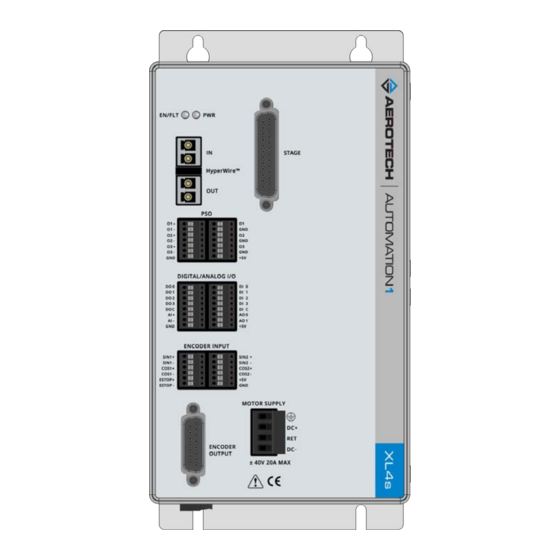
Digital / Analog I/O Section 2.6. Digital and Analog I/O Connectors Motor and Feedback Section 2.5. Stage Motor and Feedback Connector Connections Control Supply Section 2.1.1. Control Supply Connector Motor Supply Section 2.1.2. Motor Supply Connector Figure 1: Quick Start Connections www.aerotech.com... - Page 14 Quick Installation Guide XL4s Hardware Manual This page intentionally left blank. www.aerotech.com...
-
Page 15: Chapter 1: Introduction
Section 2.6.1. Four optically-isolated digital inputs; 5-24V Section 2.6.2. Two 16-bit single-ended analog outputs; ±10 V Section 2.6.3. One 16-bit differential analog input; ±10 V Section 2.6.4. Dedicated 5-24V Emergency Stop sense input Section 2.7.1. Two Sync ports Section 2.9. www.aerotech.com... -
Page 16: Figure 1-2: Functional Diagram
Chapter 1: Introduction XL4s Hardware Manual The block diagram that follows shows a summary of the connector signals. Figure 1-2: Functional Diagram www.aerotech.com... -
Page 17: Electrical Specifications
Input Frequency 50-60 Hz Control Supply Inrush Current 16 A Input Current 0.35 A (max) Output Voltage 76 V Peak Output Current 20 A Continuous Output Current Minimum Load Resistance 0.5 Ω User Power Supply Output 5 VDC (@ 500 mA) www.aerotech.com... -
Page 18: Mechanical Specifications
IP54 Compliant Weight ~2.9 kg Mounting Hardware M4 [#8] screws (four locations, not included) Mounting Orientation Vertical (typical) Dimensions Refer to Section 1.2.2. Dimensions Airflow ~25 mm Minimum Clearance Connectors ~100 mm Operating Temperature Refer to Section 1.3. Environmental Specifications www.aerotech.com... -
Page 19: Dimensions
XL4s Hardware Manual Chapter 1: Introduction 1.2.2. Dimensions Figure 1-3: Dimensions www.aerotech.com... -
Page 20: Environmental Specifications
0 m to 2,000 m (0 ft to 6,562 ft) above sea level. Operating Altitude If you must operate this product above 2,000 m or below sea level, contact Aerotech, Inc. Pollution Degree 2 Pollution Typically only nonconductive pollution occurs. -
Page 21: Drive And Software Compatibility
This table shows the available drives and which version of the software first supported each drive. In the Last Software Version column, drives that show a specific version number are not supported after that version. Table 1-5: Drive and Software Compatibility Drive Type Firmware Revision First Software Version Last Software Version XL4s 6.04.000 Current www.aerotech.com... - Page 22 Chapter 1: Introduction XL4s Hardware Manual This page intentionally left blank. www.aerotech.com...
-
Page 23: Chapter 2: Installation And Configuration
[#16 AWG] (1)The wire insulation is rated for 300 V. Table 2-2: Mating Connector Part Numbers for the Control Supply Connector Screw Torque Wire Size: Type Aerotech P/N Third Party P/N Value: N·m [AWG] 3-Pin Terminal Block ECK00213 Phoenix 1754465 0.5 - 0.6... -
Page 24: Motor Supply Connector
(#14 AWG) (1)The wire insulation is rated for 300 V. Table 2-4: Mating Connector Part Numbers for the Motor Supply Connector Screw Torque Wire Size: Type Aerotech P/N Third Party P/N Value: N·m [AWG] 4-Pin Terminal Block ECK01581 Phoenix 1757035 0.5 - 0.6... -
Page 25: External Power Supply Options
Chapter 2: Installation and Configuration 2.1.3. External Power Supply Options You must connect the Motor Supply to a bipolar power supply. Aerotech recommends that you use an Aerotech TM3 transformer which can supply power to a maximum of four controllers. Refer to Figure 2-3. -
Page 26: Figure 2-4: Third-Party Power Supply Connection
Chapter 2: Installation and Configuration XL4s Hardware Manual Figure 2-4: Third-Party Power Supply Connection www.aerotech.com... -
Page 27: Minimizing Conducted, Radiated, And System Noise For Emc/Ce Compliance
Use a line filter, such as Aerotech’s UFM-ST, on the Control Supply AC inputs. The following additional changes could be required for EMC compliance and are recommended during initial EMC system evaluation. -
Page 28: Hyperwire Interface
HyperWire Cable Part Numbers Part Number Description HYPERWIRE-AO10-5 HyperWire cable, active optical, 0.5 m HYPERWIRE-AO10-10 HyperWire cable, active optical, 1.0 m HYPERWIRE-AO10-30 HyperWire cable, active optical, 3.0 m HYPERWIRE-AO10-50 HyperWire cable, active optical, 5.0 m HYPERWIRE-AO10-200 HyperWire cable, active optical, 20.0 m www.aerotech.com... -
Page 29: Position Synchronized Output Connector
When the PSO generates pulses, minimum latency occurs between the trigger condition and the output. Aerotech recommends that you use an RS-422 line receiver or an opto-isolator if your system: Uses cables with long lengths in work areas where a lot of electrical noise occurs. -
Page 30: Encoder Output Connector
Reserved COS+ Output Reserved Reserved Reserved Ground Table 2-12: Mating Connector Part Numbers for the Encoder Output Connector Mating Connector Aerotech P/N Third Party P/N 15-Pin D-Connector ECK00100 Amphenol DA15P064TXLF Backshell ECK01022 Amphenol 17E-1725-2 Figure 2-5: Encoder Outputs Schematic www.aerotech.com... -
Page 31: Figure 2-6: Pso External Sync Input Schematic
XL4s Hardware Manual Chapter 2: Installation and Configuration Table 2-13: PSO External Sync Specifications Specification Value Voltage 3.3 VDC Frequency 25 MHz Maximum On Time 20 ns Minimum Figure 2-6: PSO External Sync Input Schematic www.aerotech.com... -
Page 32: Stage Motor And Feedback Connector
Encoder Ground Reserved Frame Ground Motor - Output Motor - Output Table 2-15: Mating Connector Part Numbers for the Stage Motor and Feedback Connector Mating Connector Aerotech P/N Third Party P/N 25-Pin D-Connector ECK00101 FCI DB25P064TXLF Backshell ECK00656 Amphenol 17E-1726-2 www.aerotech.com... -
Page 33: Analog Encoder Inputs
Table 2-16: Analog Encoder Input Specifications Specification Value Input Frequency (max) 500 kHz Input Amplitude 0.6 to 1.2 Vpk-pk Interpolation Factor (max) 262,144 Input Common Mode 1.5 to 3.5 VDC (1) Any single-ended encoder signal measured with respect to ground. www.aerotech.com... -
Page 34: Digital And Analog I/O Connectors
Output Analog Output 1 Output Input Table 2-19: Mating Connector Part Numbers for the Digital / Analog I/O Connectors Wire Size: mm [AWG] Mating Connector Aerotech P/N Third Party P/N 8-Pin Terminal Block ECK01386 Phoenix 1881383 0.5 - 0.080 [20-28] www.aerotech.com... -
Page 35: Digital Outputs
Table 2-21: Digital Output Pins on the Digital/Analog I/O A Connector Pin # Label Description In/Out/Bi Digital Output 0 (Optically-Isolated) Output Digital Output 1 (Optically-Isolated) Output Digital Output 2 (Optically-Isolated) Output Digital Output 3 (Optically-Isolated) Output Digital Output Common Input www.aerotech.com... -
Page 36: Figure 2-7: Digital Outputs Connected In Current Sourcing Mode
Chapter 2: Installation and Configuration XL4s Hardware Manual Figure 2-7: Digital Outputs Connected in Current Sourcing Mode Figure 2-8: Digital Outputs Connected in Current Sinking Mode www.aerotech.com... -
Page 37: Digital Inputs
Digital Input 0 (Optically-Isolated) Input Digital Input 1 (Optically-Isolated) Input Digital Input 2 (Optically-Isolated) Input Digital Input 3 (Optically-Isolated) Input Digital Input Common Input Figure 2-9: Digital Inputs Connected to Current Sinking Devices Figure 2-10: Digital Inputs Connected to Current Sourcing Devices www.aerotech.com... -
Page 38: Analog Outputs
Output Current 5 mA Resolution (bits) 16 bits Table 2-25: Analog Output Pins on the Digital / Analog I/O B Connector Pin # Label Description In/Out/Bi Analog Output 0 Output Analog Output 1 Output Figure 2-11: Analog Outputs Schematic www.aerotech.com... -
Page 39: Analog Inputs (Differential)
1. Signals outside of this range may damage the input Table 2-27: Analog Input Pins on the Digital / Analog I/O B Connector Pin # Label Description In/Out/Bi Analog Input + Input Analog Input - Input Ground Figure 2-12: Analog Inputs Schematic www.aerotech.com... -
Page 40: Encoder Input Connectors
Reserved COS2- Reserved +5V Encoder Power Output Ground Table 2-31: Mating Connector Part Numbers for the Encoder Input Connector Wire Size: mm [AWG] Type Aerotech P/N Third Party P/N 6-Pin Terminal Block ECK02220 Phoenix 1881367 0.5 - 0.080 [20-28] www.aerotech.com... -
Page 41: Figure 2-13: Encoder Input Connector Encoder Connections
XL4s Hardware Manual Chapter 2: Installation and Configuration Figure 2-13: Encoder Input Connector Encoder Connections www.aerotech.com... -
Page 42: Emergency Stop Sense Input
Refer to Table 2-33 to see the types of devices you can use. Table 2-33: Electrical Noise Suppression Devices Device Aerotech P/N Third Party P/N RC (.1uf / 200 ohm) Network EIC00240 Electrocube RG1782-8 Varistor EID00160 Littelfuse V250LA40A www.aerotech.com... -
Page 43: Laser Output Polarity Switch
XL4s Hardware Manual Chapter 2: Installation and Configuration 2.8. Laser Output Polarity Switch The Laser Output Polarity switches are reserved for future use. Figure 2-15: Laser Output Polarity Switch Location www.aerotech.com... -
Page 44: Sync Port
Length 3 dm; Connectors: USB Type A to USB Type A CBL-SYNC-5 Length 5 dm; Connectors: USB Type A to USB Type A CBL-SYNC-7 Length 7 dm; Connectors: USB Type A to USB Type A CBL-SYNC-10 Length 10 dm; Connectors: USB Type A to USB Type A www.aerotech.com... -
Page 45: Pc Configuration And Operation Information
XL4s Hardware Manual Chapter 2: Installation and Configuration 2.10. PC Configuration and Operation Information For more information about hardware requirements, PC configuration, programming, system operation, and utilities, refer to the Help file. www.aerotech.com... - Page 46 Chapter 2: Installation and Configuration XL4s Hardware Manual This page intentionally left blank. www.aerotech.com...
-
Page 47: Chapter 3: Maintenance
Do not use fluids and sprays to clean the XL4s because they can easily go into the chassis or onto the outer connectors and components. If a cleaning solution goes into the XL4s, internal contamination can cause corrosion and electrical short circuits. Do not clean the labels with a cleaning solution because it might remove the label information. www.aerotech.com... -
Page 48: Board Assembly
DANGER: Before you open the XL4s chassis, you must disconnect the Mains power connection. Figure 3-1: Control Board Assembly Table 3-2: Control Board Fuse Specifications Fuse Description Size Aerotech P/N Third Party P/N Control Supply Power at Pin-1 2 A S.B. EIF01048 Littelfuse 0875002.MXEP Control Supply Power at Pin-1 2 A S.B. -
Page 49: Figure 3-2: Power Board Assembly
DANGER: Before you open the XL4s chassis, you must disconnect the Mains power connection. Figure 3-2: Power Board Assembly Table 3-3: Power Board Fuse Specifications Fuse Description Size Aerotech P/N Third Party P/N Motor Bus Supply 10 A S.B. EF01020 Littelfuse 215010.P Motor Bus Supply 10 A S.B. - Page 50 Chapter 3: Maintenance XL4s Hardware Manual This page intentionally left blank. www.aerotech.com...
-
Page 51: Appendix A: Warranty And Field Service
Aerotech makes no warranty that its products are fit for the use or purpose to which they may be put by the buyer, whether or not such use or purpose has been disclosed to Aerotech in specifications or drawings previously or subsequently provided, or whether or not Aerotech’s... - Page 52 Aerotech's approval. On-site Warranty Repair If an Aerotech product cannot be made functional by telephone assistance or by sending and having the customer install replacement parts, and cannot be returned to the Aerotech service center for repair, and if Aerotech determines the problem could be warranty-related, then the following policy applies:...
-
Page 53: Appendix B: Revision History
XL4s Hardware Manual Appendix B: Revision History Appendix B: Revision History Revision Description 1.04.00 Updated Section 1.2. Mechanical Specifications Updated Table 1-1 1.02.00 Updated to AUTOMATION1 hardware 1.01.00 Added Table 2-13 1.00.00 New Manual www.aerotech.com... - Page 54 Appendix B: Revision History XL4s Hardware Manual This page intentionally left blank. www.aerotech.com...
-
Page 55: Index
Digital Inputs Connected to Current Sinking CAN/CSA-C22.2 No. 61010-1 Devices Check for fluids or electrically conductive Digital Inputs Connected to Current Sourcing material exposure Devices Cleaning Digital Output Pins (Digital/Analog I/O A Connector) Commands Digital Output Specifications Sync www.aerotech.com Index... - Page 56 Third-Party Power Supply Connection 25-26 ESTOP TM3 Transformer Control and Power Wiring 25 ESTOP Pins on the Encoder Input Connector fluids, dangerous ESTOP Sense Input Schematic (Encdoer Input Functional Diagram Connector) EU 2015/863 Global Technical Support examining parts cables Humidity connections Index www.aerotech.com...
- Page 57 Minimum Load Resistance Position Synchronized Output Connector Motor Supply Power Board Assembly Motor Supply Connections Power Board Fuse Specifications Motor Supply Connector Power Supply Options Mating Connector Part Numbers Preventative Maintenance Motor Supply Wiring Specifications PSO Connector Mounting and Cooling www.aerotech.com Index...
- Page 58 Connector) Control Board Fuses Control Supply Connector Wiring Digital Inputs Digital Outputs Encoder Input Connector Motor Supply Wiring Power Board Fuses Unit Weight Stage Motor and Feedback Connector Mating Connector Part Numbers Stage Motor and Feedback Connector Pinout Index www.aerotech.com...
Need help?
Do you have a question about the Automation1 XL4s and is the answer not in the manual?
Questions and answers