Xantrex Truecharge TC1012 Installation Manual
Truecharge 2 series battery charger
Hide thumbs
Also See for Truecharge TC1012:
- Owner's manual (80 pages) ,
- Owner's manual (80 pages) ,
- Installation manual (66 pages)
Table of Contents
Advertisement
Quick Links
Download this manual
See also:
Owner's Manual
Advertisement
Table of Contents

Subscribe to Our Youtube Channel
Related Manuals for Xantrex Truecharge TC1012


Summary of Contents for Xantrex Truecharge TC1012
- Page 1 TC1012 10A–12V TC1512 15A–12V TC2012 20A–12V TC3012 30A–12V TC4012 40A–12V TC5012 50A–12V TC6012 60A–12V TC1524 15A–24V TC2024 20A–24V TC3024 30A–24V TC5024 50A–24V Installation Guide Series Battery Charger This guide for use by qualified installers only...
- Page 3 Truecharge ™ Series Battery Chargers Installation Guide This guide for use by qualified installers only...
-
Page 4: Contact Information
Trademarks Truecharge™ 2 Series Battery Charger is a trademark of Xantrex International. Xantrex is a registered trademark of Xantrex International. Other trademarks, registered trademarks, and product names are the property of their respective owners and are used herein for identification purposes only. -
Page 5: About This Guide
About This Guide Purpose The purpose of this Installation Guide is to provide explanations and procedures for installing and configuring the Truecharge™ 2 Series Battery Charger. Scope The Guide provides safety guidelines, procedures for installing the battery charger, as well as information on configuring the battery charger. - Page 6 When all models are being referred to, they will be referred to as Truecharge™ 2 Battery Chargers. Related Information You can find more information about Xantrex Technology Inc. as well as its products and services at www.xantrex.com 975-0402-01-01 This guide for use by qualified installers only...
-
Page 7: Important Safety Instructions
Important Safety Instructions EAD AND SAVE THIS NSTALLATION UIDE FOR FUTURE REFERENCE This chapter contains important safety, installation, and operating instructions for the Truecharge™ 2 Series Battery Chargers. 1. Before installing and using a Truecharge™ 2 Battery Charger, read all instructions and cautionary markings on a Truecharge™... - Page 8 Charger with damaged or substandard wiring. 5. The use of any attachments not recommended or sold by Xantrex, may result in risk of fire, electric shock, or injury to persons. 6. Do not operate the Truecharge™ 2 Battery Charger if it...
- Page 9 Safety WARNING: Explosion hazard 10. Working in the vicinity of lead-acid batteries is dangerous. Batteries generate explosive gases during normal operation. Therefore, it is of utmost importance that each time before servicing the charger in the vicinity of the battery, that you read this manual and follow the instructions exactly.
- Page 10 Safety 4. If battery acid contacts skin or clothing, wash immediately with soap and water. If acid enters your eye, immediately flood it with running cold water for at least twenty minutes and get medical attention immediately. 5. Never smoke or allow a spark or flame near the engine or batteries.
- Page 11 Safety BATTERY CHARGER LOCATION 15. Locate the Truecharge™ 2 Battery Charger unit away from batteries as practical in a well ventilated compartment. 16. Never place the Truecharge™ 2 Battery Charger unit directly above batteries; gases from a battery will corrode and damage the charger 17.
- Page 12 Safety FCC Information to the User This equipment has been tested and found to comply with the limits for a Class B digital device, pursuant to part 15 of the FCC Rules. These limits are designed to provide reasonable protection against harmful interference in a residential installation.
-
Page 13: Table Of Contents
Contents Important Safety Instructions - - - - - - - - - - - - - - - - - - - - v 1 Introduction Truecharge™ 2 Battery Charger - - - - - - - - - - - - - - - - - - - - - 1–1 Standard and Protection Features - - - - - - - - - - - - - - - - - - - - 1–2 Truecharge™... - Page 14 Contents Installing Optional Accessories- - - - - - - - - - - - - - - - - - - - - -2–24 Mounting the Optional Remote Panel - - - - - - - - - - - - - -2–24 Installing the Optional Battery Temperature Sensor (BTS) 2–25 Configuring the Truecharge™...
-
Page 15: Introduction
Introduction Chapter 1 describes the standard features of a Truecharge™ 2 Battery Charger, as well as its protection features. It also provides information on the different parts of the Truecharge™ 2 Battery Charger including information on the optional remote panel. Truecharge™... -
Page 16: Standard And Protection Features
2.The charger can be programmed with custom charge setpoints using PC interface. This programming can only be done using a special configuration tool operated by Xantrex or a designated OEM. - Page 17 Standard and Protection Features The Truecharge™ 2 Battery Charger provides the following protec- tion features: • reverse polarity protection via an output fuse to guard against reverse battery polarity • AC input out-of-range protection shutdown • ambient over temperature protection shutdown •...
-
Page 18: Truecharge™ 2 Battery Charger
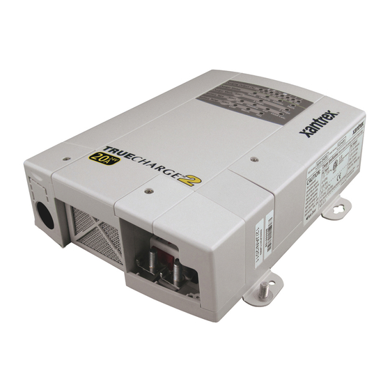
Introduction Truecharge™ 2 Battery Charger This section describes the different parts of the Truecharge™ 2 Battery Charger. Figure 1-1 Truecharge™ 2 Battery Charger Item Description Onboard control and status display panel or simply onboard display (see “Rear Panel” on page 1–6 for more information) for controlling the Truecharge™... - Page 19 Truecharge™ 2 Battery Charger Item Description Fuse access panel cover provides access to the DC fuse in the event of an accidental reverse polarity installation. AC wiring compartment cover provides the installer with easy access to the AC wiring compartment, to allow for a trouble free installation.
-
Page 20: Rear Panel
Introduction Rear Panel This section describes the parts of the rear panel of the Truecharge™ 2 Battery Charger. 40 A model (TC4012) shown. Other models may vary. Figure 1-2 Truecharge™ 2 Battery Charger Rear Panel Item Description BTS port- battery temperature sensor port Communication port - remote panel port Battery positive (+) for bank 3 (6 mm stud) Battery positive (+) for bank 2 (6 mm stud) - Page 21 Rear Panel Item Description Air intake vent - located inside is the fan assembly AC wiring - line, neutral, and ground input wires Important: When installing only a single bank (or one battery) for Truecharge™ 2 Battery Chargers that have multiple outputs, positive bank 1 must be utilized.
-
Page 22: Onboard Control And Status Display Panel
Introduction Onboard Control and Status Display Panel This section describes the parts of the onboard control and status display panel of the Truecharge™ 2 Battery Charger. Important: A “press and hold” action on any panel button means that the button must be held down for more than three seconds then released in order to send the instruction. - Page 23 Onboard Control and Status Display Panel Item Description Charging Output (%) LEDs • The LEDs illuminate like a progress bar displaying the present total output charge current as a percentage of the set maximum charge current. The numbers below the LEDs represent the percentage values.
- Page 24 Introduction Item Description Battery Type Select button Press and hold the button for three seconds to select either of five settings. An indicator LED corresponds to each setting. Each setting maximizes charger performance for its corresponding battery type. • AGM - Absorbent Glass Mat lead-acid battery •...
- Page 25 Onboard Control and Status Display Panel Important: A warning condition notifies the user of an impending problem and will not stop the charger from charging, while a fault condition will stop the charger from charging the battery. Type of fault and warning Charging Output (%) LEDs Charging Output (%) <5...
- Page 26 Introduction Table 1-1 Fault and Warning Indicators Temp Battery Fuse Charger Remote Fault Fault or Warning Condition Low Battery Temp fault (< -25°C) See Figure 1-6. AC input out of range Warning (<104V and >90V) or (<264V and >255V) See Figure 1-5. AC input out of range fault (<90V or >265V)
- Page 27 Onboard Control and Status Display Panel Table 1-1 Fault and Warning Indicators Temp Battery Fuse Charger Remote Fault Fault or Warning Condition Reverse Polarity Fuse fault Internal fault Flashing LED Solid LED Fault LED blinks if current is derated in this region. Imax 0.8 Imax Input...
- Page 28 Introduction Charger Charger ALARM set FAULT set Charger Charger ALARM reset FAULT reset -25 -20 -15 -10 -5 65 70 °C Ambient Temperature derating to 80% Imax. Figure 1-6 Battery and Charger Temperature Thresholds 1–14 975-0402-01-01 This guide for use by qualified installers only...
-
Page 29: Remote Panel (Sold Separately)
Remote Panel (Sold Separately) Remote Panel (Sold Separately) This section describes the parts of the optional remote panel (Part number: 808-8040-00) of the Truecharge™ 2 Battery Charger. The remote panel can be mounted using a communications cable up to 15 m (50 ft) from the Truecharge™... - Page 30 Introduction • Limit the maximum charger output current (20, 40, 60, 80, and 100% of charger rating) to lower the current drawn from the generator or AC source • Set the charger to or on STANDBY • Set or cancel an equalization cycle •...
- Page 31 Remote Panel (Sold Separately) Item Description Charger Status LEDs Displays the present status of the charger. • Ready - a solid light indicates that all batteries are fully charged and in rest stage. • Ready and Charging - solid lights indicate that batteries are fully charged and in float stage.
- Page 32 1–18 This guide for use by qualified installers only...
-
Page 33: Installation
Installation Chapter 2 provides procedures for installing, testing and configuring the Truecharge™ 2 Battery Charger. It covers the following major topics: • “Preparing for Installation” on page 2–2. • “Installing the Truecharge™ 2 Battery Charger” on page 2–12 • “Installing Optional Accessories” on page 2–24 •... -
Page 34: Preparing For Installation
Installation Preparing for Installation WARNING The battery charger must be properly installed with in accordance with all local and application-specific codes and ordinances before it is used. The Truecharge™ 2 Battery Charger is designed to be permanently mounted. Figure 2-1 shows a typical installation with three batteries, a battery temperature sensor (BTS) and a remote panel (both optional). - Page 35 Preparing for Installation AC mains source protected by correct size and type of branch rated circuit breaker AC input wiring compartment DC negative cable DC positive cables DC circuit breakers or DC fused disconnects Battery or battery bank Engine ground bus or DC negative bus Remote panel (optional accessory part number: 808-8040-00) Battery temperature sensor...
-
Page 36: Tools And Materials
Installation Tools and Materials To mount and connect the Truecharge™ 2 Battery Charger you need the following tools: • 10 mm socket wrench and extension for the DC terminals and ground stud • Phillips screwdriver for removing and re-securing the AC and DC wiring compartment covers •... -
Page 37: Location
This battery charger is ignition protected, so it can be installed in areas containing gasoline tanks or fittings which require ignition protected equipment. Xantrex recommends, however, that it is safest not to install electrical equipment in these areas. Close to The Truecharge™... - Page 38 Installation rating means that it meets European and U.S. standards in preventing dripping water from entering the enclosure, and causing shock hazard and damage to equipment. The other possible mounting orientations will not prevent the entry of dripping water, and are not suitable for marine, or a moist environment without the installation of additional drip protection.
- Page 39 Preparing for Installation Deck Mount - this orientation meets IP-32 marine requirements and is drip-proof. Horizontal Wall Mount (with AC wiring higher than DC terminals only) - this orientation meets IP-32 marine requirements and is drip-proof. Vertical Wall Mount (Rear panel facing down or up) - this orientation is allowed in locations that are always dry but is not approved for marine installations without additional drip protection.
-
Page 40: Wiring Requirements
Installation Wiring Requirements WARNING: Shock and fire hazard Wiring and fuse sizes are governed by electrical codes and standards. Different requirements apply in different countries and to different types of installations, for example, boat, home or RV. It is the responsibility of the installer to ensure that each installation complies with all applicable codes and standards. - Page 41 Preparing for Installation Table 2-2 DC Wiring Requirements for 24 V chargers Wire Length Wire Size (AWG and mm max length one way TC1524 TC2024 TC3024 TC5024 feet meters No. 16 No. 14 No. 12 No. 10 1.3 mm 2 mm 3.3 mm 5.3 mm 2.25...
-
Page 42: Ac Wiring
Installation AC Wiring WARNING: Risk of fire Use only on circuits provided with 20A maximum branch circuit protection in accordance with National Electrical Code, NFPA 70. The AC wiring must meet be of sufficient size, and it must be protected by the appropriate size and type of input breaker, based on the jurisdiction and application. -
Page 43: Battery Bank Size Requirements
Preparing for Installation Battery Bank Size Requirements The Truecharge™ 2 Battery Charger is designed to work with a minimum battery bank size. Each bank should meet the minimum Ah rating shown in Table 2-3. Note: If the battery manufacturer has specified the maximum charge current, please follow their recommendation. -
Page 44: Installing The Truecharge™ 2 Battery Charger
Disconnect all sources of AC and DC power before proceeding. Installation Sequence To make charger installation quick and easy, Xantrex recommends that the installation tasks be performed in the following sequence: 1. Select charger mounting position and plan AC and DC cable routing. -
Page 45: Planning Dc Wiring
Installing the Truecharge™ 2 Battery Charger Planning DC Wiring The procedure for installing the DC wiring applies to a single battery, as well as multiple batteries or battery banks. WARNING: Fire or burn hazard To help prevent accidental shorts or sparks, leave the DC disconnects or breakers in the Off position or DC fuses removed from their fuse holders until installation is complete. - Page 46 Installation 4. Install a DC circuit breaker or fused disconnect in each positive cable within 7 inches (17.8 cm) of each battery. Consult your local electrical codes regarding the distance between the battery and the disconnect device. Be sure the breaker or fused disconnect is open. 5.
-
Page 47: Planning Ac Wiring
Installing the Truecharge™ 2 Battery Charger Planning AC Wiring Before connecting AC wiring, make sure the AC source circuit is protected by a breaker switch of the correct size and type, to comply with the electrical code for your location and application. - Page 48 Installation 6. Remove the AC (L, N, ) wires from the AC wiring compartment of the charger. 7. Feed the source AC wire through the included strain relief. Position approximately 1" from end of jacketed portion of the AC wiring. 8.
- Page 49 Installing the Truecharge™ 2 Battery Charger To connect AC wires with the crimp-on butt-splice connector: Important: You must exercise care when crimping butt-splice connectors. Use the crimp tool recommended by the manufacturer for the connector used. a) Using a wire stripper, carefully strip 8 mm (5/16 in.) from the ends of the two wires being connected.
-
Page 50: Mounting The Truecharge™ 2 Battery Charger
Installation Mounting the Truecharge™ 2 Battery Charger Mount the Truecharge™ 2 Battery Charger using all four mounting slots and holes which are provided. For marine only installations, the mounting orientations a) and b) in Figure 2-2 meet the North American and European marine requirements. -
Page 51: Make The Final Connections
Installing the Truecharge™ 2 Battery Charger Make the Final Connections After planning the DC and AC connections and mounting the charger, the last procedures, including installing the DC terminal rubber boots for drip protection, will finalize the wiring connections. NOTE: Not to scale. For illustration purposes only. DC connections Negative Cable (main) to charger. -
Page 52: Installing The Drip Protection Rubber Boots
Installation Installing the Drip Protection Rubber Boots Xantrex recommends that you install the supplied rubber boots over the Truecharge™ 2 Battery Charger DC terminals to provide drip and short circuit protection. To install rubber boots: 1. Before making the DC connections to the charger, feed the rubber boot over the charger end of the DC cables. - Page 53 Installing the Truecharge™ 2 Battery Charger the Truecharge™ 2 Battery Charger (Figure 2-4, item 1). Use a flat washer, a lock washer and a nut (5 included in the installation kit) to secure the connection. Tighten the nuts to 2.3 N-m (20 lb-in.) torque and test that the wire is secure.
-
Page 54: Final Ac Connections
Installation 5. Install the DC chassis ground (earth) from the ground stud on the Truecharge™ 2 Battery Charger to the engine bus or DC ground bus (Figure 2-4, item 15). Use a flat washer, a lock washer and a nut (included in the installation kit) to secure the connection. -
Page 55: Grounding Instructions
Xantrex recommends that you install a DC chassis ground (earth) from the ground stud on the Truecharge™ 2 Battery Charger to the engine bus or DC ground bus. The DC chassis... -
Page 56: Installing Optional Accessories
Installation Installing Optional Accessories Optional accessories are available for purchase at Xantrex. Call Customer Service to order the accessories below: • Remote Panel (Part number: 808-8040-00) • Battery Temperature Sensor (Part number: 808-0232-01) Mounting the Optional Remote Panel To mount the remote panel: 1. -
Page 57: Installing The Optional Battery Temperature Sensor (Bts)
Installing Optional Accessories Installing the Optional Battery Temperature Sensor (BTS) Xantrex strongly recommends that you install the optional Battery Temperature Sensor (BTS) to protect your battery and improve charging accuracy. If no BTS is connected, the charger defaults to the charging temperature settings (Cold, Warm, or Hot). -
Page 58: Configuring The Truecharge™ 2 Battery Charger
Installation Configuring the Truecharge™ 2 Battery Charger Once the charger is connected to a battery on bank 1 or to AC, it is live and it may be configured. The indicator LEDs on the onboard display will illuminate for a second (power on test) before reporting charging and battery status information. -
Page 59: Configuring The Charger Mode
Configuring the Truecharge™ 2 Battery Charger Configuring the Charger Mode Using the Onboard Display Panel To configure the charger mode: Note: By default, the Charger Mode is set to three-stage. 1. Press and hold the Charger Mode Select button for three seconds. - Page 60 Installation Using the Remote Panel To configure the charger mode: Note: By default, the Charger Mode is set to three-stage. 1. Press and hold the Status button for three seconds to enter the Setup mode. Entering the Setup mode will enable you to select the charger mode.
-
Page 61: Configuring The Battery Bank Type
Configuring the Truecharge™ 2 Battery Charger Configuring the Battery Bank Type Using the Onboard Display Panel To configure the battery bank type: Note: By default, the battery type is set to Flooded. 1. Press and hold the Battery Type Select button for three seconds. -
Page 62: Configuring The Battery Temperature Without The Bts - -2-30
Installation Configuring the Battery Temperature without the Using the Onboard Display Panel To configure the battery temperature: Note: By default, the Battery Temp. is set to Warm. 1. Press and hold the Battery Temperature Select button for three seconds. 2. Select the appropriate battery temperature setting. The LEDs will indicate which of the three types is being selected: Warm, Hot, or Cold. -
Page 63: Configuring The Maximum Output Current Percentage
Configuring the Truecharge™ 2 Battery Charger Table 2-4 Battery Temperature Compensation Levels Recommended Temperature for battery Voltage added for temperature Selection temperature of: compensation offset from 25 °C Cold below 5 °C Flooded/PbCa/Gel 0.675 (41 °F) 0.525 Warm between Flooded/PbCa/Gel 5 and 30 °C (41 and 86 °F) above 30 °C... -
Page 64: Installing Batteries
Installation Installing Batteries Replacing old or defective batteries (even installing new batteries) require that you disconnect all AC and DC sources prior to installation. WARNING Battery installation should always be treated like a brand new installation. This means, that all safety and precautionary guidelines that were followed prior and during the installation of the charger, must again be followed in order to avoid risks of electrical shock, injury, or death. -
Page 65: Specifications
Specifications Appendix A contains physical, electrical performance, and regulatory approval specifications for the Truecharge™ 2 Battery Charger. Note: Specifications are subject to change without notice. This guide for use by qualified installers only... -
Page 66: Physical Specifications
Specifications Physical Specifications Base Unit TC1012, TC1512: Dimensions: 200 × 170 × 70mm (7.87 × 6.70 × 2.76 in.) L × W × H TC2012, TC3012, TC4012: 250 × 170 × 70mm (9.84 × 6.70 × 2.76 in.) TC5012, TC6012: 350 ×... -
Page 67: Electrical Specifications
Electrical Specifications Electrical Specifications Number of isolated TC1012: battery bank outputs 1 output TC1512: 2 separated outputs TC2012, TC3012, TC4012, TC5012, TC6012, TC1524, TC2024, TC3024, TC5024: 3 separated outputs Nominal battery voltage 12 V units:12 Vdc 24 V units:24 Vdc Normal operating output 12 V units: 0 –... - Page 68 Specifications Float voltage: 12 V units 24 V units ±0.1 V for 12 V units 25 °C (77 °F) 25 °C (77 °F) ±0.2 V for 24 V units Flooded 13.5 27.0 13.8 27.6 13.4 26.8 Lead-calcium 13.5 27.0 Equalize mode current 50% rated output ±6% Equalize mode—...
-
Page 69: Ac Input Specifications
AC Input Specifications AC Input Specifications AC input voltage range Nominal: 120 Vac, 230 Vac, 240 Vac Full Performance: 105 – 265 Vac ±4 Vac Automatic derating to 80%: 90 – 104 ±4 Vac Maximum AC input current at 104 Vac at 208 Vac TC1012: 2.5 A TC1012: 1.5 A... -
Page 70: Dc Output Specifications
Specifications DC Output Specifications DC output voltage range including 12 V units: 0 – 15.5 Vdc dead battery charging voltage 24 V units: 0 – 31 Vdc Maximum equalization voltage 12 V units: 16 Vdc (no BTS installed) 24 V units: 32 Vdc Voltage accuracy (no load) 12 V units: ±0.1 Vdc at 14.4 Vdc @ 25 °C (77 °F) -
Page 71: Protection Features
Protection Features Protection Features Battery reverse Protected by a replaceable DC output fuse polarity Over-voltage limits The Truecharge™ 2 Battery Charger will stop charging any bank if the output voltage is above 16.6 ±0.5 Vdc. Output current limit TC1012: 10 ±10% A (up to 15.5 V) TC1512: 15 ±10% A (up to 15.5 V) TC2012:... -
Page 72: Approvals
Specifications Approvals Safety NRTL approved to CSA E60335-2-29 and UL1236, including the marine supplement, ignition protection, and UL1564 CE marked, complying with Low Voltage Directive 2006-95-EC, complying with EN60335-2-29 Battery Chargers, including Australian deviations ISO 8846: Ignition Protection for Small Craft ABYC E11 - Alternating Current and Direct Current Electrical Systems on Boats ABYC A31 - Battery Chargers and Inverters... - Page 74 Xantrex Technology Inc. 1 800 670 0707 Tel toll free NA 1 408 987 6030 Tel direct +34 93 470 5330 Europe 1 800 994 7828 Fax toll free NA +34 93 473 6093 Europe customerservice@xantrex.com www.xantrex.com 975-0402-01-01 Printed in China...
Need help?
Do you have a question about the Truecharge TC1012 and is the answer not in the manual?
Questions and answers