
Related Manuals for Xantrex Freedom Marine Series


Summary of Contents for Xantrex Freedom Marine Series
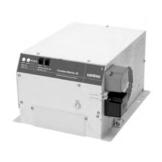
- Page 1 Freedom Marine Owner's Manual Xantrex Freedom Marine Series Inverter/Charger...
- Page 2 Refer all service to qualified personnel. Notice of Copyright Xantrex Freedom Marine Series Inverter/Charger © December 2002 Xantrex International. All rights reserved. Xantrex is a registered trademark of Xantrex International. Disclaimer UNLESS SPECIFICALLY AGREED TO IN WRITING, XANTREX TECHNOLOGY INC. (“XANTREX”) MAKES NO WARRANTY AS TO THE ACCURACY, SUFFICIENCY OR SUITABILITY OF ANY TECHNICAL OR OTHER INFORMATION PROVIDED IN ITS MANUALS OR OTHER DOCUMENTATION.
-
Page 3: Table Of Contents
TABLE OF CONTENTS Introduction......4 Installation Options ....29 Shorepower Configurations Things You Should Know . -
Page 4: Introduction
INTRODUCTION This owner’s manual describes the • The internal transfer switch allows the Freedom Marine Series Inverter/Chargers from Freedom Inverter/Charger to be connected to Xantrex. These units perform four distinct an external AC source and transfer the source functions: power through the unit directly to the loads. - Page 5 INTRODUCTION Multiple Battery Bank Charging Multiple battery bank charging is provided through additional output from the built-in echo- charge. The echo-charge is used to charge start or auxiliary batteries. This Digital echo- charge is current limited to 15 amps and follows the three-stage charge curve of the inverter/charger and battery setting of the house battery bank.
-
Page 6: Things You Should Know
THINGS YOU SHOULD KNOW Circuit Breaker Protection Inverter Idle Circuit The Freedom Inverter/Charger is The idle circuit reduces battery power supplemental circuit breaker protected. The consumption when no AC load is present. INVERT/CHARGE breaker on the front of the Response from idle is instantaneous. When unit protects against sustained inverter/ using a Freedom or Link remote control panel charger over-current conditions. -
Page 7: Power Sharing
THINGS YOU SHOULD KNOW The Power Sharing set point of each unit Electronic Protection has a factory default setting. This can be Fast-acting electronic circuits protect changed when using the Freedom or Link the inverter from overloads and short circuits. remote control panel. -
Page 8: Operation
OPERATION The Freedom Inverter/Charger provides STATUS LEDs 120 volt AC power from auxiliary DC batteries, Each Status LED performs two functions, automatic battery charging and automatic AC providing operation status and battery type transfer switching between an external AC selection. source and inverter mode AC output. - Page 9 OPERATION NOTE: When AC power is available, the when AC power from an external source is connected to the output of the inverter. Inspect default setting for the charger is ON. If the unit wiring for a possible input/output wiring error. was manually turned OFF and AC power is interrupted and becomes available again, the This condition must be corrected before further...
-
Page 10: Echo-Charge
OPERATION When a Freedom or Link remote control panel is connected to the unit, the switch on the unit or on the remote may be used to turn the unit Over-temp ON/OFF. If the unit is turned ON using the front Remote panel switch and then turned OFF using a Battery... -
Page 11: Optional Remote Control Panels
OPTIONAL REMOTE CONTROL PANELS LINK 2000 Remote Control Panel The Link 2000 has the same features as An optional remote control panel is the Link 1000, providing inverter/charger available. The LED bar graphs on the remote control and complete battery state-of-charge control panel show battery voltage and DC information. -
Page 12: Batteries
BATTERIES Wet cell batteries will give off gas as a natural result of charging and will experience some water loss. It is very important that the electrolyte level be checked frequently and topped off with distilled water when necessary. Follow the battery manufacturer’s recommendations for maintenance. -
Page 13: Battery Interconnection
BATTERIES Beware of so-called maintenance-free wet Series Configuration cell batteries. These batteries have calcium Connecting two batteries in series will alloyed with the lead liquid. They are sealed double the voltage of the battery bank. For and water cannot be added. Do not confuse instance, two 6 volt batteries connected in them with true gel cell or AGM batteries—they series will produce 12 volts. -
Page 14: Battery Bank Ratings And Sizing
BATTERIES Parallel Configuration Note: It is not advisable to connect Connecting two batteries in parallel will batteries of different case sizes or amp-hour double the amp-hour rating of the battery bank, ratings in the same battery bank. while the voltage will be the same as each Always use properly sized wire and individual battery. - Page 15 BATTERIES To achieve 50% cycling you should AMP-HOUR CONSUMPTION FORMULAS calculate your amp-hour consumption (AC amps x 10) x 1.1 x hours of between charging cycles and use a battery operation = DC amp hours bank with twice that capacity**. Each AC appliance or tool has a rating plate on it and will (watts/ DC voltage) x 1.1 x hours of be rated in either AC amps or watts or AC VA...
-
Page 16: Battery Charging
BATTERY CHARGING Battery Charging Freedom Battery Chargers Completely charging wet cell deep-cycle Freedom battery chargers are designed batteries requires the battery voltage to be to overcome the limitations of conventional raised beyond what is known as the gassing chargers by utilizing three distinct charge point. - Page 17 BATTERY CHARGING Note: Freedom battery chargers are ON The battery charger stages are: whenever AC power is connected to the Stage 1 - Bulk Charge During the bulk charger input. The charger can be turned OFF charge stage most of the energy that has been using the CHARGE switch on the front of the consumed during discharge is returned to the unit.
- Page 18 BATTERY CHARGING acceptance charge voltage limit. When it Gel cell and Advanced AGM batteries can reaches the float voltage set point, the float accept a higher rate of charge. Consult the charge stage is engaged. manufacturer for specifications. The float charge stage holds the battery Stage 2 - Acceptance Charge The voltage constant at a preset voltage level, acceptance stage immediately follows the bulk...
- Page 19 BATTERY CHARGING The equalizing charge is a timed, eight- WARNINGS hour cycle. The cycle can be ended early by interrupting the AC power to the charger at any time during the cycle. Equalizing should only 1. Do not equalize gel cell batteries. be engaged after the batteries have been fully Check remote default settings.
-
Page 20: Battery Charger Voltage Settings
BATTERY CHARGER VOLTAGE SETTINGS l l e F ° ° * There are two gel battery settings. Check with the battery manufacturer to determine the proper setting for your batteries. Usually, Gel 1 is for long battery life; Gel 2 is for rapid charging. **Default setting when the temperature sensor is not connected. -
Page 21: Installation Precautions
INSTALLATION PRECAUTIONS Before beginning installation, unpack the Before beginning the installation of your inverter/charger, record the serial number on Freedom Marine Inverter/Charger, read the the warranty card. Retain packing materials for owner’s manual. Disconnect all sources of future use. AC and DC power to prevent accidental shock. -
Page 22: Installation
INSTALLATION CAUTION Risk of electrical shock. Do not 5. Do not connect the inverter battery remove cover, no user serviceable parts negative cable to the vessel safety inside. Refer servicing to qualified service ground. Run the negative (-) cable directly to personnel. -
Page 23: Ac Input
INSTALLATION covered in recommended heat shrink tubing. 9. Do not backfeed the AC output of the in- Carefully follow the manufacturer’s directions verter with incoming AC power. A backfeed to meet all requirements. occurs when AC power from shorepower or generator is connected to the output of the 12. -
Page 24: Grounding
INSTALLATION Note: The battery cables are not Grounding connected to the chassis lug of the unit. For safety purposes, the chassis of the Neutral Bonding inverter/charger must be connected to your AC For safety purposes and NEC code ground system. Use 8 AWG bare copper or green insulated wire, strip one end and use a requirements, the Freedom Combi unit screwdriver to secure it to the chassis ground... -
Page 25: Ac Wiring
INSTALLATION rated breakers will be required between the AC Wiring inverter/charger AC output and the loads. Determine which knockout(s) on the front Feed the AC input wire(s) through the or side panels will be utilized and remove them knockout and into the AC wiring compartment. from the inverter. -
Page 26: Ground Fault Circuit Interrupters
INSTALLATION Ground Fault Circult Interrupters DC Wiring To conform to NEC regulations, certain DC wiring is generally very simple—the branch circuits must be equipped with a positive (+, may be red for identification) and Ground Fault Circuit Interrupter (GFCI). negative (-, may be black or yellow for Consult the code or a qualified marine identification) cables from the inverter/charger electrician for details. - Page 27 INSTALLATION • Bolt the positive (+) battery cable with If multiple batteries are used, the 3/8'' ring terminal to the positive (red +) interconnecting jumper cables should be the terminal assembly on the side of the inverter. same AWG as those connected to the Tighten the battery terminal bolts to a torque inverter/charger.
-
Page 28: Battery Cable Fusing
INSTALLATION Battery Cable Fusing For Freedom 10 & 15 A fuse is required by the NEC to protect 200 amp Fuse & Holder PN# 84-4155-00 (C/R)* 200 amp Fuse & Holder PN# 84-4158-00 (R/R)** the battery and cables. A UL Listed DC rated 200 amp Fuse Only PN# 84-4157-00 slow blow fuse must be installed in the positive... -
Page 29: Installation Options
INSTALLATION OPTIONS Installation Options General Guide for Fuse Size and DC Cable Size* Installation options 1, 2, 3, and 4 are the most commonly used applications involving specific i r t shorepower connections, generator power – . t f – . -
Page 30: Dual In/Dual Out Configuration
INSTALLATION OPTIONS Dual In/Dual Out Configuration These diagrams are intended to be a visual representation of the AC power “path” through the Inverter/Charger with AC power applied to 1, 2, or both of the AC input connections. These dia- grams are meant only to show switching characteristics, and they are not intended to illustrate actual circuit components or connections. - Page 31 INSTALLATION OPTIONS Installation Option 1 for Freedom Marine 10, 15, 20, 25, and 30 The inverter is used in a Single Input/Single Output mode. Up to 30 amps is transferred through the Freedom Marine unit with the charger sharing power with all of the AC loads. In this installation example, a single 30 amp shorepower source is available and all AC loads are supplied power through the inverter in charge/transfer mode, or by the inverter in invert mode.
-
Page 32: Installation Option
INSTALLATION OPTIONS Installation Option 2 for Freedom Marine 10, 15, 20, 25, and 30 The inverter is used in a Single Input/Single Output mode. The AC loads are split between main loads and inverter loads. The external sources of AC power can be a single 30 amp shorepower source or a 30 amp breaker from a panel fed by a 50 amp 120 volt single phase (3 wire) shorepower source, 1 leg of a 50 amp 120/240 split phase (4 wire) shorepower source, or a generator. -
Page 33: Installation Option
INSTALLATION OPTIONS Installation Option 3 for Freedom Marine 25 and 30 The inverter is used in a Dual Input/Single Output mode. The AC loads are split between main loads and inverter loads. The external sources of AC power can be two different 30 amp shorepower sources (both neutrals and both “Hots”... - Page 34 INSTALLATION OPTIONS Freedom Marine Installation Option 3 Freedom Marine Model 25, 30 Dual Input/ Single Output 30 Amp Transfer 12 VDC Battery Bank Separate Charge Input Inverter AC Sub Panel Power Sharing Not Active AC ground and DC ground are shown connected, therefore, galvanic protection is Inverter...
- Page 35 INSTALLATION OPTIONS Installation Option 4 for Freedom Marine 25 and 30 The inverter is used in a Dual Input/Dual Output mode. The AC loads are split between main loads and inverter loads. The external sources of AC power can be two different 30 amp shorepower sources (both neutrals and both “Hots”...
- Page 36 INSTALLATION OPTIONS Freedom Marine Installation Option 4 Freedom Marine Model 25, 30 Dual Input/ Dual Output 30 Amp Transfer of two Legs of 12 VDC Battery Bank Inverter AC Sub Panel power (60 Amp total) AC ground and DC ground are shown connected, therefore, galvanic protection is recommended * 2 Neutral buses are required if...
-
Page 37: Installation Checks
INSTALLATION CHECKS Follow these instructions to ensure proper WARNING startup and confirm that the installation is correct. Do not turn the inverter ON before 1. Check to make sure Invert and Charge eliminating any possibility of backfeed. are OFF. The INVERT LED should not be illuminated, the CHARGE LED should be blinking (charger ready but no external AC •... - Page 38 INSTALLATION CHECKS • Testing for backfeed. If a backfeed • Turn the inverter ON—the green LED condition is indicated, disconnect from should blink. Remove shorepower and the shorepower and disconnect the AC output inverter should automatically pick up the AC wires from the inverter.
-
Page 39: Troubleshooting
TROUBLESHOOTING LED STATUS d i l a l i . e l d i l , l a y l l . f f e i l c i t y l l d i l n i l d i l d i l a t l a l i... -
Page 40: Troubleshooting
TROUBLESHOOTING a t l . s t o i t o i t c r i t i u . l e o i t a l i o i t n i t o l l . l o a l i r i c , t i... -
Page 41: Glossary
GLOSSARY Alternating Current (AC) An electric current Circuit An electric circuit is the path of an that reverses direction at regular intervals. electric current. A closed circuit has a Sources of alternating current are shore complete path. An open circuit has a broken or power, generator power, inverter power or disconnected path. - Page 42 GLOSSARY Equalize Charge A controlled overcharge of Ohm A unit for measuring electrical the batteries that brings all cells up to the resistance. same voltage potential, extends the battery life, Ohm’s Law Expresses the relationship restores capacity and mixes the electrolyte. between voltage (V) and current (I) in an This can only be done using the Freedom electrical circuit with resistance (R).
-
Page 43: Specifications
SPECIFICATIONS Specifications subject to change without notice. -
Page 44: Warranty
What does this warranty cover? This Limited Warranty is provided by Xantrex Technology, Inc. (“Xantrex”) and covers defects in workmanship and materials in your Xantrex Freedom Marine Inverter/Charger. This warranty lasts for a Warranty Period of 30 months from the date of purchase at point of sale to you, the original end user customer. - Page 45 WARRANTY Disclaimer Product THIS LIMITED WARRANTY IS THE SOLE AND EXCLUSIVE WARRANTY PROVIDED BY XANTREX IN CONNECTION WITH YOUR XANTREX PRODUCT AND IS, WHERE PERMITTED BY LAW, IN LIEU OF ALL OTHER WARRANTIES, CONDITIONS, GUARANTEES, REPRESENTATIONS, OBLIGATIONS AND LIABILITIES, EXPRESS OR IMPLIED, STATUTORY OR OTHERWISE IN CONNECTION WITH THE PRODUCT, HOWEVER ARISING (WHETHER BY CONTRACT, TORT, NEGLIGENCE, PRINCIPLES OF MANUFACTURER’S LIABILITY, OPERATION OF LAW, CONDUCT, STATEMENT OR OTHERWISE), INCLUDING WITHOUT RESTRICTION ANY IMPLIED WARRANTY OR CONDITION OF QUALITY,...
- Page 46 Include the following: The RMA number supplied by Xantrex Technology Inc clearly marked on the outside of the box. A return address where the unit can be shipped. Post office boxes are not acceptable. A contact telephone number where you can be reached during work hours A brief description of the problem Ship the unit prepaid to the address provided by your Xantrex customer service representative.
- Page 48 Xantrex Technology Inc. Toll free 1 800 670 0707 Direct 1 604 422 2777 Fax 1 604 420 2145 CustomerService@xantrex.com www.xantrex.com 445-0194-01-01 Rev. 2 Printed in the U.S.A.
Need help?
Do you have a question about the Freedom Marine Series and is the answer not in the manual?
Questions and answers