Table of Contents
Advertisement
Series Battery Charger
This guide for use by qualified installers only
Downloaded from
Elcodis.com
electronic components distributor
TC1012
10A–12V
TC1512
15A–12V
TC2012
20A–12V
TC3012
30A–12V
TC4012
40A–12V
TC5012
50A–12V
TC6012
60A–12V
TC1524
15A–24V
TC2024
20A–24V
TC3024
30A–24V
TC5024
50A–24V
Installation Guide
Advertisement
Chapters
Table of Contents

Related Manuals for Xantrex Truecharge2 Series


Summary of Contents for Xantrex Truecharge2 Series
- Page 1 TC1012 10A–12V TC1512 15A–12V TC2012 20A–12V TC3012 30A–12V TC4012 40A–12V TC5012 50A–12V TC6012 60A–12V TC1524 15A–24V TC2024 20A–24V TC3024 30A–24V TC5024 50A–24V Installation Guide Series Battery Charger This guide for use by qualified installers only Downloaded from Elcodis.com electronic components distributor...
- Page 2 Downloaded from Elcodis.com electronic components distributor...
- Page 3 Truecharge ™ Series Battery Chargers Installation Guide This guide for use by qualified installers only Downloaded from Elcodis.com electronic components distributor...
- Page 4 Trademarks Truecharge™ 2 Series Battery Charger is a trademark of Xantrex International. Xantrex is a registered trademark of Xantrex International. Other trademarks, registered trademarks, and product names are the property of their respective owners and are used herein for identification purposes only.
- Page 5 About This Guide Purpose The purpose of this Installation Guide is to provide explanations and procedures for installing and configuring the Truecharge™ 2 Series Battery Charger. Scope The Guide provides safety guidelines, procedures for installing the battery charger, as well as information on configuring the battery charger.
- Page 6 About This Guide Organization This Guide is organized into two chapters and one appendix. Chapter 1 describes the standard features of a Truecharge™ 2 Battery Charger, as well as its protection features. It also provides information on the different parts of the Truecharge™...
- Page 7 When all models are being referred to, they will be referred to as Truecharge™ 2 Battery Chargers. Related Information You can find more information about Xantrex Technology Inc. as well as its products and services at www.xantrex.com 975-0402-01-01 This guide for use by qualified installers only Downloaded from Elcodis.com...
- Page 8 This guide for use by qualified installers only Downloaded from Elcodis.com electronic components distributor...
-
Page 9: Important Safety Instructions
Important Safety Instructions EAD AND SAVE THIS NSTALLATION UIDE FOR FUTURE REFERENCE This chapter contains important safety, installation, and operating instructions for the Truecharge™ 2 Series Battery Chargers. 1. Before installing and using a Truecharge™ 2 Battery Charger, read all instructions and cautionary markings on a Truecharge™... - Page 10 Safety 4. To avoid a risk of fire and electric shock, make sure that all wiring is in good condition and is not undersized. Do not operate the Truecharge™ 2 Battery Charger with damaged or substandard wiring. 5. Do not operate the Truecharge™ 2 Battery Charger if it has received a sharp blow, been dropped, has cracks or openings in the enclosure including if the fuse cover has been lost, damaged, or will not close, or otherwise...
- Page 11 Safety WARNING: Explosion hazard 9. Working in the vicinity of lead-acid batteries is dangerous. Batteries generate explosive gases during normal operation. Therefore, it is of utmost importance that you read this manual and follow the instructions exactly each time you use the charger. 10.
- Page 12 Safety 4. If battery acid contacts skin or clothing, wash immediately with soap and water. If acid enters your eye, immediately flood it with running cold water for at least twenty minutes and get medical attention immediately. 5. Never smoke or allow a spark or flame near the engine or batteries.
- Page 13 Safety 14. For flooded non-sealed batteries, add distilled water in each cell until battery acid reaches the level specified by the battery manufacturer. This helps to purge excessive gas from cells. Do not overfill. For a battery without removable cell caps, carefully follow manufacturer's instructions.
- Page 14 Safety FCC Information to the User This equipment has been tested and found to comply with the limits for a Class B digital device, pursuant to part 15 of the FCC Rules. These limits are designed to provide reasonable protection against harmful interference in a residential installation.
-
Page 15: Table Of Contents
Contents Important Safety Instructions - - - - - - - - - - - - - - - - - - - vii 1 Introduction Truecharge™ 2 Battery Charger - - - - - - - - - - - - - - - - - - - - - 1–1 Standard and Protection Features - - - - - - - - - - - - - - - - - - - - 1–2 Truecharge™... - Page 16 Contents Configuring the Truecharge™ 2 Battery Charger- - - - - - - - - -2–27 Configuring the Charger Mode - - - - - - - - - - - - - - - - - - -2–27 Configuring the Battery Bank Type - - - - - - - - - - - - - - -2–29 Configuring the Maximum Output Current Percentage - - - - - - - - - - - - - - - - - - - - - - - - - - - - - - - -2–30 Installing Batteries - - - - - - - - - - - - - - - - - - - - - - - - - - - - - -2–31...
-
Page 17: Introduction
Introduction Chapter 1 describes the standard features of a Truecharge™ 2 Battery Charger, as well as its protection features. It also provides information on the different parts of the Truecharge™ 2 Battery Charger. Truecharge™ 2 Battery Charger The Truecharge™ 2 Battery Charger ships with the following items. -
Page 18: Standard And Protection Features
2.The charger can be programmed with custom charge setpoints using PC interface. This programming can only be done using a special configuration tool operated by Xantrex or a designated OEM. - Page 19 Standard and Protection Features • short circuit protection for the BTS and communication connector ports including protection from incorrectly inserting the remote panel communication cable plug into the BTS port and vice versa • drip-proof rubber boots for DC terminals for added moisture protection •...
-
Page 20: Truecharge™ 2 Battery Charger
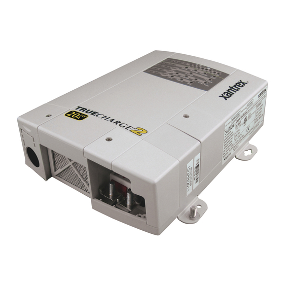
Introduction Truecharge™ 2 Battery Charger This section describes the different parts of the Truecharge™ 2 Battery Charger. Figure 1-1 Truecharge™ 2 Battery Charger Item Description Onboard control and status display panel or simply onboard display (see “Rear Panel” on page 1–6 for more information) for controlling the Truecharge™... - Page 21 Truecharge™ 2 Battery Charger Item Description Fuse access panel cover provides access to the DC fuse in the event of an accidental reverse battery polarity installation. WARNING: Shock hazard Disconnect the batteries and AC power before opening the fuse access panel. AC wiring compartment cover provides the installer with easy access to the AC wiring compartment, to allow for a trouble free installation.
-
Page 22: Rear Panel
Introduction Rear Panel This section describes the parts of the rear panel of the Truecharge™ 2 Battery Charger. 40 A model (TC4012) shown. Other models may vary. Figure 1-2 Truecharge™ 2 Battery Charger Rear Panel Item Description BTS port- battery temperature sensor port Communication port - remote panel port Battery positive (+) for bank 3 (6 mm stud) Battery positive (+) for bank 2 (6 mm stud) - Page 23 Rear Panel Please see the Truecharge™ 2 Battery Charger Owner’s Guide (doc. part number: 975-0401-01-01) for information on the following: 1. Onboard Control and Status Display Panel 2. Fault and Warning Indicators 3. Remote Panel 975-0402-01-01 1–7 This guide for use by qualified installers only Downloaded from Elcodis.com electronic components distributor...
- Page 24 1–8 This guide for use by qualified installers only Downloaded from Elcodis.com electronic components distributor...
-
Page 25: Installation
Installation Chapter 2 provides procedures for installing, testing and configuring the Truecharge™ 2 Battery Charger. It covers the following major topics: • “Preparing for Installation” on page 2–2. • “Installing the Truecharge™ 2 Battery Charger” on page 2–13 • “Installing Optional Accessories” on page 2–25 •... -
Page 26: Preparing For Installation
Installation Preparing for Installation WARNING The battery charger must be installed by a qualified installer in accordance with all applicable local or national installation codes. Examples of such codes are the US National Electrical Code (NFPA 70), the American Boat and Yacht Council standards E-11 and A-31, and the US Coast Guard Electrical Regulations (33CFR183). - Page 27 Preparing for Installation NOTE: Not to scale. For illustration purposes only. NOTE: In some jurisdictions a double-pole breaker may be required. Figure 2-1 Typical Truecharge™ 2 Battery Charger System Installation AC mains source protected by correct size and type of branch rated circuit breaker AC input wiring compartment DC negative cable...
-
Page 28: Tools And Materials
Installation Tools and Materials To mount and connect the Truecharge™ 2 Battery Charger you need the following tools: • 10 mm socket wrench and extension for the DC terminals and ground stud • Phillips screwdriver for removing and re-securing the AC and DC wiring compartment covers •... -
Page 29: Location
This battery charger is ignition protected, so it can be installed in areas containing gasoline tanks or fittings which require ignition protected equipment. Xantrex recommends, however, that it is safest not to install electrical equipment in these areas. Close to The Truecharge™... - Page 30 Installation When planning to install the Truecharge™ 2 Battery Charger, be sure that you consider the location and orientation carefully. The Truecharge™ 2 Battery Charger is considered to have an IP rating of IP-32, if installed in either of two specific orientations [shown in Figure 2-2 a) and b)].
- Page 31 Preparing for Installation Deck Mount - this orientation meets IP-32 requirements and is drip-proof. Horizontal Wall Mount (with AC wiring higher than DC terminals only) - this orientation meets IP-32 requirements and is drip-proof. Vertical Wall Mount (Rear panel facing down or up) - this orientation is allowed in locations that are always dry but is approved for marine installations only with additional drip protection.
-
Page 32: Wiring Requirements
Installation Wiring Requirements WARNING: Shock and fire hazard Wiring and fuse sizes are governed by electrical codes and standards. Different requirements apply in different countries and to different types of installations, for example, boat, home or RV. It is the responsibility of the installer to ensure that each installation complies with all applicable codes and standards. - Page 33 Preparing for Installation Table 2-2 DC Wiring Examples for 24 V chargers Wire Length Wire Size (AWG and mm max length one way TC1524 TC2024 TC3024 TC5024 feet meters No. 14 No. 10 No. 10 No. 6 2 mm 5.3 mm 5.3 mm 13.3 mm 2.25...
-
Page 34: Ac Wiring
Installation Table 2-3 Fuse Sizes versus Wire Sizes Based on ABYC Regulations Max. Fuse/Breaker 15 A 20 A 30 A 50 A 80 A 100 A 125 A 150 A The DC chassis ground (earth) wire should also be sized correctly to provide proper protection. - Page 35 Preparing for Installation a minimum of 75C, and sized based on the AC input current to the charger (see Appendix A) and on the value of overcurrent protection provided. For example, in US NEC, you may use a 14 AWG wire with a 15 A breaker for up to 12 A continuous current (or 12 AWG for a 20 A breaker for up to 16 A continuous current) or for 230 Vac application, you may be able to use either a 2.5mm...
-
Page 36: Battery Bank Size Requirements
Installation Battery Bank Size Requirements The Truecharge™ 2 Battery Charger is designed to work with a minimum battery bank size. Each bank should meet the minimum Ah rating shown in Table 2-4. Note: If the battery manufacturer has specified the maximum charge current, please follow their recommendation. -
Page 37: Installing The Truecharge™ 2 Battery Charger
Disconnect all sources of AC and DC power before proceeding. Installation Sequence To make charger installation quick and easy, Xantrex recommends that the installation tasks be performed in the following sequence: 1. Mount the charger in position. -
Page 38: Mounting The Truecharge™ 2 Battery Charger
Installation Mounting the Truecharge™ 2 Battery Charger Mount the Truecharge™ 2 Battery Charger using all four mounting slots and holes which are provided. Mounting orientations a) and b) in Figure 2-2 meet IP-32 and drip-proof requirements that are needed to ensure safety in the presence of condensation. -
Page 39: Connecting The Dc Chassis Ground (Earth)
Xantrex recommends that you install a DC chassis ground (earth) wire from the ground stud on the Truecharge™ 2 Battery Charger to the engine bus or DC ground bus. The DC... -
Page 40: Installing Dc Wiring
Installation Installing DC Wiring The procedure for installing the DC wiring applies to a single battery, as well as multiple batteries or battery banks. WARNING: Energy and explosion hazard To help prevent accidental shorts or sparks, leave the DC disconnects or breakers in the Off position or DC fuses removed from their fuse holders until installation is complete. - Page 41 Installing the Truecharge™ 2 Battery Charger WARNING: Shock hazard The rubber boots must be installed over the Truecharge™ 2 Battery Charger DC terminals to keep water off of live parts and to maintain the chargers' IP-32 and drip-proof ratings. 5. Insert and slide the rubber boot(s) over the charger end of the DC battery cables.
- Page 42 Installation 7. Connect the negative cable to the negative DC terminal. See Figure 2-1, “Typical Truecharge™ 2 Battery Charger System Installation” on page 2–3. For one battery or bank ◆ Connect the negative cable from the negative terminal on the battery to the negative DC terminal on the Truecharge™...
- Page 43 Installing the Truecharge™ 2 Battery Charger 13. Secure cables in place using tie-wraps or cable straps according to electrical codes. 14. Slide the rubber boots to cover the DC terminals. 15. If available, route the optional battery temperature sensor (BTS) from the battery (one which is located in the warmest ambient temperature) to the charger location.
-
Page 44: Installing Ac Wiring
Installation Installing AC Wiring Before connecting AC wiring, make sure the AC source circuit is protected by a breaker switch of the correct size and type, to comply with the electrical code for your location and application. The current rating of the input breaker should not be larger than 20 A for 120 Vac applications and 16 A for 230 Vac applications, but may be required to be lower depending on the wire size used. - Page 45 Installing the Truecharge™ 2 Battery Charger 5. Carefully remove 50 – 75 mm (2 – 3 in.) of the outer jacket from the AC supply wiring, being careful not to cut or nick the insulation on the individual conductors. 6. Extend the charger’s AC (L, N, ) pigtail leads (wires) from the AC wiring compartment of the charger.
- Page 46 Installation To connect AC wires with the provided crimp-on butt-splice connector: a) Make the connections using the provided crimp-on connectors or with other approved connectors required by your code, and suitable for your installation. For example, the ABYC Standards and Recommended Practices for Small Craft prohibit twist-on connectors for AC connections on a boat.
- Page 47 Installing the Truecharge™ 2 Battery Charger 10. When all connections are completed, push the wiring and connectors inside the AC wiring compartment. 11. Place the strain relief on the AC wiring access hole. 12. Install the wiring compartment cover to fasten the strain relief and tighten the screw on top to secure the cover.
-
Page 48: Powering
Installation Powering Up Make one last check that all connections are correct and connectors are secure. The Truecharge™ 2 Battery Charger charger may now be powered up. 1. Close the DC disconnect switch or breaker. WARNING: Fire hazard The final connection of the DC battery circuit will generate an arc. Ensure all areas of the system, including batteries and engine compartments, are well ventilated prior to making this connection. -
Page 49: Installing Optional Accessories
Installing Optional Accessories Installing Optional Accessories Optional accessories are available for purchase at Xantrex. Call Customer Service to order the accessories below: • Battery Temperature Sensor (Part number: 808-0232-01) • Remote Panel (Part number: 808-8040-00) Installing the Optional Battery Temperature Sensor... -
Page 50: Mounting The Optional Remote Panel
Installation Mounting the Optional Remote Panel To mount the remote panel: 1. Choose a location for the remote panel that is within 15 m (50 ft.) from the charger. Use only the six-conductor communications cable (RJ-12) that came with the remote panel. 2. -
Page 51: Configuring The Truecharge™ 2 Battery Charger
Configuring the Truecharge™ 2 Battery Charger Configuring the Truecharge™ 2 Battery Charger Once the charger is connected to a battery on bank 1 or to AC, it is live and it may be configured. The indicator LEDs on the onboard display will illuminate for a second (power on test) before reporting charging and battery status information. - Page 52 Installation Using the Remote Panel To configure the charger mode: Note: By default, the Charger Mode is set to three-stage. 1. Press and hold the Status button for five seconds to enter the Setup mode. Entering the Setup mode will enable you to select the charger mode.
-
Page 53: Configuring The Battery Bank Type
Configuring the Truecharge™ 2 Battery Charger Configuring the Battery Bank Type Using the Onboard Display Panel To configure the battery bank type: Note: By default, the battery type is set to Flooded. 1. Press and hold the Battery Type Select button for three seconds to advance to the next setting. -
Page 54: Configuring The Maximum Output Current
Installation Configuring the Maximum Output Current Percentage Advantages of Current Limiting Feature: • Gives the user flexibility to custom charge according to the battery manufacturer’s instructions. • Allows batteries with a lower current rating to be charged safely without the need of a new charger. •... -
Page 55: Installing Batteries
Installing Batteries Installing Batteries Replacing old or defective batteries (even installing new batteries) requires that you disconnect all AC and DC sources prior to installation. WARNING Battery installation should always be treated like a brand new installation. This means, that all safety and precautionary guidelines that were followed prior and during the installation of the charger, must again be followed in order to avoid risks of electrical shock, injury, or death. - Page 56 2–32 This guide for use by qualified installers only Downloaded from Elcodis.com electronic components distributor...
- Page 57 Specifications Appendix A contains physical, electrical performance, and regulatory approval specifications for the Truecharge™ 2 Battery Charger. Note: Specifications are subject to change without notice. This guide for use by qualified installers only Downloaded from Elcodis.com electronic components distributor...
-
Page 58: Physical Specifications
Specifications Physical Specifications Base Unit TC1012, TC1512: Dimensions: 200 × 170 × 70mm (7.87 × 6.70 × 2.76 in.) L × W × H TC2012, TC3012, TC4012: 250 × 170 × 70mm (9.84 × 6.70 × 2.76 in.) TC5012, TC6012: 350 ×... -
Page 59: Electrical Specifications
Electrical Specifications Electrical Specifications AC Input Specifications AC input voltage range Nominal: 120 Vac, 230 Vac, 240 Vac Full Performance: 104 – 265 Vac ±4 Vac Automatic derating to 80% output: 90 – 108 ±4 Vac Maximum AC input at 104 Vac at 230 Vac –... -
Page 60: Dc Output Specifications
Specifications DC Output Specifications Number of isolated battery TC1012: bank outputs 1 output TC1512: 2 separated outputs TC2012, TC3012, TC4012, TC5012, TC6012, TC1524, TC2024, TC3024, TC5024: 3 separated outputs DC output voltage range 12 Vdc units: 0 – 15.5 Vdc including dead battery 24 Vdc units: 0 –... -
Page 61: Environmental Specifications
Environmental Specifications Absorption voltage: 12 Vdc units 24 Vdc units ±0.1 V for 12 Vdc units 25 °C (77 °F) 25 °C (77 °F) ±0.2 V for 24 Vdc units Flooded 14.4 28.8 14.2 28.4 14.3 28.6 Lead-calcium 15.5 31.0 Float voltage: 12 Vdc units 24 Vdc units... -
Page 62: Protection Features
Specifications Protection Features Battery reverse Protected by replaceable DC output fuses polarity Over-voltage limits The Truecharge™ 2 Battery Charger will stop charging if the output voltage is above 16.6 ±0.5 Vdc. Output current limit TC1012: 10 +10% A TC1512: 15 +10% A TC2012: 20 +10% A TC3012:... -
Page 63: Approvals
Approvals Approvals Safety NRTL approved to CSA E60335-2-29, UL1236, including the marine supplement, ignition protection, and UL1564 CE marked for the Low Voltage Directive 2006-95-EC, (complying with EN60335-2-29 Battery Chargers) Designed to IEC60335-2-29 including Australian deviations, ISO 8846: Ignition Protection for Small Craft, ABYC E11 - Alternating Current and Direct Current Electrical Systems on Boats, and ABYC A31 - Battery Chargers and Inverters... - Page 64 A–8 This guide for use by qualified installers only Downloaded from Elcodis.com electronic components distributor...
- Page 65 Downloaded from Elcodis.com electronic components distributor...
- Page 66 Xantrex Technology Inc. 1 800 670 0707 Tel toll free NA 1 408 987 6030 Tel direct +34 93 470 5330 Europe 1 800 994 7828 Fax toll free NA +34 93 473 6093 Europe customerservice@xantrex.com www.xantrex.com 975-0402-01-01 Printed in China Downloaded from Elcodis.com...
Need help?
Do you have a question about the Truecharge2 Series and is the answer not in the manual?
Questions and answers