Omron G9SP-N20S Operation Manuals
G9sp series g9sp-n series safety controller
Hide thumbs
Also See for G9SP-N20S:
- Network connection manual (58 pages) ,
- Connection manual (22 pages) ,
- Manual (19 pages)
Table of Contents
Advertisement
Quick Links
Advertisement
Chapters
Table of Contents
Troubleshooting

Subscribe to Our Youtube Channel
Related Manuals for Omron G9SP-N20S


Summary of Contents for Omron G9SP-N20S
- Page 1 Cat. No. Z922-E1-07 G9SP Series Safety Controller OPERATION MANUAL...
- Page 2 No patent liability is assumed with respect to the use of the information contained herein. Moreover, because OMRON is constantly striving to improve its high-quality products, the information contained in this manual is subject to change without notice. Every precaution has been taken in the preparation of this manual. Neverthe- less, OMRON assumes no responsibility for errors or omissions.
- Page 3 G9SP-series Safety Controller: G9SP-N@@@ Operation Manual Revised December 2016...
-
Page 5: Table Of Contents
TABLE OF CONTENTS Introduction ..............Manual Configuration . - Page 6 TABLE OF CONTENTS Hardware Settings SECTION 4 Installation and Wiring ......Installation ............. . . Wiring .
- Page 7 TABLE OF CONTENTS Software Design SECTION 8 Connecting Online and Downloading to the G9SP-series Controller ........131 Overview .
- Page 8 TABLE OF CONTENTS Maintenance and Inspections SECTION 12 Maintenance and Inspections ......169 12-1 Inspections ............. . . 12-2 G9SP-series Controller Replacement Precautions.
- Page 9 Introduction Thank you for purchasing a G9SP-series Safety Controller. This manual contains information required to use the G9SP-series Controller. Please thoroughly read and understand this manual before you use the G9SP-series Controller. Intended Audience This manual is intended for the following personnel, who must also have knowledge of electrical systems (an electrical engineer or the equivalent).
- Page 10 Manual Configuration Information on the operation of G9SP-series Safety Controllers is provided in the following manuals. Refer to the specific manual depending on the information that is required. Manual name Contents Cat. No. G9SP-series Safety This manual provides detailed specifications and describes functions Z922 Controller Operation and application methods for the G9SP-series Controller in detail.
-
Page 11: Installation And Wiring
Sections in this Manual Checking Operating Overview Status and Debugging Part Names and Backup and Restore Data Specifications Using Memory Cassette Maintenance and Calculating Response Inspections Performance Troubleshooting Installation and Wiring Preparations for Using Application Templates the G9SP Configurator Creating Configuration Data Communications with a Standard PLC Using an Option Board Connecting Online and Downloading to the... - Page 13 Products were properly handled, stored, installed and maintained and not subject to contamination, abuse, misuse or inappropriate modification. Return of any Products by Buyer must be approved in writing by Omron before ship- ment. Omron Companies shall not be liable for the suitability or unsuitability or...
- Page 14 Data presented in Omron Company websites, catalogs and other materials is provided as a guide for the user in determining suitability and does not consti- tute a warranty. It may represent the result of Omron’s test conditions, and the user must correlate it to actual application requirements. Actual performance is subject to the Omron’s Warranty and Limitations of Liability.
- Page 15 Safety Precautions Definition of Precautionary Information The following notation is used in this manual to provide precautions required to ensure safe usage of a G9SP-series Controller. The safety precautions that are provided are extremely important to safety. Always read and heed the information provided in all safety precautions. The keywords and their definitions are as given below.
- Page 16 WARNING This is the Operation Manual for the G9SP-series Safety Controllers. Obey the following warnings during system construction to ensure that safety-related components are configured to enable the system functions to sufficiently operate. ● Risk Assessment The proper use of the safety devices described in this manual as they relate to installation conditions and mechanical performance and functions is a prerequisite for its use.
- Page 17 WARNING Electric shock may occur. Do not touch any terminals while power is being supplied. Serious injury may possibly occur due to loss of required safety functions. Do not use the G9SP-series Controller's test outputs or standard outputs as safety outputs. Serious injury may possibly occur due to loss of required safety functions.
-
Page 18: Installation
Precautions for Safe Use ● Handling Do not drop the G9SP-series Controller or subject it to excessive vibration or mechanical shock. The G9SP-series Controller may be damaged and may not function properly. ● Installation and Storage Environment Do not use or store the G9SP-series Controller in any of the following locations: •... - Page 19 Turn OFF the power supply before performing any of the following. • Connecting or disconnecting Expansion I/O Units, Option Boards, or any other Units • Assembling the G9SP-series Controller • Connecting cables or wiring • Connecting or removing terminal blocks ●...
- Page 20 ● Power Supply Selection Use a DC power supply satisfying the following requirements. • The secondary circuit of the DC power supply must be isolated from the primary cir- cuit by double insulation or reinforced insulation. • The output characteristic requirements defined in UL 508 for class 2 circuits or con- trol voltage current circuits are satisfied.
- Page 21 I/O power. Connect both of them to the same power source. ● Ratings Controller Rating for UL G9SP-N20S Source: 24 V dc, 500 mA, isolated source Input: 24 V dc, 6 mA /P, 20 points Output: 24 V dc (GEN) (P.D.), 0.8 A /P, 8 points Rated total currents of So0 to 3, So4 to 7 are 1.6 A each...
- Page 22 • Machinery Directive (2006/42/EC) Concepts ● EMC Directive OMRON electrical devices are built into other components or equipment. OMRON therefore pursues compliance with the related EMC standards so that they can be more easily built into other devices or the equipment.*...
- Page 23 Safety Controller. The customer must implement measures to ensure compliance with these standards. To obtain the reliability data for safety of machinery to verify the safety performance of your equipment, go to the following URL: http://www.ia.omron.com/support/sistemalibrary/index.html. xxiii...
-
Page 24: Creating Configuration Data
Expansion I/O Unit The name of the CP1W-20EDT(-1) and CP1W-32ET(-1). Some of the OMRON CP1-series Expansion I/O Units can be used in a G9SP-series Controller. Expansion I/O Units are connected to a G9SP-series Controller to increase the number of Standard I/O points. - Page 25 Acronyms Acronym Meaning Memory Cassette. Safety Input. An input from a Safety Input terminal. This term is used to differentiate from a Standard Input (IN). Safety Output. An output from a Safety Output terminal. This term is used to differentiate from a Standard Output (OUT).
- Page 26 xxvi...
-
Page 27: Overview
Overview SECTION 1 Overview This section provides an overview and describes the features, system configuration, and application procedures for the G9SP-series Controller. Overview and Features of the G9SP-series Controller ....1-1-1 Overview. -
Page 28: Overview And Features Of The G9Sp-Series Controller
Overview and Features of the G9SP-series Controller Section 1-1 Overview and Features of the G9SP-series Controller 1-1-1 Overview The G9SP-series Safety Controller is a programmable controller that is designed for easy operation in small to mid-sized Safety Control systems. Using the G9SP-series Safety Controller enables building Safety Control sys- tems that satisfy the requirements for SIL 3 (Safety Integrity Level 3) in IEC 61508 (Safety Standard for Safety Instrumented Systems: Functional Safety of Electrical/Electronic/Programmable Electronic Safety-related Systems) and... - Page 29 There are three models of G9SP-series Controllers depending on the number of Safety I/O points. Name/model G9SP-N10S G9SP-N10D G9SP-N20S Appearance W66 x H110 x D65 (mm) W130 x H110 x D85 (mm) W130 x H110 x D85 (mm) Power supply...
- Page 30 CP1W-CIF41 (unit version 2.0 or later) Appearance IP ADDRESS: COMM SUBNET MASK: COMM ERR 10BASE-T 100BASE-TX Protocol No-protocol UDP/IP Communications with an OMRON Standard PLC can be performed using FINS/UDP. Memory Cassette The CP1W-ME05M CP-series Memory Cassette can be used.
- Page 31 Safety Relays and Safety Contactors. Direct Connection to Safety Devices A direct connection can be made to an OMRON UM Safety Mat, a D40A or D40Z Non-contact Switch, or an E3ZS/E3FS Single Beam Safety Sensor. Connecting without use of an intermediate special controller enables reducing control panel size and decreasing system costs.
- Page 32 Section 1-1 Overview and Features of the G9SP-series Controller Adding Standard I/O Using Expansion I/O Units Using Standard Expansion I/O Units enables achieving signal transfer with Standard Control at a low cost. Support Software for Robust Support from Design to Startup Efficiency from design to startup can be greatly improved by using the func- tions of the G9SP Configurator.
- Page 33 Overview and Features of the G9SP-series Controller Section 1-1 Force-setting/Force-resetting • Force-setting/resetting lets you turn the I/O tags ON and OFF in the pro- gram regardless of whether I/O devices and communications data are ON or OFF. During system development, programming can be debugged without I/O devices and remote communications.
- Page 34 Section 1-1 Overview and Features of the G9SP-series Controller Access Management Using Parameter Passwords Access to project files created by the G9SP Configurator can also be man- aged using passwords. This prevents unintended changes to project files as well as disabling access to configuration data uploaded from the G9SP-series Controller.
-
Page 35: Designing Device Security
Section 1-2 Basic Operating Procedures Basic Operating Procedures Generally, the following procedures are used for operation. System Design 1. Determining Safety Measures by Conducting Risk Assessment Section 2 Part Names and Specifications 2. Selecting Safety Devices 3. Designing Device Security 6-3 Designing Device Security 4. - Page 36 Section 1-2 Basic Operating Procedures...
-
Page 37: Part Names And Specifications
Hardware Settings SECTION 2 Part Names and Specifications This section provides the names of G9SP-series Controller parts, specifications, and terminal arrangements. G9SP-series Controllers ......... 2-1-1 Part Names and Indicators . -
Page 38: G9Sp-Series Controllers
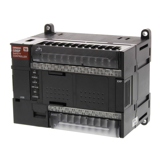
(8) I/O Indicators (2) USB Port (8) I/O Indicators (9) Terminal Block (3) Push Switch (4) DIP Switch G9SP-N10D G9SP-N20S (6) Option Board Slot (8) I/O Indicators (7) Expansion I/O Unit Connector (9) Terminal Block (1) Operation Indicators (2) USB Port... - Page 39 Section 2-1 G9SP-series Controllers Name Function Operation Indicators These indicators can be used to check the operating status of the G9SP-series Control- ler. Connect a USB cable to this port to connect to a computer to set up and monitor the USB Port G9SP-series Controller from the G9SP Configurator.
- Page 40 G9SP-series Controllers Section 2-1 Operation Indicators This section describes the operation indicators that are provided on the G9SP-series Controller. Refer to sections on individual functions for details. : OFF : Flashing : ON Indicator Color Status Description MS (Module Status) Green Operating (RUN Mode) Idle (IDLE Mode) FORCE...
- Page 41 Section 2-1 G9SP-series Controllers Precautions for Safe Use If the MC indicator is flashing at 0.25-s intervals, it indicates that the Memory Cassette is being accessed (read or written). Do not turn OFF the internal circuit power supply to the G9SP-series Control- ler or remove the Memory Cassette until the indicator stops flashing.
-
Page 42: Terminal Arrangements
Terminal Arrangements G9SP-N10S (17 pins) Bottom (14 pins) G9SP-N10D (24 pins) Bottom So10 So12 So14 (19 pins) So11 So13 So15 G9SP-N20S Si11 Si13 Si15 Si17 Si19 (24 pins) Si10 Si12 Si14 Si16 Si18 Bottom (19 pins) G2 So1 Internal Circuits and Wiring Diagram 24 VDC D−... -
Page 43: General Specifications
Terminal screws M3 self-rising screws The current consumption of external devices is not included. 2-1-4 I/O Specifications I/O Capacities Item G9SP-N10S G9SP-N10D G9SP-N20S Safety Inputs 10 points 10 points 20 points Safety Outputs 4 points 16 points 8 points Test Outputs... - Page 44 ON residual voltage 1.8 V max. (between test outputs and V1) Leakage current 0.1 mA max. Connection to an OMRON D40A or D40Z Non-Contact Switch is possi- ble. With the Muting Lamp Output (open circuit detection) Safety Output Specifications Item...
- Page 45 Section 2-1 G9SP-series Controllers Standard Output Specifications of G9SP-N10S Item Specification Output type Sourcing outputs (PNP) ON residual voltage 1.5 V max. (between outputs and V2) Rated output current 100mA max. Input Wiring Devices with Contact Outputs A devices with a contact output, such as an emergency stop pushbutton or safety limit switch, is input to the G9SP-series Controller using a Safety Input terminal (Si) and Test Output terminal (To).
-
Page 46: Safety Inputs
Safety Devices with semi- Safety curtains and laser scanners conductor outputs Standard Devices Limit switches and muting sensors The following OMRON Safety Devices can be connected directly without spe- cial controllers. Type Model and category/PL OMRON Single Beam E3ZS and E3FS (Conforms to Safety Category 2 and Safety Sensor PLc.) - Page 47 G9SP-series Controllers Section 2-1 Setting Safety Input Terminals A Safety Input terminal on the G9SP-series Controller can be easily set by selecting the connected external device on the G9SP Configurator. (For details, refer to 6-2-2 Hardware Settings.) The selected connection devices are displayed. I/O comments are treated as names and can be used in the program.
- Page 48 Control output 2 (OSSD 2) G9SP Configurator Setting Example Connecting an OMRON E3ZS/E3FS Single Beam Safety Sensor This section describes connecting an OMRON E3ZS/E3FS Single Beam Safety Sensor. Wiring Example The OSSD 24-VDC semiconductor output from the Single Beam Safety Sen- sor is input.
- Page 49 Section 2-1 G9SP-series Controllers Precautions for Correct Use • Only one E3ZS/E3FS Single Beam Safety Sensor can be connected to a G9SP-series Safety Controller with unit version 1.0 or unit version 1.1. The maximum number of E3ZS/E3FS Single Beam Safety Sensors that can be connected to a G9SP-series Safety Controller with unit version 2.0 or later is as follows: G9SP-N10S: 4 (1 Sensor ×...
- Page 50 Switch. Wiring Example The non-contact switch output (black line) from the OMRON D40A or D40Z Non-contact Switch is input to a Safety Input terminal. This is a one-line sig- nal. When connecting it to the G9SP-series Controller, branch it, as shown for Si0 and Si1 in the following diagram.
- Page 51 Section 2-1 G9SP-series Controllers Precautions for Correct Use • The maximum number of Switches that can be connected to a G9SP-series Controller is given below. G9SP-N10S: 15 (15 × 1 system) G9SP-N10D/20S: 30 (15 × 2 system) • The following Test Output terminals must be used to connect to the D40A or D40Z Non-contact Switch.
- Page 52 Section 2-1 G9SP-series Controllers Connecting an OMRON UM Safety Mat This section describes connecting an OMRON UM Safety Mat. Wiring Example A Safety Output from the UM Safety Mat is connected to a Safety Input termi- nal. For the UM, only 1 system can be set and up to 12 Mats can be con- nected in series.
- Page 53 G9SP-series Controllers Section 2-1 Connecting an OMRON MC3 Mat Controller This section describes connecting an OMRON MC3 Safety Mat Controller. Wiring Example A Safety Output from the MC3 Safety Mat Controller is connected to Safety Input terminals. MC3 Safety Mat Controller...
- Page 54 Section 2-1 G9SP-series Controllers Functions of Safety Input Terminals This section describes the functions of the Safety Input terminals on the G9SP-series Controller. The following functions are allocated automatically when the external devices to connect are selected from the G9SP Configura- tor.
- Page 55 Section 2-1 G9SP-series Controllers Test Pulse Evaluation A test pulse with a specific period is output on the 24-V power line from a Test Output terminal to detect wiring errors and failure of the externally connected device. The following parameters are also used. •...
- Page 56 Switch signals for the D40A or D40Z will be output. Safety Mat An OMRON UM Safety Mat is connected. Test signals for diagnos- ing the Safety Mat will be output. Dual Channel Evaluation Input safety terminals can be used as dual channels (one pair) for the G9SP- series Controller.
- Page 57 Section 2-1 G9SP-series Controllers Single/dual Input signal from Value after Meaning of status Safety Input evaluation terminal Si (n) Si (n+1) Si (n) Si (n+1) Dual Channel Inactive (OFF) Equivalent Discrepant status Discrepant status Active (ON) Dual Channel Discrepant status Complementary Inactive (OFF) Active (ON)
- Page 58 Section 2-1 G9SP-series Controllers Input Filters ON delays and OFF delays can be set to prevent malfunctions caused by noise or by chattering of externally connected devices. ON delays and OFF delays can be set for each terminal from 0 to 1,000 ms. The effect of chattering from external devices can be reduced more by increasing the delay time, but this will slow the response to input signals.
- Page 59 Section 2-1 G9SP-series Controllers Operation at Error Detection When the G9SP-series Controller detects an error in the Safety Input termi- nals, the following operations will take place. • The Safety Input evaluation data that is passed to the program is made inactive.
-
Page 60: Safety Outputs
Section 2-1 G9SP-series Controllers 2-1-6 Safety Outputs This section describes the Safety Output functions of the G9SP-series Con- trollers Safety I/O functions. The G9SP-series Controller diagnoses the exter- nal devices connected to Safety Output terminals. Devices That Can Be Connected The following table lists the devices that can be connected. - Page 61 Section 2-1 G9SP-series Controllers External Device Connection Examples Refer to the following information when connecting output devices. 0.8 A max. 24 VDC G9SP-series So0 to So15 Controller !WARNING Serious injury may possibly occur due to breakdown of safety outputs or test outputs.
- Page 62 Section 2-1 G9SP-series Controllers Functions of Safety Output Terminals This section describes the functions of the Safety Output terminals on the G9SP-series Controller. The following functions are allocated automatically when the external devices to connect are selected from the G9SP Configura- tor.
- Page 63 Section 2-1 G9SP-series Controllers Diagnosis The parameter determines whether test pulse evaluation is used. The errors that can be detected are determined by the setting of this parameter. Channel Description Fault Mode mode of operation Contact with positive Ground faults Short circuits in output wiring side of power line Output ON...
- Page 64 Section 2-1 G9SP-series Controllers Relationship between Output Tags The data of the output tags that are used in the program are output to the Safety Output terminals according to the single/dual channel setting as shown below. Single/dual Output tag value Output signal from Meaning of status the Safety Output...
- Page 65 Section 2-1 G9SP-series Controllers Operation at Error Detection The G9SP-series Controller performs the following actions if an error is detected in the Safety Output terminals: • The outputs to external devices are immediately made inactive regardless of the status of the user program. •...
-
Page 66: Expansion I/O Units
Section 2-2 Expansion I/O Units Expansion I/O Units This section provides the names of Expansion I/O Unit parts, I/O specifica- tions, and terminal arrangements. Refer to 4-1 Installation and 4-2 Wiring for dimensions and weights. 2-2-1 Part Names and Indicators Part Names and Functions Standard I/O Units with 20 I/O Points (CP1W-20EDT/20EDT1) 4. - Page 67 Expansion I/O Units Section 2-2 I/O Indicators : OFF : ON Indicator Color Status Description IN0 to INn Yellow The input signal is ON. n: Terminal number (Standard Input terminals) The input signal is OFF. OUT0 to OUTn Yellow The output signal is ON. n: Terminal number (Standard Output terminals) The output signal is OFF.
-
Page 68: Terminal Arrangements
Expansion I/O Units Section 2-2 2-2-2 Terminal Arrangements Standard I/O Units with 20 I/O Points (CP1W-20EDT/20EDT1) ■ Input (Unit Upper Terminal Block) COM: Common terminal 00 to 11: Input terminal NC: No connection ■ Output (Unit Lower Terminal Block) COM: Common terminal 00 to 07: Output terminal COM COM COM Standard Output Units with 32 I/O Points (CP1W-32ET/32ET1) - Page 69 Section 2-2 Expansion I/O Units ■ Output Terminals ■ CP1W-20EDT (Sinking Transistor Outputs) Unit Lower Terminal Block COM: Common terminal 00 to 07: Output terminals ■ CP1W-20EDT1 (Sourcing Transistor Outputs) Unit Lower Terminal Block COM: Common terminal 00 to 07: Output terminals Wiring Diagrams: Standard Output Units with 32 I/O Points (CP1W-32ET/32ET1) ■...
- Page 70 Expansion I/O Units Section 2-2 Unit Lower Terminal Block COM: Common terminal 16 to 31: Output terminals NC: No connection ■ CP1W-32ET1 (Sourcing Transistor Outputs) Unit Upper Terminal Block COM: Common terminal 00 to 15: Output terminals NC: No connection Unit Lower Terminal Block COM: Common terminal 16 to 31: Output terminals...
-
Page 71: I/O Specifications
Section 2-2 Expansion I/O Units 2-2-3 I/O Specifications This section describes the I/O specifications of Expansion I/O Units. Input Specifications (CP1W-20EDT/20EDT1) Item Specification Input voltage 24 VDC, +10%, -15% Input impedance 4.7 kΩ Input current 5 mA typical ON voltage 14.4 VDC min. - Page 72 Section 2-2 Expansion I/O Units Output Specifications for Transistor Outputs (Sinking or Sourcing) Item Specification CP1W-20EDT/20EDT1 CP1W-32ET/32ET1 Maximum switching 24 VDC 4.5 to 30 VDC +10%/-5% 0.3 A/output capacity 0.3 A/output 0.9 A/common 0.9 A/common 1.8 A/Unit 7.2 A/Unit Leakage current 0.1 mA max.
-
Page 73: Current Consumption
Expansion I/O Units Section 2-2 2-2-4 Current Consumption Unit Model Current consumption 5 VDC 24 VDC Expansion I/O 20 I/O points CP1W-20EDT 0.130 A Units Inputs: 12 CP1W-20EDT1 Outputs: 8 32 output points CP1W-32ET 0.113 A CP1W-32ET1... -
Page 74: Option Units
Section 2-3 Option Units Option Units The section describes the part names, connector arrangement, communica- tions specifications, and other information on Option Units. Refer to 4-1 Installation and 4-2 Wiring for dimensions and weights. 2-3-1 RS-232C Option Board (CP1W-CIF01) Part Names and Connector Arrangement Front Rear 1. -
Page 75: Ethernet Option Board (Cp1W-Cif41)
Section 2-3 Option Units Item Specification Connection method D-sub, 9-pin female connector Maximum transmission distance With a baud rate of 9,600 bps: 15 m With a baud rate of 115,200 bps: 3 m Communications protocol No-protocol Maximum data length SECTION 7 Communications with a Standard PLC Using an Option Board Frame format Start code... -
Page 76: Memory Cassette (Cp1W-Me05M)
Weight 23 g max. Dimensions 36.4×36.4×28.2 mm (W×H×D) Note Communications with OMRON PLCs can be performed using the FINS/UDP protocol. 2-3-3 Memory Cassette (CP1W-ME05M) Refer to SECTION 11 Backup and Restore Data Using Memory Cassette for information on using a Memory Cassette with the G9SP-series Controller. -
Page 77: Calculating Response Performance
Hardware Settings SECTION 3 Calculating Response Performance This section describes the startup time and reaction time of the G9SP-series Controller. Startup Time ..........Reaction Times . -
Page 78: Startup Time
Section 3-1 Startup Time Startup Time This section describes the operating flow and startup time of the G9SP-series Controller. Operation Flow The following flowchart shows the operation cycle of the G9SP-series Control- ler. Power ON Initialization System processing Input refresh Cycle time User application processing (depends on... -
Page 79: Reaction Times
Section 3-2 Reaction Times Reaction Times This section describes how to calculate reaction times (safety response per- formance) for the G9SP-series Controller. 3-2-1 Reaction Time Concepts Reaction Time The reaction time is the time required to stop machine operation in a worst- case scenario considering the occurrence of faults and failures in the safety chain. - Page 80 Confirm that the calculated reaction times meet the required specifications for all safety chains. Additional Information The safety sensor/switch reaction times are given below for when the follow- ing OMRON Safety Sensors or Switches are connected directly to the G9SP- series Controller. Connected device Safety Sensor/Switch...
- Page 81 Hardware Settings SECTION 4 Installation and Wiring This section describes how to install and wire the G9SP-series Controller. Installation........... . 4-1-1 Installation Location .
-
Page 82: Installation
Section 4-1 Installation Installation This section provides precautions on the environmental factors that must be considered and the installation location of each G9SP-series Unit. 4-1-1 Installation Location Installation Environment Do not install the G9SP-series Controller in the following locations. • Locations subject to ambient temperatures lower than 0°C or higher than 55°C. - Page 83 Section 4-1 Installation Accessibility for Operation and Maintenance • To ensure safe access for operation and maintenance, separate the G9SP-series Controller as much as possible from high-voltage equipment and moving machinery. • The G9SP-series Controller will be easiest to install and operate if it is mounted at a height of 1.0 to 1.6 m above the floor.
-
Page 84: Unit Arrangement
Section 4-1 Installation 4-1-2 Unit Arrangement This section describes how to arrange the G9SP-series Controller Units. As shown in the following diagrams, Units can be arranged in one or two rows when Expansion I/O Units or Expansion Units are used. Arrangement in One Row Expansion I/O Units and Expansion Units can be installed in a side-by-side arrangement. -
Page 85: Installation
Weight G9SP-N10S 290 g max. G9SP-N10D 440 g max. G9SP-N20S 430 g max. Installation Height The installation height is approximately 90 mm. When a Connecting Cable is connected to an Option Board, however, the additional height must be included. Always allow for the additional height when considering the depth of the control panel in which the G9SP-series Controller is to be mounted. -
Page 86: Connecting Expansion I/O Units And Expansion Units
Section 4-1 Installation Mounting Brackets DIN Track Secure the DIN Track to the control panel using M4 screws at interval of 210 mm or less (6 holes or fewer). The tightening torque is 1.2 N·m. PFP-100N2 28-25 × 4.5 long holes 30±0.3 29.2 1000... - Page 87 Section 4-1 Installation 2. Insert the Expansion I/O Unit’s connecting cable into the G9SP-series G9SP-series Controller’s or the Expansion I/O Unit’s expansion connector. (2) Insert 3. Attach the cover to the G9SP-series Controller’s or the Expansion I/O Unit’s expansion connector. (3) Attach Precautions for Correct Use •...
-
Page 88: Mounting Option Boards
Section 4-1 Installation 4-1-5 Mounting Option Boards This section describes how to mount an Option Board. Mounting and Removal Mounting 1,2,3... 1. Turn OFF the power supply to the G9SP-series Controller. 2. Remove the cover to the Option Board slot. If you squeeze the top and bot- tom lock levers on the cover together to release the lock, you can remove the cover. -
Page 89: Wiring
Section 4-2 Wiring Wiring This section describes wiring methods for the G9SP-series Controller and CP-series Expansion I/O Units. 4-2-1 Wire Sizes Use the following wires to wire the power supply and external I/O devices to the G9SP-series Controller. Solid wire 0.32 to 0.82 mm , AWG22 to AWG18 0.32 to 0.5 mm... -
Page 90: Wiring The Power Supply
Section 4-2 Wiring 4-2-2 Wiring the Power Supply Wiring the Power Supply The G9SP-series Controller provides power terminals V1/G1 for the internal and input circuits and power terminals V2/G2 for the output circuits. Use a power supply with a voltage fluctuation range of 20.4 to 26.4 VDC. •... - Page 91 Section 4-2 Wiring Precautions for Correct Use • Wiring clippings can scatter when wiring. Leave the label attached to the top of the Unit when wiring to prevent the entry of foreign matter. • Remove the label after the completion of wiring to ensure proper heat dissi- pation.
- Page 92 Section 4-2 Wiring...
- Page 93 Software Design SECTION 5 Preparations for Using the G9SP Configurator This section describes the features and provides the installation procedure for the G9SP Configurator. The G9SP Configurator is a software application that is used to program and debug a G9SP-series Controller. Overview .
-
Page 94: Overview
Section 5-1 Overview Overview The G9SP Configurator is a software application that is used to initialize, pro- gram, monitor, and debug G9SP-series Controller. This section describes the features of the G9SP Configurator and its system requirements. 5-1-1 System Requirements and System Configuration System Requirements The following system is required to operate the G9SP Configurator. -
Page 95: G9Sp Configurator Functions
Section 5-1 Overview Precautions for Correct Use • The G9SP Configurator cannot be used if it is connected to an RS-232C Option Board or Ethernet Option Board. Always connect it directly to the USB port. • Do not turn OFF the power supply to the G9SP-series Controller or discon- nect the USB cable while online. -
Page 96: Installation
Section 5-2 Installation Installation This section describes the installation procedure that must be performed to use the G9SP Configurator. Precautions for Correct Use To install the software, log on as a user that meets the following conditions. • Administrator privileges •... - Page 97 Installation Section 5-2 Windows XP The procedure to install the driver on a Windows XP computer is given in this section. 1,2,3... 1. Turn ON the power supply to the G9SP-series Controller and connect the USB port on the G9SP-series Controller to a USB port on the computer using a USB cable.
- Page 98 1,2,3... 1. Open the Computer Management Window on the computer and select the Device Manager on the navigation pane. If OMRON-PLC is displayed as a universal serial bus controller, installation of the USB driver has failed. 2. Right-click on OMRON-PLC and select Delete to delete the driver. Rein- sert the USB cable to display the USB driver installation dialog box.
- Page 99 Section 5-2 Installation Windows Vista The procedure to install the driver on a Windows Vista computer is given in this section. 1,2,3... 1. Turn ON the power supply to the G9SP-series Controller and connect the USB port on the G9SP-series Controller to a USB port on the computer using a USB cable.
- Page 100 Installation Section 5-2 5. Select the Browse my com- puter for driver software (ad- vanced) Option. 6. Click the Browse Button, specify the directory where the USB driver was saved (given previously) as the lo- cation to search and click the Next Button.
- Page 101 When Installation Fails 1,2,3... 1. Display the Device Manager on the computer. If OMRON-PLC is displayed in other devices, installation of the USB driver has failed. 2. Right-click on OMRON-PLC and select Delete to delete the driver. Rein- sert the USB cable to display the USB driver installation dialog box.
- Page 102 USB driver has been installed correctly. When Installation Fails 1,2,3... 1. Display the Device Manager on the computer. If OMRON-PLC is displayed in other devices, installation of the USB driver has failed.
- Page 103 Installation Section 5-2 2. Right-click OMRON-PLC and select Delete to delete the driver. 3. Perform the re-installation procedure to install the driver.
- Page 104 Section 5-2 Installation...
- Page 105 Software Design SECTION 6 Creating Configuration Data This section describes the procedures for creating configuration data for G9SP-series Controllers using the G9SP Configurator. Overview ........... . . Creating Configuration Data .
-
Page 106: Configurator
Section 6-1 Overview Overview Configuration data for the G9SP-series Controller is created using the G9SP Configurator. G9SP Configurator Screen Function Block List Window: This window displays a list of the function blocks that can be used in the program. Project Window: This window serves as the basis for all operations on the G9SP Configurator. -
Page 107: Creating Configuration Data
6-2-1 Starting the G9SP Configurator 1,2,3... 1. Select Programs/All Programs - OMRON G9SP Configurator - G9SP Configurator from the Windows Start Menu. 2. Select Create New Project or Open Existing File from the Startup Oper- ation Selection Guide. - Page 108 Section 6-2 Creating Configuration Data ■ Safety Output Terminals First, drag and drop the external devices to connect to the Safety Output ter- minals. Drag and drop 2 Safety Relays with welding check. At the same time, you can also set the Safety Input I/O comments are edited.
-
Page 109: Programming
Section 6-2 Creating Configuration Data 3. Editing I/O Comments In the last display, you can check and edit comments for I/O terminals. I/O comments for Expansion I/O Units can also be entered in this display. The I/O comments for all terminals can be imported or exported from and exported to CSV files. - Page 110 Section 6-2 Creating Configuration Data I/O Tags What Are I/O Tags? I/O tags are I/O data that reflect the values of I/O terminals and communica- tions data. Tags called I/O comments can be used to identify the tags to allow programming without concern for address allocations in the G9SP-series Controller.
- Page 111 Section 6-2 Creating Configuration Data Page and Jump Tags A program can be created using up to 16 pages. Programming can be created for better legibility and analysis by dividing pages according to functions like emergency stops and controller status monitoring or according to location, such as robot A and control panel B.
-
Page 112: System Settings
Section 6-2 Creating Configuration Data Program Execution Sequence Function blocks are executed sequentially for each page. Indicate the execution order on each page. Executed from the top down. Loopback Connections A loopback connection can be created by connecting the output terminal from the function block that comes later in the execution order to the input terminal to a function block that comes earlier in the execution order. -
Page 113: Displaying And Printing Reports
Section 6-2 Creating Configuration Data ■ Using a CP1W-CIF41 Ethernet Communications Board TCP/IP settings, such as the IP address, must be made in the system settings if an Ethernet Communications Option Board is used. Refer to 7-3 Ethernet Communications for details on settings. 6-2-5 Displaying and Printing Reports A report (i.e., a configuration report) on the configuration data that has been... -
Page 114: Downloading Configuration Data To The G9Sp-Series Controller And Verification
Section 6-3 Designing Device Security Designing Device Security This section describes how to set access restrictions with passwords to pre- vent improper access to project files created using the G9SP-series Controller or G9SP Configurator. Password Types and Application Examples The following two types of passwords can be used. Password type Description Timing of setting in G9SP-... - Page 115 Section 6-3 Designing Device Security Using Passwords This section describes how to use passwords for the following typical cases. Restricting Only Access to the G9SP-series Controller Set only a device password. Passwords and main settings User rights User A User B (e.g., design (e.g., manager)
- Page 116 Section 6-3 Designing Device Security ■ Setting Procedure 1,2,3... 1. In the following dialog box for changing the parameter password, enter the present parameter password for editing, present password for reading, new password for editing, and new password for reading. Enter the same password for editing and reading.
- Page 117 Section 6-3 Designing Device Security Restricting Access to the G9SP-series Controller and Editing or Reading Parameters Set the parameter password for reading, parameter password for editing, and device password. Passwords and main settings User rights User A (e.g., User B (e.g., User C (e.g., User D (e.g., design...
- Page 118 Section 6-3 Designing Device Security ■ Verification Procedure 1,2,3... 1. The G9SP Configurator will prompt you to input the parameter password when a project file is opened or configuration data is uploaded. Input the set password for editing or password for reading. The project file will open with the edit right if the password matches the pa- rameter password for editing.
-
Page 119: Offline Simulation
Section 6-4 Offline Simulation Offline Simulation The operation of the G9SP-series Controller's programming can be checked by performing simulation on a computer. •Run/stop Start and stop •Set/reset/reverse simulation. You can change the values of any input tags to simulate Time Chart the operation of the program. -
Page 120: Convenient Usage To Increase Debugging Efficiency
Section 6-4 Offline Simulation 6-4-2 Convenient Usage to Increase Debugging Efficiency This section describes convenient applications to increase debugging effi- ciency using simulation. Initial Value Settings You can set the initial values for input tags when execution of simulation starts. This is useful when reproducing the actual system status or when eval- uating test cases using similar input status. - Page 121 Section 6-4 Offline Simulation Feedback Settings You can set an input status that changes in conjunction with the output status, such as for safety relay feedback inputs. Simulation Using a Timing Chart You can perform simulation for changes in output status with input patterns set in advance using a timing chart.
- Page 122 Section 6-4 Offline Simulation Executing the Timing Chart 1,2,3... 1. Input ON/OFF patterns for the input tags that you add to the timing chart. 2. Click the Execute Timing Chart Icon . Click the Icon to execute one pulse (i.e., step) at a time. Timing chart ON/OFF patterns for any input tags can Used to execute...
-
Page 123: Creating And Using User-Defined Function Blocks
Section 6-5 Creating and Using User-defined Function Blocks Creating and Using User-defined Function Blocks The function blocks provided by the G9SP Configurator can be combined by the user to create new function blocks called user-defined function blocks. These user-defined function blocks can be used to reuse programming. 6-5-1 Application Examples Unifying Programming in Different Locations... -
Page 124: Specifications
2. Start the G9SP Configurator. Windows Vista or Later 1,2,3... 1. Select Programs (All Programs) - OMRON G9SP Configurator from the Windows Start Menu. 2. Right-click G9SP Configurator. 3. Select Run as administrator from the pop-up menu that is displayed. -
Page 125: Creating User-Defined Function Blocks
Section 6-5 Creating and Using User-defined Function Blocks If you do not have administrator rights, the user account controls will not save the user-defined function blocks files in a folder that is shared by all users. In that condition, the user-defined function block files will be saved in a separate folder for each user and other users will not be able to access them even if they log on with administrator rights. -
Page 126: Exporting User-Defined Function Blocks
Section 6-5 Creating and Using User-defined Function Blocks Additional Information • The password must be between 6 and 16 alphanumeric characters. The fol- lowing characters cannot be used in user-defined function block names: \ / : * ? " < > | % # . •... -
Page 127: Importing User-Defined Function Blocks
Section 6-5 Creating and Using User-defined Function Blocks 1,2,3... 1. Right-click the user-defined function block to export in the Project Window and select Export. 2. Select the location to export and click the Save Button. 3. The Activation Key Dialog Box will be displayed. Record the activation key and click the OK Button. - Page 128 Section 6-5 Creating and Using User-defined Function Blocks 3. The Input Authentication Dialog Box will be displayed. Select the activation key of the user-defined function block to import and click the OK Button. You can also import the user-defined function block by entering the pass- word.
- Page 129 Software Design SECTION 7 Communications with a Standard PLC Using an Option Board This section describes how to perform communications with a Standard PLC through an RS-232C Option Board or Ethernet Option Board. Functionality for All Option Board's ....... 7-1-1 Features.
-
Page 130: Functionality For All Option Board's
RS-232C Serial Communications Board (CP1W-CIF01) or an Ethernet Com- munications Board (CP1W-CIF41). This section provides examples of connections with an OMRON PLC. It gives the communications specifications and provides examples of applications for Option Board communications. Examples of connections to a PLC from another manufacturer are described in the G9SP Host Connection Manual (Cat. - Page 131 Section 7-1 Functionality for All Option Board's Monitoring Safety I/O Terminal Status You can monitor the status of the G9SP-series Controller's Safety I/O termi- nals by using the G9SP-series Controller's Safety I/O Terminal Data Flags, Safety I/O Terminal Status Flags, and Safety I/O Terminal Error Cause. A Safety I/O Terminal Data Flag indicates the ON/OFF status of the terminal, and a Safety I/O Terminal Status Flag indicates whether an error has occurred at the terminal (OFF when an error has occurred).
-
Page 132: Transmission/Reception Data
Section 7-1 Functionality for All Option Board's 7-1-3 Transmission/Reception Data This section describes the data that can be sent and received by the G9SP- series Controller. There is no difference in data specifications for RS-232C serial communications and Ethernet communications. Reception Data (Standard PLC to G9SP-series Controller) The format of the data component sent from a Standard PLC to the G9SP- series Controller is shown below. - Page 133 Section 7-1 Functionality for All Option Board's Transmission Data (G9SP-series Controller to Standard PLC) The format of the data component sent to the PLC from the G9SP-series Controller is shown below. Optional Communications Transmission Data 4 bytes Safety Input Terminal Data Flags 6 bytes Safety Output Terminal Data Flags 4 bytes...
- Page 134 Section 7-1 Functionality for All Option Board's Safety Output Terminal Data Flags Bit 7 Bit 6 Bit 5 Bit 4 Bit 3 Bit 2 Bit 1 Bit 0 So 07 So 06 So 05 So 04 So 03 So 02 So 01 So 00 So 15...
- Page 135 Section 7-1 Functionality for All Option Board's Safety Input Terminal Error Causes Bit 7 Bit 6 Bit 5 Bit 4 Bit 3 Bit 2 Bit 1 Bit 0 Si 01 Si 00 Si 03 Si 02 Si 05 Si 04 Si 07 Si 06 Si 09...
- Page 136 Section 7-1 Functionality for All Option Board's Unit Status Bit 7 Bit 6 Bit 5 Bit 4 Bit 3 Bit 2 Bit 1 Bit 0 Reserved Reserved Reserved Reserved Reserved Reserved Reserved Unit Nor- mal Operat- ing Flag Reserved Reserved Function Reserved Reserved...
- Page 137 Functionality for All Option Board's Section 7-1 Present Error Information Bit 7 Bit 6 Bit 5 Bit 4 Bit 3 Bit 2 Bit 1 Bit 0 Error Information Map 0 Error Information Map 1 Error Information Map 11 The details of errors occurring in the G9SP-series Controller are displayed using a bit maps.
- Page 138 Functionality for All Option Board's Section 7-1 ■ Error Codes Error Error description Bit map in present error code information (hex) Map No. Bit No. Force mode timeout Error Information Map 0 4 Invalid configuration Error Information Map 0 6 System failure Error Information Map 0 7 External test signal failure at Safety Input...
- Page 139 Section 7-1 Functionality for All Option Board's This section provides examples of values for present errors and the error log when the following errors occur. Sequence of Error description Unit Conduction Time at Error status occurrence error Unsupported Option Board 0 day, 0 hours, 6 minutes = Cleared 000006 hex (minutes)
- Page 140 Functionality for All Option Board's Section 7-1 ■ Operation Codes Operation Operation description code (hex) Power ON or emulating cycling power Out of box reset Download Lock/Unlock Change Mode Start/stop of force mode Change device password Clear error log Backup to Memory Cassette Restore from Memory Cassette Note Refer to 7-2 RS-232C Serial Communications and 7-3 Ethernet Communica-...
-
Page 141: Rs-232C Serial Communications
Section 7-2 RS-232C Serial Communications RS-232C Serial Communications This section provides a description and example of connection to an OMRON Standard PLC. No-protocol communications are used for connection with an OMRON Standard PLC. 7-2-1 Communications Specifications and Settings With G9SP-series Safety Controllers with unit version 2.0 or later, you can use the previous baud rate of 9,600 bps or you can use a new baud rate of 115,200 bps. - Page 142 Section 7-2 RS-232C Serial Communications Always 4B hex 1 byte Always 03 hex 1 byte Always 4D hex 1 byte Always 00 hex 1 byte Always 01 hex 1 byte Data 6 bytes Checksum (H) 2 bytes Checksum (L) Always 2A hex 1 byte Always 0D hex 1 byte...
-
Page 143: Application Example
CPU Unit (Standard PLC) CP1E-N40DR-A Support Software (for setup and CX-Programmer Ver. 9.10 creating ladder programs) G9SP-series Controller Settings Settings are not required. Make the communications settings in the OMRON Standard PLC to match the serial communications specifications of the G9SP-series Controller. - Page 144 Send/receive data start code 0x0040 End code Send/receive data end code Reception bytes: 198 Communications Cable Use the following cable connections to connect to an OMRON CP1E-series PLC as a Standard PLC. RS-232C port on G9SP-series RS-232C Serial Option Board (CP1W-CIF01) CP1E-series PLC...
- Page 145 Sample Ladder Programming for OMRON PLC This section provides an example of programming to monitor Safety Input ter- minal data of a G9SP-series Controller from an OMRON Standard PLC. RS-232C Serial Communications Sequence The G9SP-series Controller returns a response to the command sent from the Standard PLC.
- Page 146 Section 7-2 RS-232C Serial Communications OMRON PLC Memory Allocations Start address End address Contents Description D100 D108 RS-232C send command Data sent by the Standard PLC to the G9SP-series Controller D200 D298 RS-232C reception response Data received by the Standard PLC from...
- Page 147 RS-232C Serial Communications Section 7-2 Sample Ladder Programming ■ From Initial Settings to Cyclic Send/Receive Initial settings Reception processing Send processing (10) (11) (12)
- Page 148 RS-232C Serial Communications Section 7-2 ■ Checksum Calculation Subroutine Step Description The fixed portion of the send command is set. This processing is performed once at startup. Note The start code at the beginning of the command format does not need to be set here. The value that is set in the PLC Setup will be sent.
-
Page 149: Ethernet Communications
Section 7-3 Ethernet Communications Ethernet Communications This section provides a description and example of connection to an OMRON Standard PLC. Connection can be performed to an OMRON Standard PLC using the FINS/UDP protocol. Note • Only CP1W-CIF41 Ethernet Option Boards with unit version 2.0 or later can be used. -
Page 150: Communications Format
Ethernet Communications Section 7-3 7-3-1 Communications Format Command Format (Standard PLC to G9SP-series Controller) Always 80 hex 1 byte Always 00 hex 1 byte Always 02 hex 1 byte Always 00 hex 1 byte FINS node address of G9SP- 1 byte series Controller Always 00 hex 1 byte... - Page 151 Section 7-3 Ethernet Communications Response Format (G9SP-series Controller to Standard PLC) Always C0 hex 1 byte Always 00 hex 1 byte Always 02 hex 1 byte Always 00 hex 1 byte FINS node address of Stan- 1 byte dard PLC Unit number of Communica- 1 byte tions Unit in Standard PLC...
-
Page 152: Application Example
CJ1M CJ1W-ETN21 Ethernet Unit 192.168.250.1 G9SP-series Controller Switching hub CP1W-CIF41 Option Board 192.168.250.2 Note This example uses the following OMRON Standard PLC. Product Model/version CPU Unit (Standard PLC) CJ1M-CPU11 Ethernet Communications Unit CJ1W-ETN21 Switching hub W4S1-05B Support Software (for setup and CX-Programmer Ver. - Page 153 Ethernet Communications Section 7-3 Parameter Description Set value for this example FINS/UDP port Specify the UDP port number that is No change is specified in the FINS communications required. service. The UDP port number is a number used by UDP to identify the application layer (here, the FINS com- munications service).
- Page 154 Sample Ladder Programming for OMRON PLC This section provides an example of programming to monitor Safety Input ter- minal data of a G9SP-series Controller from an OMRON Standard PLC. Ethernet Communications Sequence The G9SP-series Controller returns a response to the command sent from the Standard PLC.
- Page 155 Section 7-3 Ethernet Communications OMRON PLC Memory Allocations Start address End address Contents Description D100 D108 Ethernet send command Data sent by the Standard PLC to the G9SP-series Controller D200 D298 Ethernet reception response Data received by the Standard PLC from...
- Page 156 Section 7-3 Ethernet Communications Sample Ladder Programming Initialization Reception processing Send processing Step Description The fixed portion of the send command is set. This processing is performed once at startup. Set the control data of the CMND instruction. Clear the receive area in preparation for the first reception. Once the data has been stored in the cleared receive area, check the size, and then start receive processing.
- Page 157 Software Design SECTION 8 Connecting Online and Downloading to the G9SP-series Controller This section describes how to connect the G9SP-series Controller online to the computer and download the configuration data to the G9SP-series Controller. Overview ........... . . Downloading Configuration Data to the G9SP-series Controller and Verification 133 8-2-1 Connecting Online .
-
Page 158: Overview
Section 8-1 Overview Overview The configuration data that was created in SECTION 6 Creating Configuration Data is downloaded to the G9SP-series Controller. The G9SP-series Control- ler is then changed to RUN Mode so that the operation of the G9SP System can be verified. -
Page 159: Downloading Configuration Data To The G9Sp-Series Controller And Verification
Section 8-2 Downloading Configuration Data to the G9SP-series Controller and Verification Downloading Configuration Data to the G9SP-series Controller and Verification This section provides the procedure to place the G9SP Configurator online and download configuration data to the G9SP-series Controller. 8-2-1 Connecting Online Procedure When an online connection is established, communications between the... -
Page 160: Verifying The Configuration Data
Section 8-2 Downloading Configuration Data to the G9SP-series Controller and Verification 8-2-3 Verifying the Configuration Data After the download has been completed, a verification is performed to check that the configuration data that was created has been correctly downloaded to the G9SP-series Controller. -
Page 161: Uploading Data From The G9Sp-Series Controller
Section 8-3 Uploading Data from the G9SP-series Controller Uploading Data from the G9SP-series Controller The final configuration data in the G9SP-series Controller can be uploaded and restored to the G9SP Configurator. Procedure 1,2,3... 1. Connect online and then click the Upload Icon ( 2. -
Page 162: Resetting The G9Sp-Series Controller
Section 8-4 Resetting the G9SP-series Controller Resetting the G9SP-series Controller The G9SP Configurator can reset the G9SP-series Controller in the following two ways. A password is required to execute the reset. Reset Types Reset type Configuration data MS indicator Error log/operation Unit Conduction Time Emulate cycling power Settings before the... -
Page 163: Setting A Device Password
• Changing the operating mode • Changing the password Lost Device Password Contact your OMRON representative if you lose the password that is set in the G9SP-series Controller. For details, refer to Appendix B Using the Password Recovery Tool. Procedure for Setting Device Password 1,2,3... - Page 164 Section 8-5 Setting a Device Password...
-
Page 165: Software Design
Software Design SECTION 9 Operation and Operating Modes This section describes how to switch the G9SP-series Controllers to RUN Mode. G9SP-series Controller Operating Modes......Changing the Operating Mode . -
Page 166: G9Sp-Series Controller Operating Modes
Section 9-1 G9SP-series Controller Operating Modes G9SP-series Controller Operating Modes Overview of Operating Modes The G9SP-series Controller supports the operating modes listed in the follow- ing table. The operating mode can be confirmed by checking the MS and MC indicators on the front of the G9SP-series Controller or by using the Device Monitor of the G9SP Configurator. - Page 167 G9SP-series Controller Operating Modes Section 9-1 Functions Supported in Each Operating Mode The following table shows the status of each Controller operating mode, and the operations that are supported from the G9SP Configurator in each mode. Operating Safety functions Standard Operations from G9SP Configurator mode functions...
-
Page 168: Changing The Operating Mode
Changing the Operating Mode Section 9-2 Changing the Operating Mode Moving between Operating Modes The following diagram shows mode changes after initialization has been com- pleted at startup. Power ON RUN Mode No valid Power interrupted when configuration configuration is valid, RUN and CONFIGURING INITIALIZATION... -
Page 169: Configuration Lock And Automatic Operation
Section 9-3 Configuration Lock and Automatic Operation Configuration Lock and Automatic Operation Configuration Lock The configuration data that was saved in the G9SP-series Controller can be locked to protect the data after it has been downloaded, verified, and safety validation testing (user testing) has been performed. Once the configuration is locked, the configuration cannot be changed until it is unlocked. - Page 170 Configuration Lock and Automatic Operation Section 9-3 Unlocking the Configuration 1,2,3... 1. Go online and then click the Configuration Unlock Icon. 2. Input the Device Password when prompted. If a device password is not set, do not input anything. 3. The LOCK indicator on the front of the G9SP-series Controller will light yel- low if the configuration is locked successfully.
-
Page 171: Changing The Configuration Data
Section 9-4 Changing the Configuration Data Changing the Configuration Data This section describes how to change the G9SP-series Controller configura- tion data after the configuration has been downloaded or after operation has been started. Procedure for Changing the Configuration To change the G9SP-series Controller configuration data, first carefully check system safety and then unlock the configuration data. -
Page 172: Operation For Power Supply Interruptions
Section 9-5 Operation for Power Supply Interruptions Operation for Power Supply Interruptions 9-5-1 Operation for Voltage Drop The G9SP-series Controller monitors the power supply voltage to ensure safe operation. If a voltage over the upper limit or under the lower limit is detected, the following operations will be performed. -
Page 173: Checking Operating Status And Debugging
Startup and Debugging SECTION 10 Checking Operating Status and Debugging This section describes how to use a computer to monitor the G9SP-series Controller and how to debug the program by using Force Mode. 10-1 Monitoring Devices..........10-1-1 Device Monitor . -
Page 174: Monitoring Devices
Section 10-1 Monitoring Devices 10-1 Monitoring Devices The G9SP Configurator can be used for online monitoring of the G9SP-series Controller's operating status, error log, and operation log. 10-1-1 Device Monitor The G9SP Configurator can be used to monitor the G9SP-series Controller simply by connecting the computer online to the G9SP-series Controller. -
Page 175: Monitoring Status
Section 10-1 Monitoring Devices Device Monitor The following status is displayed in the Device Monitor Window. Display element Description Offline The G9SP Configurator is not online with the (gray) G9SP-series Controller. Configuring: Normal The G9SP-series Controller is waiting to be con- (white) figured or data is being backed up or restored with Memory Cassette:... -
Page 176: Error Log
Section 10-1 Monitoring Devices 10-1-3 Error Log Past and present G9SP-series Controller errors can be checked. Up to ten errors are stored in the nonvolatile memory in the G9SP-series Controller. They are still retained even when the power is turned OFF and back ON. When more than 10 records are stored, the oldest records are deleted. -
Page 177: Operation Log
Section 10-1 Monitoring Devices 10-1-4 Operation Log Operations that have been performed in the G9SP-series Controller can be checked in the operation log. Up to 10 operations are stored in the nonvolatile memory in the G9SP-series Controller. They are still retained even when the power is turned OFF and back ON. -
Page 178: Monitoring Programs
Section 10-2 Monitoring Programs 10-2 Monitoring Programs 10-2-1 Program Monitor The G9SP Configurator can be used to graphically monitor program execution in the G9SP-series Controller. Procedure 1,2,3... 1. Go online and then click the Program Monitor Icon 2. The background of the Program Window will change to light blue and “On- line Monitor”... -
Page 179: Watch Window
Section 10-2 Monitoring Programs 10-2-2 Watch Window The Watch Window of the G9SP-series Controller can be used to increase the efficiency of debugging. Monitoring I/O Tag Values You can register any I/O tags to the Watch Window to monitor the ON/OFF status in the Watch Window. - Page 180 Section 10-2 Monitoring Programs Example: Confirming an Output to See If It Turns OFF Correctly The output tag to be checked is registered to the Watch Window and then a tree hierarchy is opened for the output tag. The related input tags are dis- played in a list and can be turned ON and OFF to monitor the corresponding changes in the output tag.
-
Page 181: Debugging In Force Mode
Section 10-3 Debugging in Force Mode 10-3 Debugging in Force Mode I/O tags can be force-set and force-reset in the Program Monitor Window. When an I/O tag is force-set or force-reset, the I/O status used in the program is turned ON or OFF regardless of the actual ON/OFF status of the I/O termi- nals or communications data. - Page 182 Section 10-3 Debugging in Force Mode Ending Force Mode There are three ways to end Force Mode. Ending Force Mode with the G9SP Configurator • Program execution is stopped and the G9SP-series Controller enters the normal IDLE Mode when Force Mode is ended or Force Mode times out. •...
- Page 183 Section 10-3 Debugging in Force Mode 2. Force-setting/resetting I/O Tags Right-click the desired I/O tag and then select one of the following buttons. Button Operation Description Force-set The output will be turned ON regardless of the actual ON/OFF status. Force-reset The output will be turned OFF regardless of the actual ON/OFF status.
-
Page 184: Safety Validation And Preparations For Operation
Section 10-4 Safety Validation and Preparations for Operation 10-4 Safety Validation and Preparations for Operation The following operations are performed after checking G9SP-series Controller operation and completing debugging and before starting actual operation. 1. Performing safety validation testing (user testing) 2. -
Page 185: Maintenance And Inspections
Maintenance and Inspections SECTION 11 Backup and Restore Data Using Memory Cassette This section describes how to use Memory Cassettes. 11-1 Overview ........... . . 11-1-1 Memory Cassette Operations . -
Page 186: Overview
Section 11-1 Overview 11-1 Overview The maintenance efficiency of the G9SP-series Controller can be improved by using an optional CP1W-ME05M Memory Cassette. 11-1-1 Memory Cassette Operations With the G9SP-series Controller, configuration data can be backed up from the G9SP-series Controller to the Memory Cassette and settings can be restored to the G9SP-series Controller from the Memory Cassette without using a computer. - Page 187 Section 11-1 Overview Updating G9SP-series Controller's Configuration Data at Version Upgrade of Existing Equipment If updating the G9SP-series Controller's configuration data is required due to a version upgrade of existing equipment, the new configuration data can be set (i.e., restored) without using a computer. Once restoring has been com- pleted and updating has been performed, the G9SP-series Controller will automatically start to operate in the same way as before updating.
-
Page 188: Backing Up Data To The Memory Cassette
Section 11-2 Backing Up Data to the Memory Cassette 11-2 Backing Up Data to the Memory Cassette This section describes the conditions and procedures for backup. Conditions The following conditions must be satisfied to perform backup. • The configuration data of the G9SP-series Controller must be locked. To ensure safety after restoring, it is necessary to use configuration data for which safety validation testing (i.e., user testing) has been completed. - Page 189 Section 11-2 Backing Up Data to the Memory Cassette If an error occurs during the backup operation, the ERR/ALM indicator will light red, and the terminal number will light red on the Safety Input terminal indicators to indicate the error details. Refer to 13-2 Error Details and Mea- sures to remove the error.
-
Page 190: Restoring Data To G9Sp-Series Controller
Section 11-3 Restoring Data to G9SP-series Controller 11-3 Restoring Data to G9SP-series Controller This section describes the conditions and procedures for restoring data. Conditions The following conditions must be satisfied to restore data. • Backup of Correct Data on a Memory Cassette The configuration data must be backed up on a Memory Cassette in advance. - Page 191 Section 11-3 Restoring Data to G9SP-series Controller Procedure 1,2,3... 1. Turn OFF the power supply to the G9SP-series Controller, and then insert the Memory Cassette. 2. Turn OFF DIP switch pin 4 on the front of the G9SP-series Controller, and then turn ON the power supply to the G9SP-series Controller.
- Page 192 Section 11-3 Restoring Data to G9SP-series Controller If an error occurs during the restore operation, the ERR/ALM indicator will light red, and a terminal number will light red to indicate the error details on the Safety Input terminal indicators. Refer to 13-2 Error Details and Measures to remove the error.
-
Page 193: Checking Configuration Data Using Indicators
Section 11-4 Checking Configuration Data Using Indicators 11-4 Checking Configuration Data Using Indicators An ID can be displayed on the I/O indicators of the G9SP-series Controller to identify the configuration data. This is used to check the configuration data in present operation or to check configuration data on the Memory Cassette before restoring data. - Page 194 Section 11-4 Checking Configuration Data Using Indicators...
-
Page 195: Maintenance And Inspections
Maintenance and Inspections SECTION 12 Maintenance and Inspections This section describes the inspections for G9SP-series Controller and precautions when replacing the G9SP-series Controller. 12-1 Inspections ........... 12-2 G9SP-series Controller Replacement Precautions . -
Page 196: Inspections
Section 12-1 Inspections 12-1 Inspections Daily or periodic inspections are required in order to maintain the G9SP- series Controller functions in good operating condition. In this section, the G9SP-series Controller is referred to as simply the “Controller.” • Confirm that the Controller is being used within the specifications. •... -
Page 197: G9Sp-Series Controller Replacement Precautions
G9SP-series Controller Replacement Precautions Section 12-2 12-2 G9SP-series Controller Replacement Precautions When replacing a Controller after discovering a problem during inspection, pay attention to the following points. • Do not attempt to disassemble, repair, or modify the Units in any way. Doing so may impair the original safety functions. - Page 198 G9SP-series Controller Replacement Precautions Section 12-2...
-
Page 199: Troubleshooting
Maintenance and Inspections SECTION 13 Troubleshooting This section describes how to troubleshoot problems that may occur with the G9SP-series Controller. 13-1 Overview of Troubleshooting ........13-1-1 Errors and Remedies. -
Page 200: Overview Of Troubleshooting
Overview of Troubleshooting Section 13-1 13-1 Overview of Troubleshooting This section describes how to troubleshoot errors that occur in the G9SP- series Controller. 13-1-1 Errors and Remedies Use the following procedure when an error occurs. Problem occurs Check the indicators on the front of the Check the indicators. - Page 201 Section 13-1 Overview of Troubleshooting : Not lit : Flashing : Lit ---: Not relevant Normal Operating Status In this status, the G9SP-series Controller is executing programming and oper- ating normally. Operating status is divided into the following two states. For details, refer to 9-3 Configuration Lock and Automatic Operation.
-
Page 202: Identifying Errors
Section 13-1 Overview of Troubleshooting Status Action Stopped in CONFIG- Configuration data has not been downloaded to the G9SP- URATION Mode series Controller. Refer to SECTION 8 Connecting Online and Downloading to the G9SP-series Controller, and download the configuration data. Memory Cassette The G9SP-series Controller will start by performing a Memory operation in progress... -
Page 203: Error Details And Measures
Error Details and Measures Section 13-2 13-2 Error Details and Measures This section describes how to troubleshoot errors that occur in the G9SP- series Controller. 13-2-1 Fatal Errors System Errors Error name Probable cause Action System failure 1. A hardware error has been detected in hard- Cycle the power supply. - Page 204 Section 13-2 Error Details and Measures Error name I/O LED Probable cause Action Memory Cassette Si1 lit red 1. Backup was started with a Memory Restoring Data: not inserted or incor- Cassette not inserted or not inserted 1. With the power supply OFF, insert a Mem- rect Memory Cas- securely.
-
Page 205: Non-Fatal Errors
Section 13-2 Error Details and Measures Additional Information Errors related to the Memory Cassette are not saved in the error log in the G9SP-series Controller's internal nonvolatile memory. Read and check the error before cycling the power supply. 13-2-2 Non-fatal Errors Expansion I/O Unit Errors Error name Probable cause... - Page 206 Section 13-2 Error Details and Measures Output Power Supply Errors Error name Probable cause Action Output PS voltage The correct output power is not Check the following before supplying the rated power. being supplied. • Is the power supply voltage within the specifications? Output PS OFF cir- An error has been detected in the •...
-
Page 207: A Application Templates
Appendix A Application Templates Emergency Stop Pushbutton Application Safety category/PL Safety device Stop category Reset Equivalent to 4/PLe. Emergency stop pushbutton Manual Application Overview Motor M stops when emergency stop pushbutton S1 is pressed. Wiring Example E1 and E2: 24-VDC power supplies S1: Emergency stop pushbutton S2: Reset switch KM1and KM2: Contactors... - Page 208 Appendix A Application Templates Safety I/O Terminal Settings Input Terminals Output Terminals Program Precautions for Safe Use • Perform a function test every six months to detect contact welding failures on contactors. • It is the user's responsibility to make sure that the entire system complies with standards. •...
- Page 209 Appendix A Application Templates Safety Door Application 1 Safety category/PL Safety device Stop category Reset Equivalent to 4/PLe. Safety limit switch Auto Application Overview Motor M stops when safety gate 1 (S1, S2) is opened. Wiring Example E1 and E2: 24-VDC power supplies S1: Safety limit switch S2: Limit switch (NO contacts) KM1and KM2: Contactors...
- Page 210 Appendix A Application Templates Program Precautions for Safe Use • Perform a function test every six months to detect contact welding failures on contactors. • It is the user's responsibility to make sure that the entire system complies with standards. •...
- Page 211 Appendix A Application Templates Safety Door Application 2 Safety category/PL Safety device Stop category Reset Equivalent to 4/PLe. Safety limit switches 1 and 2 0 Auto Emergency stop pushbutton Manual Application Overview M1 stops when safety gate 1 (S3, S4) is opened. S3,S4 S5,S6 M2 stops when safety gate 2 (S5, S6) is opened.
- Page 212 Appendix A Application Templates Safety I/O Terminal Settings Input Terminals Output Terminals Program Precautions for Safe Use • Perform a function test every six months to detect contact welding failures on contactors. • It is the user's responsibility to make sure that the entire system complies with standards. •...
- Page 213 Appendix A Application Templates Safety Light Curtain Application 1 Safety category/PL Safety device Stop category Reset Equivalent to 4/PLe. • Emergency stop pushbutton Manual • Safety light curtain 1 (to detect human bodies) • Safety light curtain 2 (to detect hazards) Application Overview The output goes OFF when light is intercepted for both safety light curtain 1 (S2) and safety light curtain 2 (S3) simultaneously.
- Page 214 Appendix A Application Templates Timing Chart S3 detects the robot arm. S2 detects a human body and S3 S2 detects a detects the robot arm. human body. E-Stop pressed Hazard Hazard (e.g., robot arm) is approaches. Reset ON E-Stop released interrupting light to S3 and stopped.
- Page 215 Appendix A Application Templates Safety Light Curtain Application 2 Safety category/PL Safety device Stop category Reset Equivalent to 4/PLe. • Emergency stop pushbutton Manual • Safety light curtain (to detect human bodies) • Safety limit switch (to detect hazards) Application Overview The output goes OFF when light is intercepted for the safety light curtain and the safety limit switch turns OFF simultaneously.
- Page 216 Appendix A Application Templates Timing Chart Robot arm goes to the side of the worker. S2 detects a human body. S2 detects a human body E-Stop released E-Stop pressed and robot arm goes to the Reset ON side of the worker. E-Stop S1 SLC1 Safety limit switch...
- Page 217 Appendix A Application Templates Application for Safety Door Switch with Magnetic Lock and User Mode Switch Safety category/PL Safety device Stop category Reset Equivalent to 4/PLe. • Emergency stop pushbutton Manual • Safety door switch with mag- netic lock (mechanical lock type) •...
- Page 218 Appendix A Application Templates Timing Chart Mode change Gate close→open Gate open→close E-Stop pressed Run→Maintenance Mode change E-Stop released Gate can Gate can open Maintenance→Run open E-Stop S1 Door SW Limit SW Mode SW (RUN) S4 Maintenance Mode Reset ON Mode SW (Maintenance) S4 More than...
- Page 219 Appendix A Application Templates D40A Non-Contact Switch Application Safety category/PL Safety device Stop category Reset Equivalent to 3/PLd. • Emergency stop pushbutton Manual • D40A Non-contact Switch Application Overview Motor M stops when emergency stop pushbutton S1 is pressed. Motor M is stopped by opening the connection with the safety door (D40A No-contact Switch) at S2. Wiring Example E1 and E2: 24-VDC power supplies S1: Emergency stop pushbutton...
- Page 220 Appendix A Application Templates Safety I/O Terminal Settings Output Terminals Input Terminals Program Precautions for Safe Use • Perform a function test every six months to detect contact welding failures on contactors. • It is the user's responsibility to make sure that the entire system complies with standards. •...
- Page 221 Appendix A Application Templates D40Z Non-Contact Switch Application Safety category/PL Safety device Stop category Reset Equivalent to 4/PLe. • Emergency stop pushbutton Manual • D40Z Non-contact Switch Application Overview Motor M stops when emergency stop pushbutton S1 is pressed. Motor M is stopped by opening the connection with the safety door (D40Z No-contact Switch) at S2. Wiring Example E1, E2, and E3: 24-VDC power supplies S1: Emergency stop pushbutton...
- Page 222 Appendix A Application Templates Safety I/O Terminal Settings Output Terminals Input Terminals Program Precautions for Safe Use • Perform a function test every six months to detect contact welding failures on contactors. • It is the user's responsibility to make sure that the entire system complies with standards. •...
- Page 223 Appendix A Application Templates Two-hand Control Switch Application Safety category/PL Safety device Stop category Reset Equivalent to 4/PLe. • Two-hand control switch Auto Application Overview Motor M operates when two-hand control switches S11 and S12 are pressed at the same time. Wiring Example E1 and E2: 24-VDC power supplies S11 and S12: Two-hand control switch...
- Page 224 Appendix A Application Templates Safety I/O Terminal Settings Input Terminals Output Terminals Program Precautions for Safe Use • Perform a function test every six months to detect contact welding failures on contactors. • It is the user's responsibility to make sure that the entire system complies with standards. •...
-
Page 225: B Using The Password Recovery Tool
Use the following procedure to reset a device password. 1. Prepare the computer for connecting to the G9SP-series Controller via the USB port. 2. Select Program - OMRON G9SP Configurator - Password Recovery Tool (when using the default pro- gram folder names) from the Start Menu. - Page 226 Appendix B Using the Password Recovery Tool...
-
Page 227: C Version-Related Information
G9SP-N10D Ver. 2.0 Ver. 2.00 Ver. 2 Ver. 1.1 Ver. 1.00/Ver. 1.10/Ver. 2.00 Ver. 1 (See note.) Ver. 1.0 G9SP-N20S Ver. 2.0 Ver. 2.00 Ver. 2 Ver. 1.1 Ver. 1.00/Ver. 1.10/Ver. 2.00 Ver. 1 (See note.) Ver. 1.0 Note No version is displayed in the hardware settings of the G9SP-series Safety Controller for versions 1.00 and 1.10 of the G9SP Configurator. - Page 228 Appendix C Version-related Information Using a G9SP-series Safety Controller with an Older Unit Version If the unit version of the G9SP-series Safety Controller is old, select the hardware that matches the version of the connected Controller on the Hardware Settings Dialog Box on the G9SP Configurator. Example: G9SP-series Controller with unit version 1.1 G9SP Configurator version 2.00 Version 2.00 of the G9SP Configurator supports G9SP-series Safety Controllers with unit version...
- Page 229 Function Addition/ Unit G9SP Reference change version Configurator version Safety Input Setting multiple systems of OMRON Single Addition Ver. 2.0 Ver. 2.00 2-1-5 Safety functions Beam Safety Sensors Inputs Serial communi- Setting the baud rate on a DIP switch on Addition Ver.
- Page 230 Appendix C Version-related Information...
-
Page 231: Index
Index backing up data OFF delay building program ON delay operation log configuration ID configuration lock pages configuration unlock parameter password cycle time reaction time Device Monitor reports device password resetting diagnosis restore prohibition discrepancy time restoring data dual channel evaluation returning to the out-of-box configuration Dual Channel Mode Safety Input terminals... - Page 232 Index verification Watch Window...
-
Page 233: Revision History
Added information on unit version upgrade. Corrected mistakes and added descriptions. July 2015 3-2 Reaction Times Corrected the reaction times for OMRON Safety Sensors and Switches. 7-3 Ethernet Communications Added precautions for correct use. April 2016 Deleted Appendix C Calculated Values of PFD and PFH. - Page 234 Revision History...
- Page 236 The Netherlands Hoffman Estates, IL 60169 U.S.A. Tel: (31)2356-81-300/Fax: (31)2356-81-388 Tel: (1) 847-843-7900/Fax: (1) 847-843-7787 © OMRON Corporation 2010-2016 All Rights Reserved. OMRON (CHINA) CO., LTD. OMRON ASIA PACIFIC PTE. LTD. In the interest of product improvement, Room 2211, Bank of China Tower, No.
Need help?
Do you have a question about the G9SP-N20S and is the answer not in the manual?
Questions and answers