ABB CoriolisMaster FCM2000 Operating Instructions Manual
Mass flowmeter
Hide thumbs
Also See for CoriolisMaster FCM2000:
- Commissioning instructions (328 pages) ,
- Operating instruction (104 pages) ,
- Commissioning instruction (28 pages)
Table of Contents
Advertisement
Quick Links
Download this manual
See also:
Operating Instructions
Operating Instruction
D184B111U02
Pos: 1 /Titelblätter / Copyright/BA-IA/Durchfluss/FCM2000 @ 6\mod_1171653775140_3101.doc @ 67895 @
Standard Software
D699G001U01 B.3x
D699G001U02 A.1x
D699G001U03 A.1x
Pos: 2 /======= Seitenumbruch ======== @ 0\mod_1126532365768_3101.doc @ 3830 @
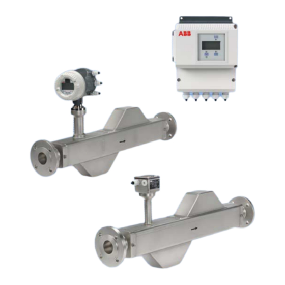
Mass Flowmeter
CoriolisMaster FCM2000
P R O F I
PROCESS FIELD BUS
B U S
®
Advertisement
Table of Contents

Related Manuals for ABB CoriolisMaster FCM2000


Summary of Contents for ABB CoriolisMaster FCM2000
- Page 1 Operating Instruction Mass Flowmeter D184B111U02 CoriolisMaster FCM2000 Pos: 1 /Titelblätter / Copyright/BA-IA/Durchfluss/FCM2000 @ 6\mod_1171653775140_3101.doc @ 67895 @ Standard Software D699G001U01 B.3x D699G001U02 A.1x D699G001U03 A.1x ® P R O F I PROCESS FIELD BUS B U S Pos: 2 /======= Seitenumbruch ======== @ 0\mod_1126532365768_3101.doc @ 3830 @...
-
Page 2: Abb Automation Products Gmbh Dransfelder Straße
Tel.: +49 551 905-534 Fax: +49 551 905-555 CCC-support.deapr@de.abb.com © Copyright 2008 by ABB Automation Products GmbH Subject to changes without notice This document is protected by copyright. It assists the user in safe and efficient operation of the device. -
Page 3: Table Of Contents
General information..........................23 4.1.2 Installation notes for FCM2000-MC2 ....................24 4.1.3 Installation notes FCM2000-MS2......................26 Installation ..............................28 4.2.1 General information on installation .......................28 4.2.2 Pressure relief valve..........................29 Display / housing rotation ..........................30 4.3.1 Housing rotation ............................30 4.3.2 Display rotation .............................31 D184B111U02 CoriolisMaster FCM2000... - Page 4 5.3.2 Output Circuits ............................54 5.3.3 NAMUR Contact............................55 5.3.4 Isolation: MC26.., MC27........................57 Information for safe operation – FM ......................58 5.4.1 Inspection ..............................58 5.4.2 Classes per FM .............................59 Parameterization..............................60 Data entry..............................60 Entering data in “short form”.........................62 Parameter overview .............................63 CoriolisMaster FCM2000 D184B111U02...
- Page 5 Material Loads Curves Flanged Flowmeters ..................105 10.2 Model FCM2000-MS2 ..........................106 10.3 Transmitter ..............................108 11 Appendix ................................109 11.1 Additional documents ..........................109 11.2 Approvals and certifications ........................109 11.3 Overview of setting parameters and technical design ................124 12 Index .................................126 D184B111U02 CoriolisMaster FCM2000...
-
Page 6: Safety
Read and follow the instructions in this manual. • Observe the technical ratings; refer to the section “Technical limit values”. Use only allowed liquids for measurement; refer to the section “Allowed fluids”. • Pos: 5.6 /======= Seitenumbruch ======== @ 0\mod_1126532365768_3101.doc @ 3830 @ CoriolisMaster FCM2000 D184B111U02... -
Page 7: Improper Use
Pos: 5.8 /Sicherheit/Allgemein/Hinweis zur bestimmungswidrigren Verwendung (Wartung/Reparatur) @ 0\mod_1129707002440_3101.doc @ 3240 @ Repairs, alterations, and enhancements, or the installation of replacement parts, are only permissible insofar as these are described in the manual. Approval by ABB Automation Products GmbH must be sought for any activities beyond this scope. Repairs performed by ABB-authorized specialist shops are excluded from this. -
Page 8: Allowed Fluids
Using the device in a manner that does not fall within the scope of its intended use, disregarding this manual, using underqualified personnel, or making unauthorized alterations releases the manufacturer from liability for any resulting damage. This renders the manufacturer's warranty null and void. Pos: 5.13 /======= Seitenumbruch ======== @ 0\mod_1126532365768_3101.doc @ 3830 @ CoriolisMaster FCM2000 D184B111U02... -
Page 9: Plates And Symbols
This symbol indicates operator tips, particularly useful information, or important information about the product or its further uses. It does not indicate a dangerous or damaging situation. Pos: 5.17 /======= Seitenumbruch ======== @ 0\mod_1126532365768_3101.doc @ 3830 @ D184B111U02 CoriolisMaster FCM2000... -
Page 10: Name Plate / Factory Tag
40.375 Cal.: V: +/-0.4 % D: +/- 5 g/l Qmax DN: 100 kg/min Tmed: -50 °C…+180 °C ABB Automation Products GmbH 37070 Göttingen – Germany G00352 Fig. 1 1 Order number 7 Meter pipe material 2 Complete model number 8 Calibration factor... - Page 11 1.4571 72.753 Cal.: F: +/-0.15% D: +/- 5 g/l Qmax DN: 920 kg/min TAG no.: FT–402 ABB Automation Products GmbH 37070 Göttingen – Germany G00353 Fig. 2 1 ATEX approval 6 Meter size and protection class 2 ATEX temperature classes...
- Page 12 S.-Nr.: 0012345 0045 DN 50 / PN 40 Material: 1.4571 Manufactured: 2002 PED: Fluid 1, Gas ABB Automation Products GmbH 37070 Göttingen - Germany G00410 Fig. 4 The factory plate contains the following information: 1 CE mark (with number of labeled location) to confirm the device meets the requirements of pressure equipment directive 97/23/EC.
-
Page 13: Target Groups And Qualifications
Prior to using corrosive and abrasive materials for measurement purposes, the operator must check the level of resistance of all parts coming into contact with the materials to be measured. ABB Automation Products GmbH will gladly support you in selecting the materials, but cannot accept any liability in doing so. -
Page 14: Disposal
If it is not possible to dispose of old equipment properly, ABB Service can accept and dispose of returns for a fee. Pos: 5.29 /Sicherheit/Durchfluss/FCM2000/Sicherheitshinweise zum Transport (Durchfluss) @ 7\mod_1174894735718_3101.doc @ 74253 @ 2 1.12 Safety instructions for transport... -
Page 15: Operating Safety Information
The purpose of these screws is to allow for proper disposal of any contaminated fluids (in the event of pipe leakage). Inspections screws may not be used under any circumstances to connect trace heating. D184B111U02 CoriolisMaster FCM2000... - Page 16 − the leak tightness − the wear (corrosion) Pos: 5.35 /Sicherheit/Durchfluss/FCM2000/Hinweis Befestigungsschrauben (Zeichnung) @ 11\mod_1176983310593_3101.doc @ 84454 @ G00391 Fig. 6 1 Mounting screws 2 Tower 3 Inspection screws Pos: 6 /======= Seitenumbruch ======== @ 0\mod_1126532365768_3101.doc @ 3830 @ CoriolisMaster FCM2000 D184B111U02...
-
Page 17: Design And Function
Pos: 8 /Aufbau und Funktion/Durchfluss/FCM2000/Aufbau @ 6\mod_1171654750218_3101.doc @ 68021 @ 2 Design The ABB Automation Products Mass Flowmeter operation is based on the Coriolis principle. The MC2 construction uses the classical parallel meter pipes and is characterized, in particular, by a space saving and rugged design, a wide flowmeter size spectrum at an advantageous price to the customer. - Page 18 Simplified Representation of the Coriolis Forces ω × = -2 m ( = Coriolis force ω = Angular velocity ν = Velocity of the mass m = Mass Pos: 10 /======= Seitenumbruch ======== @ 0\mod_1126532365768_3101.doc @ 3830 @ CoriolisMaster FCM2000 D184B111U02...
-
Page 19: Device Designs
Self-monitoring, diagnostics On-site display/totalization Field optimized flow/density Protection class acc. to EN ME2: IP 65 / 67, NEMA 4X 60529 MC _ _ : IP 67, NEMA 4X Pos: 13 /======= Seitenumbruch ======== @ 0\mod_1126532365768_3101.doc @ 3830 @ D184B111U02 CoriolisMaster FCM2000... -
Page 20: Model Overview Atex
Compact design: MC23 (A / T) Compact design: MC27B DN 1,5 ... DN 6 (1/10 ... 1/4") G00757 Flowmeter sensor: MS2 Transmitter: ME21 (A / T) Abb. 9: FCM2000 overview Pos: 16 /======= Seitenumbruch ======== @ 0\mod_1126532365768_3101.doc @ 3830 @ CoriolisMaster FCM2000 D184B111U02... -
Page 21: Model Overview Fm, Csa
Class I, Div. 1 Class I, Div. 2 General purpose / Area, Zone 1 Area, Zone 2 Safe Area MC23T ME21T MC27C MC23O MC21T ME21T ME21O MC21O G00332 Abb. 10 Pos: 19 /======= Seitenumbruch ======== @ 0\mod_1126532365768_3101.doc @ 3830 @ D184B111U02 CoriolisMaster FCM2000... -
Page 22: Transport
G00360 Fig. 11: Transport protection of nominal size “U” (DN 6, 1/4”) 1 Transport protection screw 2 Nipple and gasket Pos: 21 /======= Seitenumbruch ======== @ 0\mod_1126532365768_3101.doc @ 3830 @ CoriolisMaster FCM2000 D184B111U02... -
Page 23: Installation
The mass meter does not require any flow conditioning inlet straight G00361 sections. Care should be exercised to ensure that any valves, gates, Fig. 12: Vibrations sight glasses, etc., do not cavitate and are not set into vibration by the flowmeter sensor. D184B111U02 CoriolisMaster FCM2000... -
Page 24: Installation Notes For Fcm2000-Mc2
Horizontal Installation Orientations G00311 Fig. 13: Zero point adjustment with bypass line G00303 Fig. 15: Horizontal Installation Orientations Pos: 24.5 /======= Spaltenumbruch ======== @ 0\mod_1132937966324_3101.doc @ 3831 @ Pos: 24.9 /======= Spaltenumbruch ======== @ 0\mod_1132937966324_3101.doc @ 3831 @ CoriolisMaster FCM2000 D184B111U02... - Page 25 Pos: 24.14 /======= Spaltenumbruch ======== @ 0\mod_1132937966324_3101.doc @ 3831 @ G00305 Fig. 17: Installation in a Drop Line Supply reservoir Flowmeter sensor Orifice/pipe constriction Valve Product reservoir Pos: 24.12 /======= Spaltenumbruch ======== @ 0\mod_1132937966324_3101.doc @ 3831 @ D184B111U02 CoriolisMaster FCM2000...
-
Page 26: Installation Notes Fcm2000-Ms2
The multi-connection plug can be rotated within the angle noted. ± 5° ± 5° G00373 Fig. 22: Angle multi-connection plug – horizontal Pos: 24.20 /======= Spaltenumbruch ======== @ 0\mod_1132937966324_3101.doc @ 3831 @ CoriolisMaster FCM2000 D184B111U02... - Page 27 Pos: 24.22 /Technische Daten / Datenblatt/Durchfluss/FCM2000/Einbaubedingungen/MS2/Einbaulage DN 3 / DN 6 @ 11\mod_1168439375312_3101.doc @ 57839 @ 5 Vertical G00310 Fig. 24 Pos: 25 /==== Wechsel zwei- auf einspaltig ==== @ 0\mod_1130421955859_3101.doc @ 3829 @ Change from one to two columns Pos: 26 /======= Seitenumbruch ======== @ 0\mod_1126532365768_3101.doc @ 3830 @ D184B111U02 CoriolisMaster FCM2000...
-
Page 28: Installation
Tighten the cover fittings. • Install the separate transmitter at a largely vibration-free location. • Do not expose the transmitter to direct sunlight. Provide appropriate sun protection as necessary. Pos: 28.3 /======= Seitenumbruch ======== @ 0\mod_1126532365768_3101.doc @ 3830 @ CoriolisMaster FCM2000 D184B111U02... -
Page 29: Pressure Relief Valve
3. Ensure that the pressure relief valve is correctly installed and properly tightened, so the gasket is seated correctly. Whenever it is removed the gaskets should be replaced. G00370 Fig. 25 Connecting nipple Connecting nipple Pos: 28.5 /======= Seitenumbruch ======== @ 0\mod_1126532365768_3101.doc @ 3830 @ D184B111U02 CoriolisMaster FCM2000... -
Page 30: Display / Housing Rotation
Loosen the mounting screw (approx. 2 turns) Rotate converter to desired orientation Tighten the mounting screws G00381 Fig. 26: Rotating the Converter Housing Important After positioning the converter it is essential that a head set screws are tightened. CoriolisMaster FCM2000 D184B111U02... -
Page 31: Display Rotation
4. Check that the gasket is seated properly. 5. Carefully reinstall the housing cover in the new position. Only then will Protection Class IP 67 (NEMA 4X) be maintained. Pos: 28.7 /======= Seitenumbruch ======== @ 0\mod_1126532365768_3101.doc @ 3830 @ D184B111U02 CoriolisMaster FCM2000... -
Page 32: Installation Of The Field-Mount Housing / Compact Unit
Cable gland M20 x 1.5 Dimensions for installation Fig. 28: Dimensions, Converter Housing 1) Installation holes for pipe mounting set for a 2" pipe installation. Mounting set upon request. Pos: 28.13 /======= Seitenumbruch ======== @ 0\mod_1126532365768_3101.doc @ 3830 @ CoriolisMaster FCM2000 D184B111U02... -
Page 33: Connection Area For Compact Unit
4 Cover for the supply power. For supply power connections, see Fig. 41 Important Please lay the cable shield of the signal cable under the collecting bracket in the connection area! Pos: 28.15 /======= Seitenumbruch ======== @ 0\mod_1126532365768_3101.doc @ 3830 @ D184B111U02 CoriolisMaster FCM2000... -
Page 34: Connection Head Ms2
Tighten the four screws with a 4 mm hexagon socket wrench to secure the adapter. Install the multi-plug connector and tighten the screws on the plug to ensure proper seal. G00412 Pos: 29 /======= Seitenumbruch ======== @ 0\mod_1126532365768_3101.doc @ 3830 @ CoriolisMaster FCM2000 D184B111U02... -
Page 35: Electrical Connection
• Inductance: ca. 1 mH/km • Max. cable length: 50 m (164 ft.) Cut to length and terminate the cable as shown. Important Use wire end sleeves. 80 (0,59) 65 (2,56) (0,59) 8 (0,31) G00396 Fig. 30 D184B111U02 CoriolisMaster FCM2000... -
Page 36: Positioning The Shield Drain Wire And Foil Shield
2. Cut the woven shield to a length of approx. 15 mm (0.59”). 3. Remove cable drain wire and foil shield. 4. Remove cable insulation and attach cable conductor sleeves. 5. Wind shield core around woven shield. CoriolisMaster FCM2000 D184B111U02... - Page 37 G00413 Fig. 33 1 Make sure during installation that the cable is provided with a water trap (1). For vertical installation, align the cable glands pointing downward. Pos: 31.2 /======= Seitenumbruch ======== @ 0\mod_1126532365768_3101.doc @ 3830 @ D184B111U02 CoriolisMaster FCM2000...
-
Page 38: Interconnection Examples For Peripherals
Fig. 36: Contact input for external totalizer reset and external zero return Pulse Output active passive, optocoupler + 16 ... 30 V DC 24 V+ G00246 G00247 Fig. 37: Pulse output active and pulse output passive, optocoupler CoriolisMaster FCM2000 D184B111U02... - Page 39 (Front view showing pin insert and pins) PIN 1 = PA+ PIN 2 = nc PIN 3 = PA- PIN 4 = shield G00328 Fig. 39: Connection example via M12 plug Pos: 31.3.2 /======= Seitenumbruch ======== @ 0\mod_1126532365768_3101.doc @ 3830 @ D184B111U02 CoriolisMaster FCM2000...
-
Page 40: Connection Diagrams For Transmitter To Flowmeter Sensor
Gray / pink 85 / 86 Sensor 1 White 87 / 88 Sensor 2 Brown Green Yellow Gray Pink Black 10 Violet 11 Blue 12 Red 13 Functional ground Pos: 31.3.5 /======= Seitenumbruch ======== @ 0\mod_1126532365768_3101.doc @ 3830 @ CoriolisMaster FCM2000 D184B111U02... -
Page 41: Connection Diagrams For Transmitter To Peripherals
≤ 600 Ω) Functional ground Source voltage 12 ≤ U ≤ 30 V 4a pulse output passive, terminals: 51, 52 5 kHz, pulse width 0.1 … 2000 ms Pos: 31.3.8 /======= Seitenumbruch ======== @ 0\mod_1126532365768_3101.doc @ 3830 @ D184B111U02 CoriolisMaster FCM2000... - Page 42 ≤ 600 Ω) Functional ground Source voltage 12 ≤ U ≤ 30 V 4a pulse output passive, terminals: 51, 52 5 kHz, pulse width 0.1 … 2000 ms Pos: 31.3.10 /======= Seitenumbruch ======== @ 0\mod_1126532365768_3101.doc @ 3830 @ CoriolisMaster FCM2000 D184B111U02...
- Page 43 I = 14 mA (normal operation) I = 26 mA (in the event of error/FDE) Terminals: 97 / 98 Connection example via M12 plug, see Fig. 39 Pos: 31.4 /======= Seitenumbruch ======== @ 0\mod_1126532365768_3101.doc @ 3830 @ D184B111U02 CoriolisMaster FCM2000...
-
Page 44: Explosion Protection Data
If the ground wire (PE) in connection box of flowmeter is connected it has to be assured that no dangerous potential difference between the ground PE and potential balance can show up in the explosion hazardous area. Pos: 31.7.4 /======= Seitenumbruch ======== @ 0\mod_1126532365768_3101.doc @ 3830 @ CoriolisMaster FCM2000 D184B111U02... -
Page 45: Isolation: Mc26
Class I, Div. 1 Class I, Div. 2 General purpose / Area, Zone 1 Area, Zone 2 Safe Area MC23T ME21T MC27C MC23O MC21T ME21T ME21O MC21O G00332 Abb. 45 Pos: 31.7.7 /======= Seitenumbruch ======== @ 0\mod_1126532365768_3101.doc @ 3830 @ D184B111U02 CoriolisMaster FCM2000... -
Page 46: Ex-Approval Atex, Mc26B, Mc27B
(122 °F) Ex-Approval FM, MC21O, MC23O Nonincendive Class I,II, III, Division 2, Groups A, B, C, D, F, G/T6 T a = 60 °C (140 °F), NEMA 4X. Pos: 32 /======= Seitenumbruch ======== @ 0\mod_1126532365768_3101.doc @ 3830 @ CoriolisMaster FCM2000 D184B111U02... -
Page 47: Digital Communication
For additional information, see the separate data link description. 1.2 (DSV401 R2), respectively. Other desired tool/system inte- grations (e.g., AMS or Siemens S7) are available upon request. DSV401 communication tool for HART, free 90-day test version also available upon request. DTMs are included in DSV401. D184B111U02 CoriolisMaster FCM2000... -
Page 48: Foundation Fieldbus (Ff)
ABB at no cost. connection The files needed for operation can also be downloaded at www.abb.com/flow -> Coriolis Massflow -> Fieldbus Files Bus topology Pos: 36 /==== Wechsel zwei- auf einspaltig ==== @ 0\mod_1130421955859_3101.doc @ 3829 @ •... -
Page 49: Commissioning
If the data is not identical, the transmitter data is replaced automatically. Once completed, the message "Ext.Dat.loaded" is displayed. The measuring equipment is now ready for operation. The display shows the current flowrate. Pos: 38.5 /======= Seitenumbruch ======== @ 0\mod_1126532365768_3101.doc @ 3830 @ D184B111U02 CoriolisMaster FCM2000... -
Page 50: Device Configuration
“automatic” and select ENTER to start the adjustment. You can choose between slow or fast adjustment. Slow adjustment generally provides a more accurate zero point. Important All parameters are stored automatically in the FRAM Pos: 38.7 /======= Seitenumbruch ======== @ 0\mod_1126532365768_3101.doc @ 3830 @ CoriolisMaster FCM2000 D184B111U02... -
Page 51: Preliminary Checks Prior To Start-Up
Switch 9 and A have no significance for the address setting. Example: Address 50 set by switch: 50 dec = 32 hex = 110010 binary → Switch 2, 5, 6 and 8 1 2 3 4 5 6 7 8 9 A G00363 Fig. 50 D184B111U02 CoriolisMaster FCM2000... -
Page 52: Pulse Output, Change Active/Passive
Plug-in jumper location G00364 Fig. 51: Converter module G00365 G00366 Plug-in jumper position for passive pulse Plug-in jumper position for active pulse output output Fig. 52: Plug-in jumper position Pos: 38.12 /======= Seitenumbruch ======== @ 0\mod_1126532365768_3101.doc @ 3830 @ CoriolisMaster FCM2000 D184B111U02... -
Page 53: Operating Protection Switch
“Error – operating protection” and the input will be rejected. It is also possible to use a cover locking screw with a hole to seal the compact unit so that parameter changes cannot remain undetected. Pos: 38.15 /======= Seitenumbruch ======== @ 0\mod_1126532365768_3101.doc @ 3830 @ D184B111U02 CoriolisMaster FCM2000... -
Page 54: Information For Safe Operation - Atex
If the signal outputs are to be connected to intrinsically safe circuits, it is recommended that the included light blue caps be used for the corresponding cable connectors. Pos: 38.21 /======= Seitenumbruch ======== @ 0\mod_1126532365768_3101.doc @ 3830 @ CoriolisMaster FCM2000 D184B111U02... -
Page 55: Namur Contact
(Fig. 54). See also chapter Interconnection Diagrams. Plug-in jumper position Standard configuration NAMUR configuration preferred for Ex „e“ preferred for Ex „i“ (Default configuration) G00368 Fig. 54: Plug-in jumper positions Pos: 38.24 /======= Seitenumbruch ======== @ 0\mod_1126532365768_3101.doc @ 3830 @ D184B111U02 CoriolisMaster FCM2000... - Page 56 “intrinsically safe” or “non-intrinsically safe”. A combination is not permitted. The test voltage for the output circuits for both Types of Protecton is U = 60 V. Pos: 38.27 /======= Seitenumbruch ======== @ 0\mod_1126532365768_3101.doc @ 3830 @ CoriolisMaster FCM2000 D184B111U02...
-
Page 57: Isolation: Mc26
The pipeline and the flowmeter sensor insulation should be installed as shown. The max. insulation thickness at the flowmeter sensor is 100 mm (4“). G00331 Fig. 57 max. 100 mm (4“) Pos: 38.30 /======= Seitenumbruch ======== @ 0\mod_1126532365768_3101.doc @ 3830 @ D184B111U02 CoriolisMaster FCM2000... -
Page 58: Information For Safe Operation - Fm
• The connections between the flowmeter sensor and transmitter may only be made with the cable supplied by ABB Automation Products. • For safe operation it is essential to follow the instructions in this Operating instruction. •... -
Page 59: Classes Per Fm
Div 1, 2 Zone 2, 22 Zone 2, 22 Type 4X, IP 67/68 4X, IP 67 (MC210) 4X, IP 68 (MC230, ME210) Approval-Project ID: 301 52 61 Pos: 39 /======= Seitenumbruch ======== @ 0\mod_1126532365768_3101.doc @ 3830 @ D184B111U02 CoriolisMaster FCM2000... -
Page 60: Parameterization
Access the parameter to be changed and set the new, selected or default parameter. The ENTER function is only active for 10 seconds. If no entries are made during this period, the old value is displayed on the converter. CoriolisMaster FCM2000 D184B111U02... - Page 61 There are two different methods of entering data: • Numerical input • Entry from specified table Important When entering data, the values are checked for plausibility and, if necessary, rejected with an appropriate message. Pos: 41.2 /======= Seitenumbruch ======== @ 0\mod_1126532365768_3101.doc @ 3830 @ D184B111U02 CoriolisMaster FCM2000...
-
Page 62: Entering Data In "Short Form
STEP or DATA "Progr. level" or meter size Technician ENTER "Progr. level" blocked End point for "process information" C/CE → V 98.14 % (converter remains online). →V 12,000 m Pos: 41.4 /======= Seitenumbruch ======== @ 0\mod_1126532365768_3101.doc @ 3830 @ CoriolisMaster FCM2000 D184B111U02... -
Page 63: Parameter Overview
"Technician":"Technician":Expanded standard menus with the complete set of user specific parameters "Service":Additional set of Service menus only available to ABB Automation Products Service personnel. If the Prog. Prot.-Code is set to 0 (default setting) the programming levels "Standard" or "Technician" can be accessed without entering a code number. - Page 64 Note DensiMass code If ordered with DensiMass option, this menu shows the order specific DensiMass code. If the 4289794 DensiMass shall be activated after shipping the meter, please contact your ABB service or sales organisation. DensiMass Code invalid Submenu Concentration...
- Page 65 Calculated values are marked with a "C". Rules for valid values see 6.4.3. Matrix calculation Calculation of matrix based on above entered values. Missing values are inter- or extrapolated. Enter matrix Store or discard of above values. finish D184B111U02 CoriolisMaster FCM2000...
- Page 66 Unit name 3 ASCII ASCII In this menu the name or abbreviation of the programmable mass flow unit can be entered. The Technician* name can have a maximum of 3 characters. Not contained in the fieldbus software versions. CoriolisMaster FCM2000 D184B111U02...
- Page 67 This menu displays the maximum mass flowrate for the selected instrument size. 100.00 kg/min Order no. 16 ASCII Display Display of the Order Number. It is also listed on the Name Plate and on the label on the external 240012345X004 characters memory module. D184B111U02 CoriolisMaster FCM2000...
- Page 68 The concentration accuracy can be optimized in the field to come close to the repproducibilty of the 0.00 % Technician meter. The correction value has to be entered in the selected unit. C correction tab. 2 0.00 % CoriolisMaster FCM2000 D184B111U02...
- Page 69 The Max-Alarm value must be larger that the associated Min-Alarm value. Min Alarm Qm 0 ... 105 % float Set the lower mass flowrate limit. It must be less than the upper mass flowrate limit. 0.00 % Technician* Minimum: Maximum: 105 % D184B111U02 CoriolisMaster FCM2000...
- Page 70 Lower concentration limit must be lower than the Max alarm limit. 0.00 % Technician Max Alarm Concentr. -5 % ... 105.0 % The max alarm concentration limit must be bigger than the Min alarm limit. 0.00 % Technician CoriolisMaster FCM2000 D184B111U02...
- Page 71 TAG Number Totalizer Mass Totalizer Mass → F Totalizer Mass ← R Totalizer Volumes Totalizer Vol. → F Totalizer Vol. ← R Totalizer Net Mass Total. Net Mass → F Total. Net Mass ← R Pipe frequency Blank D184B111U02 CoriolisMaster FCM2000...
- Page 72 TAG Number Totalizer Mass Totalizer Mass → F Totalizer Mass ← R Totalizer Volumes Totalizer Vol. → F Totalizer Vol. ← R Totalizer Net Mass Total. Net Mass → F Total. Net Mass ← R Pipe frequency Blank CoriolisMaster FCM2000 D184B111U02...
- Page 73 Display of totalizer status for reverse direction; displayed in the Forward/Reverse operating mode 123456.78 l Input Overflow ← R Display Number of totalizer overflows Max. of 65535 overflows 1 overflow = 10000000; displayed in the Forward/Reverse operating mode D184B111U02 CoriolisMaster FCM2000...
- Page 74 Reset totalizer values, all flow totalizers are simultaneously reset to zero. The sequential Reset ? display of each totalizer is shown to certify that all Yes → ENTER totalizers have been reset. CoriolisMaster FCM2000 D184B111U02...
- Page 75 Submenu Not contained in the fieldbus software versions. Current output 1 Output float The selections in this menu are used to defined for which variable current output 1 is to be based. Density Temperature Concentration Qm Concentration D184B111U02 CoriolisMaster FCM2000...
- Page 76 100 % must be at least 10 °C larger than the temperature value for a current output value of 0 %. Qm% → l = 100 % Only displayed for "Output of Qn Conc." Net massflow at current output 100 %. 120 kg/min CoriolisMaster FCM2000 D184B111U02...
- Page 77 The setting for the alarm current 21 mA Technician* is independent of the current output range selected since all range end values are 20 mA. The High-Alarm-Current can be set between the limits of 21 mA and 26 mA. D184B111U02 CoriolisMaster FCM2000...
- Page 78 Minimum: -50 °C Maximum: 180 °C The temperature value for a current output value of 100 % must be at least 10 °C larger than the temperature value for a current output value of 0 %. CoriolisMaster FCM2000 D184B111U02...
- Page 79 2 can be selected. • Ext. zero return (Current and pulse outputs are set to 0% flowrate. Internal totalizers are halted.) • Totalizer reset. (resets all mass and volume flow totalizers) Not contained in the fieldbus software versions. D184B111U02 CoriolisMaster FCM2000...
- Page 80 (Packed ASCII). Descriptor 16 ASCII HART descriptor 123456789ABCDE The length is limited to 16 numbers and/or capital letters (Packed ASCII). Date 1.1.1900 ... HART file 07.07.2001 31.12.2155 Unit number 0 ... 999999 Display 1234567 CoriolisMaster FCM2000 D184B111U02...
- Page 81 TB TotVol > V • Temperature TB TotVol < R • Internal mass totalizer (in contrast to the PA TB Volume Flow totalizer) • Internal volume totalizer (in contrast to the PA totalizer) Only contained in the PROFIBUS PA software. D184B111U02 CoriolisMaster FCM2000...
- Page 82 TB Mass Flow can be assigned to the TOT 1 channel, and TB Volume Flow to the TOT 2 TB Volume Flow channel. These PROFIBUS PA totalizers can deviate from the FCM2000 internal totalizers. Only contained in the PROFIBUS PA software. CoriolisMaster FCM2000 D184B111U02...
- Page 83 A current between 0 ... 26 mA can be simulated. (In version A.00 the entry is made in percent) Iout 1 Not contained in the fieldbus software. 10 mA D184B111U02 CoriolisMaster FCM2000...
- Page 84 Simulated values for the variables can be entered which exceed the alarm limits to test the operation of the alarms. The settings in the simulation menu are not stored. After a power interruption all simulation menus are turned off. CoriolisMaster FCM2000 D184B111U02...
- Page 85 Temp. housing Measure float 20 °C Enter Enter Technician* Function test Technician* The two HART-Frequencies (1200 Hz and 2200 Hz) can be selected and transmitted. HART Transmitter Function test Technician* The received HART commands are displayed. HART command D184B111U02 CoriolisMaster FCM2000...
- Page 86 Example Display Ext. Cut-off Power outage Display the number of power outages since the last reset. Status The error and warning registers as well as the mains interrupt counter can be reset. Reset Reset Yes → ENTER CoriolisMaster FCM2000 D184B111U02...
- Page 87 (B.30) are displayed. In addition to the software identification in the operator menu, the identification can also be found on the information tag on the converter module. Pos: 41.7 /======= Seitenumbruch ======== @ 0\mod_1126532365768_3101.doc @ 3830 @ D184B111U02 CoriolisMaster FCM2000...
-
Page 88: Additional Parameter Descriptions
Display of Totalizer Net Massflow according to net-massflow Totalizer Net Mass → F Display of Totalizer Net Massflow - Forward Totalizer Net Mass ← R Display of Totalizer Net Massflow - Reverse Display the frequency of the meter pipe Pipe frequency Blank line CoriolisMaster FCM2000 D184B111U02... - Page 89 Display of the respective state of the Transducer Block FB TOT2 Out Display of the respective PA totalizer value within Function Block FB TOT2 Status Display of the respective state of the Transducer Block only in Technician menu D184B111U02 CoriolisMaster FCM2000...
-
Page 90: Submenu Pulse Output
0.2 ms (5 kHz) → maximum pulse width = Period /2 = 0.1 ms → Result: The entered pulse factor and pulse width were both automatically decreased Pos: 41.10 /======= Seitenumbruch ======== @ 0\mod_1126532365768_3101.doc @ 3830 @ CoriolisMaster FCM2000 D184B111U02... -
Page 91: Concentration Measurement Densimass
Concentr. 1 <…< Concentr. x < … < Concentr. N for 1 ≤ x ≤ N Concentr. 1 >…> Concentr. x > … > Concentr. N for 1 ≤ x ≤ N D184B111U02 CoriolisMaster FCM2000... - Page 92 60 °BRIX 1.101 kg / l 1.018 kg / l 1.011 kg / l The unit of density and temperature corresponds to the chosen units in submenu units. Pos: 41.13 /======= Seitenumbruch ======== @ 0\mod_1126532365768_3101.doc @ 3830 @ CoriolisMaster FCM2000 D184B111U02...
-
Page 93: Software History
Parameterization Pos: 41.14 /Konfiguration, Parametrierung/Durchfluss/FCM2000/Software-Historie @ 7\mod_1171894144875_3101.doc @ 69131 @ Software history According to NAMUR recommendation NE53, ABB offers a transparent and traceable software history. 6.5.1 Standard and HART version Software D699G001U01 Software Revision date Type of changes Documentation Version A.1x... -
Page 94: Fieldbus Version
Important Please note that the new 8 kB FRAM external storage medium can only be read as of software version A40 (or A10 of the fieldbus software)! Pos: 42 /======= Seitenumbruch ======== @ 0\mod_1126532365768_3101.doc @ 3830 @ CoriolisMaster FCM2000 D184B111U02... -
Page 95: Error Messages
0% and the current output, which signals the density, would be set to Low-Alarm regardless of the settings in the current output menu. Pos: 44.2 /======= Seitenumbruch ======== @ 0\mod_1126532365768_3101.doc @ 3830 @ D184B111U02 CoriolisMaster FCM2000... - Page 96 27 11b Sensor B − − − − Alarm Alarm Alarm − Alarm Alarm Alarm 28 11c Sensor C − − − − Alarm Alarm Alarm − Alarm Alarm Alarm Pos: 44.4 /======= Seitenumbruch ======== @ 0\mod_1126532365768_3101.doc @ 3830 @ CoriolisMaster FCM2000 D184B111U02...
-
Page 97: Description Of The Warnings
Flowrate is in the reverse direction Operating mode set to forward, In Submenu „Operating mode” actual flowrate is in reverse change flow direction to Reverse Q Forward/Reverse Pos: 44.7 /======= Seitenumbruch ======== @ 0\mod_1126532365768_3101.doc @ 3830 @ D184B111U02 CoriolisMaster FCM2000... -
Page 98: Description Of Error Messages
Pt 100 is defective Check the resistance of PT100 on of the measurement variable Qm the primary flowmeter a density of 20°C is used, i.e. for a fluid temperature near 20 °C the measurements will be correct CoriolisMaster FCM2000 D184B111U02... - Page 99 Concentration given and chosen matrix Error Parameters cannot be changed The operating protection switch is Deactivate the hardware active protection switch. prot. user trans Pos: 45 /======= Seitenumbruch ======== @ 0\mod_1126532365768_3101.doc @ 3830 @ D184B111U02 CoriolisMaster FCM2000...
-
Page 100: Maintenance / Repair
For repairs to the lining, electrodes or magnet coil, the flowmeter must be returned to the local office of ABB. Important When sending the flowmeter sensor to the local office of ABB, complete the return form in the appendix and include with device. Pos: 46.5 /======= Seitenumbruch ======== @ 0\mod_1126532365768_3101.doc @ 3830 @... -
Page 101: Cleaning
Warning – Electrical voltage risk! When the housing is open, EMC protection is impaired and protection against contact is suspended. • Power to all connecting cables must be switched off. Pos: 47 /======= Seitenumbruch ======== @ 0\mod_1126532365768_3101.doc @ 3830 @ D184B111U02 CoriolisMaster FCM2000... -
Page 102: Spare Parts List
Cover small (rear view) Fig. 60: Replaceable parts list transmitter field-mount housing Name Order number Transmitter module Please contact your ABB service team. Connection board standard D685A1020U10 Cover large, complete D641A030U01 Pan head Phillips screw M 3x5 DIN 7985 stn stl... - Page 103 Spare parts list G00385 Fig. 61: Fuse in field-mount housing 1 Fuse field-mount housing G00386 Fig. 62: Fuse in transmitter module 1 Fuse in module Pos: 50 /======= Seitenumbruch ======== @ 0\mod_1126532365768_3101.doc @ 3830 @ D184B111U02 CoriolisMaster FCM2000...
-
Page 104: Technical Data
± 0.4% of measured value ± 0.05 % of Q ± 0.25% of measured value ± 0.05 % of Q ± 0.15% of measured value ± 0.05 % of Q ± 0.1% of measured value ± 0.05 % of Q CoriolisMaster FCM2000 D184B111U02... -
Page 105: Materials And Additional Technical Data
1 mPa s Viscosity range Max. dyn. viscosity: ≤ 1 Pas (= 1000 mPas = 1000 cP) at higher viscosities, please contact our ABB representative. Pos: 53.3 /======= Seitenumbruch ======== @ 0\mod_1126532365768_3101.doc @ 3830 @ D184B111U02 CoriolisMaster FCM2000... -
Page 106: Model Fcm2000-Ms2
Reference conditions Calibration fluid Water 25 °C (77 °F) (+ 5 K / - 5 K) Pressure 0.5 ... 6 bar (7.3 ... 87.0 psi) Ambient temperature 25 °C (77 °F) (+ 10 K / - 5 K) CoriolisMaster FCM2000 D184B111U02... - Page 107 Pressure losses MS21, DN 1.5 (1/16”) Fig. 70: Pressure losses MS21, DN 6 (1/4”) Viscosity [cSt] Pos: 53.6 /======= Seitenumbruch ======== @ 0\mod_1126532365768_3101.doc @ 3830 @ 300 [kg/h] G00318 Fig. 69: Pressure losses MS21, DN 3 (1/10”) D184B111U02 CoriolisMaster FCM2000...
-
Page 108: Transmitter
(EN 61326) as well as low voltage directive 73/23/EC (EN 61010-1). Pos: 54 /==== Wechsel zwei- auf einspaltig ==== @ 0\mod_1130421955859_3101.doc @ 3829 @ Change from one to two columns Pos: 55 /======= Seitenumbruch ======== @ 0\mod_1126532365768_3101.doc @ 3830 @ CoriolisMaster FCM2000 D184B111U02... -
Page 109: Appendix
FM Approvals (US) Pos: 56.6 /Hinweise/Wichtig/Wichtig - Verweis auf Download-Bereich @ 21\mod_1215086830219_3101.doc @ 204693 @ Important All documentation, declarations of conformity, and certificates are available in ABB's download area. www.abb.com/flow Pos: 56.7 /======= Seitenumbruch ======== @ 0\mod_1126532365768_3101.doc @ 3830 @... - Page 110 Appendix Pos: 56.8 /Zertifikate/Durchfluss/FCM2000/EG-Konformitätserklärung @ 24\mod_1227010300386_0.doc @ 227237 @ CoriolisMaster FCM2000 D184B111U02...
- Page 111 Appendix Pos: 56.9 /Zertifikate/Durchfluss/FCM2000/EG-Baumusterprüfbescheinigung_ATEX_1443_X @ 24\mod_1227011659745_3101.doc @ 227261 @ D184B111U02 CoriolisMaster FCM2000...
- Page 112 Appendix CoriolisMaster FCM2000 D184B111U02...
- Page 113 Appendix D184B111U02 CoriolisMaster FCM2000...
- Page 114 Appendix CoriolisMaster FCM2000 D184B111U02...
- Page 115 Appendix D184B111U02 CoriolisMaster FCM2000...
- Page 116 Appendix CoriolisMaster FCM2000 D184B111U02...
- Page 117 Appendix D184B111U02 CoriolisMaster FCM2000...
- Page 118 Appendix CoriolisMaster FCM2000 D184B111U02...
- Page 119 Appendix D184B111U02 CoriolisMaster FCM2000...
- Page 120 Appendix CoriolisMaster FCM2000 D184B111U02...
- Page 121 Appendix Pos: 56.10 /Zertifikate/Durchfluss/FCM2000/EG-Konformitätserklärung_DGRL @ 24\mod_1227012045777_0.doc @ 227285 @ D184B111U02 CoriolisMaster FCM2000...
- Page 122 Appendix Pos: 56.11 /Zertifikate/Durchfluss/FCM2000/EHEDG-Zertifikat @ 24\mod_1227012151464_0.doc @ 227309 @ CoriolisMaster FCM2000 D184B111U02...
- Page 123 Appendix Pos: 56.12 /======= Seitenumbruch ======== @ 0\mod_1126532365768_3101.doc @ 3830 @ D184B111U02 CoriolisMaster FCM2000...
-
Page 124: Overview Of Setting Parameters And Technical Design
....0.5 ... 3.5 kg/l alarm, F/R-Signal Communication HART: ....HART, off HART Instrument ....0 ... 15 Address: Contact input/output: Communication: HART protocol Pulse output: Active Passive Limit alarm Pos: 56.14 /======= Seitenumbruch ======== @ 0\mod_1126532365768_3101.doc @ 3830 @ CoriolisMaster FCM2000 D184B111U02... - Page 125 Which substances have come into contact with the device? We hereby state that the devices/components shipped have been cleaned and are free from any dangerous or poisonous substances. Town/city, date Signature and company stamp Pos: 57 /======= Seitenumbruch ======== @ 0\mod_1126532365768_3101.doc @ 3830 @ D184B111U02 CoriolisMaster FCM2000...
-
Page 126: Index
Pressure loss curves..........107 Exchanging the transmitter ......49, 101 Pressure relief valve ..........29 Explosion protection data ........44 Repairs, alterations, and enhancements ....7 Factory plate ............12 Representation of the Coriolis Forces .....18 Factory Tag..............10 Returning devices ............13 Flowmeter sensor ..........100 CoriolisMaster FCM2000 D184B111U02... - Page 127 WEEE Directive ............14 Target groups and qualifications......13 Pos: 61 /==== Wechsel zwei- auf einspaltig ==== @ 0\mod_1130421955859_3101.doc @ 3829 @ Change from one to two columns Pos: 62 /Rückseiten/Göttingen @ 0\mod_1138784575421_3101.doc @ 3125 @ ===== Ende der Stückliste ===== D184B111U02 CoriolisMaster FCM2000...
- Page 128 ABB has Sales & Customer Support expertise in over The Company’s policy is one of continuous product 100 countries worldwide. improvement and the right is reserved to modify the information contained herein without notice. www.abb.com/flow Printed in the Fed. Rep. of Germany (12.2008) ©...
Need help?
Do you have a question about the CoriolisMaster FCM2000 and is the answer not in the manual?
Questions and answers