Table of Contents
Advertisement
Quick Links
—
A BB MEA SU RE ME NT & A NA L YT I C S | O PE R A TI N G I NS T RU C T I O N | OI / FC D 4 0 0 -EN RE V . A
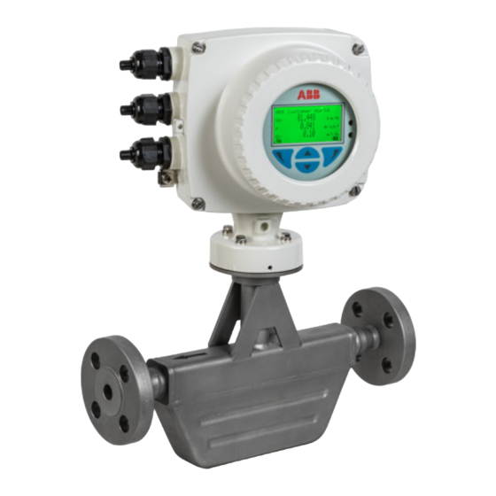
CoriolisMaster FCD400
Coriolis mass flowmeter
—
Introduction
CoriolisMaster FCD450
With no up or downstream piping requirements
the compact Coriolis flowmeters can be installed
in the tightest spaces, enabling applications not
possible before.
CoriolisMaster FCD400
The compact Coriolis mass flow meters of the
CoriolisMaster FCD400 series offer a low
pressure drop, high capacity, an intuitive ABB
display with a standardized design across all
products, five modular inputs and outputs and
various communication options such as HART®
Modbus®, PROFIBUS®, Ethernet/IP® and
PROFINET®.
Device firmware version: 01.11.00
Measurement made easy
Additional Information
Additional documentation on CoriolisMaster FCD400
is available for download free of charge at
www.abb.com/flow.
Alternatively simply scan this code:
Advertisement
Table of Contents

Related Manuals for ABB CoriolisMaster FCD400


Summary of Contents for ABB CoriolisMaster FCD400
- Page 1 Alternatively simply scan this code: CoriolisMaster FCD400 The compact Coriolis mass flow meters of the CoriolisMaster FCD400 series offer a low pressure drop, high capacity, an intuitive ABB display with a standardized design across all products, five modular inputs and outputs and various communication options such as HART®...
-
Page 2: Table Of Contents
FCD400 CORIOLIS MASS FLOWMETER | OI/FCD400-EN REV. A Table of contents Design and function ..........29 Safety ................ 5 General .................29 General information and instructions ....... 5 Measuring principle ............29 Warnings ................5 Device designs ..............30 Intended use ................. 6 Improper use ................ - Page 3 Terminal assignment ............51 Parameterization of the device ......... 78 Electrical data for inputs and outputs ......52 Installation of the ABB Field Information Manager Power supply L / N, 1+ / 2−..........52 (FIM)................. 79 Requirements for inputs and outputs ......52 Parameterization via the infrared service port adapter Current output 32 / Uco, 31 / 32 (basic device) ...52...
- Page 4 FCD400 CORIOLIS MASS FLOWMETER | OI/FCD400-EN REV. A 11 Diagnosis / error messages ........ 155 Calling up the error description........155 General ................155 Overview ................156 Error messages ..............158 12 Maintenance ............162 Safety instructions ............162 Sensor ................162 Repairs to the flowmeter ..........
-
Page 5: Safety
FCD400 CORIOLIS MASS FLOWMETER | OI/FCD400-EN REV. A 1 Safety Warnings General information and instructions The warnings in these instructions are structured as follows: These instructions are an important part of the product and must be retained for future reference. DANGER Installation, commissioning, and maintenance of the product may only be performed by trained specialist personnel who have... -
Page 6: Intended Use
ABB and its affiliates are not liable for damages and/or losses related to such security breaches, any unauthorized access, When using measuring media, the following points must be... -
Page 7: Warranty Provisions
This renders the manufacturer's warranty null and void. Manufacturer’s address ABB AG Measurement & Analytics Schillerstr. 72 32425 Minden Germany... -
Page 8: Use In Potentially Explosive Atmospheres
FCD400 CORIOLIS MASS FLOWMETER | OI/FCD400-EN REV. A 2 Use in potentially explosive atmospheres Note Further information on the Ex-Approval of devices can be found in the type examination certificates or the relevant certificates at www.abb.com/flow Device overview ATEX, IECEx and UKEX Standard / No explosion protection... -
Page 9: Cfmus
FCD400 CORIOLIS MASS FLOWMETER | OI/FCD400-EN REV. A cFMus Standard / No explosion protection Class I Div. 2 / Zone 2 Class I Div. 1 / Zone 1 (Zone 0) Model number FCx4xx Y0 FCx4xx F2 FCx4xx F1 Integral mount design •... -
Page 10: Ex Marking
FCD400 CORIOLIS MASS FLOWMETER | OI/FCD400-EN REV. A … 2 Use in potentially explosive atmospheres Ex marking Description of model numbers Each device design has a specific model number. The parts of the model number relating to explosion protection are listed in the following table. - Page 11 FCD400 CORIOLIS MASS FLOWMETER | OI/FCD400-EN REV. A Basic model FCa4c Connection Design / Transmitter Housing Type / Transmitter Housing Type / Cable Glands Integral mount / dual-compartment housing / aluminum / 3 × M20 × 1.5 Integral mount / dual-compartment housing / aluminum / 3 × NPT ½ in Integral mount / dual-compartment housing / aluminum / 3 ×...
- Page 12 FCD400 CORIOLIS MASS FLOWMETER | OI/FCD400-EN REV. A … 2 Use in potentially explosive atmospheres … Ex marking Additional ordering information FCa4cdefghijklm Option card 1 2 port Ethernet (various protocols) DR6* 1 × active digital output Option card 2 Power over Ethernet module / Modbus DS8* 1 ×...
-
Page 13: Atex, Iecex And Ukex
Note • A specific marking applies, depending on the design. • ABB reserves the right to modify the Ex-marking. Refer to the name plate for the exact marking. Model number for use in Zone 2, 21 Ex marking Certificate FCa4c – A2Y0fghijD; FCa4c – U2Y0fghijD II3G Ex ec IIC T6...T1 Gc... - Page 14 Note • A specific marking applies, depending on the design. • ABB reserves the right to modify the Ex-marking. Refer to the name plate for the exact marking. Model number for use in Division 2 Ex marking Certificate: FM18US0160X Certificate: FM18CA0073X FCa4c –...
-
Page 15: Temperature Data
FCD400 CORIOLIS MASS FLOWMETER | OI/FCD400-EN REV. A Temperature data Sensor in remote mount design Temperature resistance for the connecting cable The temperature at the cable entries of the device depends on the design, the measuring medium temperature T and the medium ambient temperature T amb. -
Page 16: Measuring Medium Temperature For Sensors In Integral Mount Design With Dual-Compartment Housing
FCD400 CORIOLIS MASS FLOWMETER | OI/FCD400-EN REV. A Po s : 1 1 .3 3 / M o d u l e / … 2 Use in potentially explosive atmospheres … Temperature data Measuring medium temperature for sensors in integral mount design with dual-compartment housing Model FCx4xx-A1…, Model FCx4xx-U1…... -
Page 17: Measuring Medium Temperature For Sensors In Integral Mount Design With Single-Compartment Housing
FCD400 CORIOLIS MASS FLOWMETER | OI/FCD400-EN REV. A Measuring medium temperature for sensors in integral mount design with single-compartment housing Model FCx4xx-A2…, Model FCx4xx-U2… and FCx4xx-F2… in Zone 2, Division 2 The table shows the maximum permissible measuring medium temperature as a function of ambient temperature and temperature class. -
Page 18: Measuring Medium Temperature For Sensors In Remote Mount Design
FCD400 CORIOLIS MASS FLOWMETER | OI/FCD400-EN REV. A … 2 Use in potentially explosive atmospheres … Temperature data Measuring medium temperature for sensors in remote mount design Model FCx4xx-A1…, Model FCx4xx-U1… and FCx4xx-F1… in Zone 1 The table shows the maximum permissible measuring medium temperature as a function of ambient temperature and temperature class. -
Page 19: Electrical Data
FCD400 CORIOLIS MASS FLOWMETER | OI/FCD400-EN REV. A Electrical data Overview Zones 2, 21 Zone 1, 21 (Zone 0) Division 2 and Zone 2, 21 Division 1 and Zone 1, 21 ATEX: ATEX / UKEX: ATEX / UKEX: – II 3 G & II 2 D II 1/2 (1) G &... -
Page 20: Zone 2, 21 And Division 2 - Model: Fcx4Xx-A2
FCD400 CORIOLIS MASS FLOWMETER | OI/FCD400-EN REV. A … 2 Use in potentially explosive atmospheres … Electrical data Zone 2, 21 and Division 2 – Model: FCx4xx-A2…, FCx4xx-U2… and FCx4xx-F2… Outputs on basic device Operating values (general) Type of protection – ‘nA’ / ‘NI’ Current / HART output 31 / U , active 30 V... - Page 21 FCD400 CORIOLIS MASS FLOWMETER | OI/FCD400-EN REV. A Inputs and outputs with optional plug-in cards Operating values (general) Type of protection – ‘nA’ / ‘NI’ Current output V3 / V4, active* 30 V 30 mA 30 V 30 mA Terminals V3 / V4 and V1 / V2* Current output V1 / V2, passive** 30 V 30 mA...
-
Page 22: Zone 1 ,21 And Division 1 - Model: Fcx4Xx-A1
FCD400 CORIOLIS MASS FLOWMETER | OI/FCD400-EN REV. A … 2 Use in potentially explosive atmospheres … Electrical data Zone 1 ,21 and Division 1 – Model: FCx4xx-A1…, FCx4xx-U1… and FCx4xx-F1… Type of protection ‘e’ / ‘XP’ ‘ia’ / ‘IS’ Outputs on basic device [mA] [mA] [mW]... - Page 23 FCD400 CORIOLIS MASS FLOWMETER | OI/FCD400-EN REV. A Type of protection ‘e’ / ‘XP’ ‘ia’ / ‘IS’ Inputs and outputs with optional plug-in cards [mA] [mA] [mW] [mW] [nF] [nF] [nF] [nF] [mH] [mH] Current output V3 / V4, active* 27.8 Terminals V3 / V4 and V1 / V2* Current output V1 / V2, passive**...
-
Page 24: Special Connection Conditions
FCD400 CORIOLIS MASS FLOWMETER | OI/FCD400-EN REV. A … 2 Use in potentially explosive atmospheres … Electrical data Special connection conditions Note Devices connected to the relevant equipment must not be The AS plug-in card (24 V DC loop power supply) may only be operated at over 250 V AC or 250 V DC to ground. -
Page 25: Installation Instructions
Only original spare parts must be used to seal the housing. by appropriately trained personnel. The operator must strictly observe the applicable national Note regulations with regard to installation, function tests, repairs, Spare parts can be ordered from ABB Service. and maintenance of electrical devices. (e. g. NEC, CEC). www.abb.com/contacts... -
Page 26: Cable Entries In Accordance With Atex/Iecex And Ukex
FCD400 CORIOLIS MASS FLOWMETER | OI/FCD400-EN REV. A … 2 Use in potentially explosive atmospheres … Installation instructions Cable entries in accordance with cFMus Cable entries in accordance with ATEX/IECEx and UKEX The devices are supplied with cable glands installed (certified in accordance with ATEX or IECEx). -
Page 27: Specific Conditions Of Use
FCD400 CORIOLIS MASS FLOWMETER | OI/FCD400-EN REV. A Specific Conditions of Use Electrical connections Note WARNING The temperature at the cable entries of the device depends on Special conditions for safe use! the design, the measuring medium temperature T and the medium •... -
Page 28: Process Sealing
• The painted surface of the device is thereby relatively free from impurities such as dirt, dust or oil. ABB flowmeters are designed for the worldwide industrial • Instructions on avoiding ignition in potentially explosive market and are suitable for functions such as the measurement... -
Page 29: Design And Function
FCD400 CORIOLIS MASS FLOWMETER | OI/FCD400-EN REV. A 3 Design and function General Function for calculating Coriolis force The ABB CoriolisMaster operates according to the Coriolis principle. ω − × The construction features conventional parallel meter tubes and is characterized in particular by its space-saving, sturdy design, ... -
Page 30: Device Designs
Remote mount design: IP 65 / IP 67 / IP 68 (sensor only, immersion depth: 5 m), NEMA 4X Approvals • Explosion protection ATEX / IECEx / NEPSI / cFMus — • Hygiene approvals • Further approvals www.abb.com/flow or upon request. Indication of accuracy in % of the measured value... - Page 31 FCD400 CORIOLIS MASS FLOWMETER | OI/FCD400-EN REV. A 1 Dual-compartment housing 2 Single-compartment housing Figure 5: Transmitter with remote mount design Transmitter Integral mount design (see Figure 4, pos. 1 and 2), Chassis remote mount design (see Figure 5, pos. 1 and 2). IP rating IP 65 / IP 67, NEMA 4X Cable length...
-
Page 32: Product Identification
FCD400 CORIOLIS MASS FLOWMETER | OI/FCD400-EN REV. A Po s : 2 6 /Mo d u l e /Üb e rsc h r i fte n / 1 /P - R/ P ro 4 Product identification Name plate Al l Note The marking is provided on the name plate and on the sensor The name plates displayed are examples. -
Page 33: Transport And Storage
FCD400 CORIOLIS MASS FLOWMETER | OI/FCD400-EN REV. A 5 Transport and storage Inspection Check the devices immediately after unpacking for possible damage that may have occurred from improper transport. Details of any damage that has occurred in transit must be recorded on the transport documents. -
Page 34: Storing The Device
Calculating pressure loss Pressure loss depends on the properties of the medium and the flow rate. A good aid for pressure loss calculation is the Online ABB Product Selection Assistant (PSA) for flow at www.abb.com/flow-selector. -
Page 35: Installation Position / Installation Conditions
FCD400 CORIOLIS MASS FLOWMETER | OI/FCD400-EN REV. A Liquid measuring media Brackets and supports Observe the following points to avoid measuring errors: In systems designed in accordance with ‘Best Practice’, the • The meter tubes must always be completely filled with forces acting on the device are already sufficiently absorbed. -
Page 36: Gaseous Measuring Media
FCD400 CORIOLIS MASS FLOWMETER | OI/FCD400-EN REV. A … 6 Installation … Installation position / installation conditions Gaseous measuring media For vertical installation in a riser, no special measures are required. Observe the following points to avoid measuring errors: For vertical installation in a downpipe, a piping constriction •... -
Page 37: Turn-Off Devices For The Zero Point Adjustment
FCD400 CORIOLIS MASS FLOWMETER | OI/FCD400-EN REV. A Turn-off devices for the zero point adjustment Sensor insulation 1 Insulation Figure 13: Installation at T −50°to 220 °C (−58 to 428 °F) medium The sensor must only be insulated in conjunction with the TE3 ‘Extended tower length for sensor insulation’... -
Page 38: Process Conditions
Temperature limits °C (°F) You can reference the availability of the different process Note connections in the Online ABB Product Selection Assistant (PSA) When using the device in potentially explosive atmospheres, for flow www.abb.com/flow-selector. note the additional temperature data in Temperature data on •... -
Page 39: Installing The Sensor
FCD400 CORIOLIS MASS FLOWMETER | OI/FCD400-EN REV. A Installing the sensor Before installation in the piping, observe the installation conditions and instructions on the mounting position! 1. Insert the sensor into the piping centrally and positioned coplanar. Use suitable gaskets to seal the process connections. - Page 40 FCD400 CORIOLIS MASS FLOWMETER | OI/FCD400-EN REV. A … 6 Installation … Installing the transmitter in the remote mount design 1 Hole pattern for mounting holes 1 Hole pattern for mounting holes 2 Female thread (either ½ in NPT or M20 × 1.5), see model coding. In the 2 Female thread (either ½...
-
Page 41: Opening And Closing The Housing
FCD400 CORIOLIS MASS FLOWMETER | OI/FCD400-EN REV. A Opening and closing the housing Dual- compartment housing DANGER Danger of explosion if the device is operated with the transmitter housing or terminal box open! Before opening the transmitter housing or the terminal box, note the following points: •... -
Page 42: Single-Compartment Housing
FCD400 CORIOLIS MASS FLOWMETER | OI/FCD400-EN REV. A … 6 Installation Adjusting the transmitter position … Opening and closing the housing Single-compartment housing Depending on the installation position, the transmitter housing or LCD display can be rotated to enable horizontal readings. Transmitter housing DANGER Damaging the device carries a risk of explosion! -
Page 43: Rotate Lcd Indicator - Dual-Compartment Housing
FCD400 CORIOLIS MASS FLOWMETER | OI/FCD400-EN REV. A Rotate LCD indicator – dual-compartment housing Rotate LCD indicator – single-compartment housing The LCD indicator can be rotated in three increments of 90° each. Figure 26: Possible positions of LCD indicator The LCD indicator can be rotated to the positions. -
Page 44: Installing The Plug-In Cards
FCD400 CORIOLIS MASS FLOWMETER | OI/FCD400-EN REV. A … 6 Installation Installing the plug-in cards WARNING Loss of Ex Approval! Loss of Ex Approval due to retrofitting of plug-in cards on devices for use in potentially explosive atmospheres. • Devices for use in potentially explosive atmospheres may not be retrofitted with plug-in cards. •... - Page 45 The following table provides an overview of the possible plug-in card combinations that can be selected when ordering the device. Because of the wide variety of options, not all combinations can be presented. The possible combinations are shown in our online ABB Product Selection Assistant (PSA) for flow at www.abb.com/flow-selector. Main ordering...
-
Page 46: Dual-Compartment Housing
FCD400 CORIOLIS MASS FLOWMETER | OI/FCD400-EN REV. A Po s : 3 … 6 Installation … Installing the plug-in cards Dual-compartment housing 1 Cover 4 Slot OC2 2 LCD indicator 5 Slot OC1 3 Frontend board (FEB, with integral mount design only) 6 Plug-in cards Figure 28: Installation of plug-in cards (example, dual-compartment housing) WARNING... -
Page 47: Single-Compartment Housing
FCD400 CORIOLIS MASS FLOWMETER | OI/FCD400-EN REV. A Single-compartment housing 1 Cover 4 Slot OC2 2 LCD indicator 5 Plug-in cards 3 Slot OC1 Figure 29: Installation of plug-in cards (example, single-compartment housing) 1. Switch off the power supply. WARNING 2. -
Page 48: Ethernet Card
The electronic components of the printed circuit board can be For detailed instructions how to plug in and connect the Power damaged by static electricity (observe ESD guidelines). over Ethernet (PoE) card, please contact ABB. • Make sure that the static electricity in your body is... -
Page 49: Electrical Connections
FCD400 CORIOLIS MASS FLOWMETER | OI/FCD400-EN REV. A 7 Electrical connections Power supply Safety instructions Note WARNING • Adhere to the limit values of the power supply in accordance Risk of injury due to live parts. with the information on the name plate. Improper work on the electrical connections can result in •... -
Page 50: Installing The Connection Cables
(AWG 19) 200 m (656 ft) Recommended cables It is recommended to use an ABB signal cable for standard applications. The ABB signal cable fulfills the above-mentioned cable specification and can be utilized unrestrictedly up to an 1 Drip loop ambient temperature of T = 80 °C (176 °F). -
Page 51: Terminal Assignment
FCD400 CORIOLIS MASS FLOWMETER | OI/FCD400-EN REV. A Terminal assignment A Transmitter B Sensor Figure 32: Electrical connection Connections for the power supply Connections for inputs and outputs AC voltage Terminal Function / comments Terminal Function / comments Uco / 32 Current output 4 to 20 mA- / HART®... -
Page 52: Electrical Data For Inputs And Outputs
FCD400 CORIOLIS MASS FLOWMETER | OI/FCD400-EN REV. A … 7 Electrical connections Electrical data for inputs and outputs Note Current output 32 / Uco, 31 / 32 (basic device) When using the device in potentially explosive atmospheres, Can be configured for outputting mass flow, volume flow, note the additional temperature data in Use in potentially density and temperature via on-site software. -
Page 53: Current Output Uco / 32 As Loop Power Supply For Digital Output 41 / 42 Or 51 / 52
FCD400 CORIOLIS MASS FLOWMETER | OI/FCD400-EN REV. A Current output Uco / 32 as loop power supply for digital output 41 / 42 or 51 / 52 In the case of digital communication via Modbus / PROFIBUS DP, the current output Uco / 32 can be switched to the ‘Power Mode’ operating mode through the software. -
Page 54: Digital Output 41 / 42, 51 / 52 (Basic Device)
FCD400 CORIOLIS MASS FLOWMETER | OI/FCD400-EN REV. A … 7 Electrical connections … Electrical data for inputs and outputs Current output V1 / V2, V3 / V4 (plug-in module) Digital output 41 / 42, 51 / 52 (basic device) Up to two additional plug-in modules can be implemented via Can be configured as pulse, frequency or binary output via on- the ‘Passive current output (red)’... -
Page 55: Passive Digital Output V1 / V2, V3 / V4 (Plug-In Card)
FCD400 CORIOLIS MASS FLOWMETER | OI/FCD400-EN REV. A Passive digital output V1 / V2, V3 / V4 (plug-in card) Active digital output V1 / V2, V3 / V4 (plug-in card) An additional binary output can be implemented via the ‘Passive An additional binary output can be implemented via the ‘Active digital output (green)’... -
Page 56: Digital Input V1 / V2, V3 / V4 (Plug-In Module)
FCD400 CORIOLIS MASS FLOWMETER | OI/FCD400-EN REV. A … 7 Electrical connections … Electrical data for inputs and outputs Digital input V1 / V2, V3 / V4 (plug-in module) Dependency of the output voltage U from the load R Load R is the parallel connection of the internal resistance R A digital input can be implemented via the ‘Passive digital input and optional external resistance R... -
Page 57: Dc Loop Power Supply (Plug-In Card)
FCD400 CORIOLIS MASS FLOWMETER | OI/FCD400-EN REV. A 24 V DC loop power supply (plug-in card) Connection examples Use of the ‘loop power supply (blue)’ plug-in card allows a Input and output functions are configured via the device passive output on the transmitter to be used as an active software in accordance with the desired application. - Page 58 FCD400 CORIOLIS MASS FLOWMETER | OI/FCD400-EN REV. A … 7 Electrical connections … Electrical data for inputs and outputs Digital output 41 / 42, 51 / 52 passive on distributed control Current output V3 / V4 active system When the ‘loop power supply 24 V DC, blue’ plug-in card is used, the current output on the plug-in card can also be wired as the active current output.
- Page 59 FCD400 CORIOLIS MASS FLOWMETER | OI/FCD400-EN REV. A Connection versions digital output 41 / 42, 51 / 52 Depending on the wiring of digital outputs DO 41 / 42 and 51 / 52, they can be used parallel or only individually. The electrical isolation between the digital outputs also depends on the wiring.
-
Page 60: Connection On The Device
FCD400 CORIOLIS MASS FLOWMETER | OI/FCD400-EN REV. A … 7 Electrical connections Connection on the device Connection to integral mount design Dual- compartment housing Single-compartment housing 1 Terminals for power supply 5 LCD indicator 2 Cover for power supply terminals 6 Bracket for LCD indicator (park position) 3 Terminals for inputs and outputs 7 Terminal for protective earth / cable shields... - Page 61 FCD400 CORIOLIS MASS FLOWMETER | OI/FCD400-EN REV. A NOTICE If the O-ring gasket is seated incorrectly or damaged, this may have an adverse effect on the housing protection class. Follow the instructions in Opening and closing the housing on page 40 to open and close the housing safely. Observe the following points when connecting to an electrical supply: •...
-
Page 62: Connection To Remote Mount Design
FCD400 CORIOLIS MASS FLOWMETER | OI/FCD400-EN REV. A Po s : 4 … 7 Electrical connections … Connection on the device Connection to remote mount design Transmitter Dual- compartment housing A Upper terminal box (back side) 3 Terminals for signal cable B Lower terminal box 4 Terminals for inputs and outputs C Signal cable to sensor... - Page 63 40 to open and close the housing safely. connection area of the transmitter. • Connect the cables in accordance with the electrical Terminal ABB signal cable HELKAMA signal cable connection diagram. If present, connect the cable shielding 3KQZ407123U0100 20522 to the earthing clamp provided.
- Page 64 40 to open and close the housing safely. earthing clamp provided. • Use wire end ferrules when connecting. Terminal ABB signal cable HELKAMA signal cable • From an ambient temperature of T ≥ 60 °C (≥ 140 °F) amb.
-
Page 65: Digital Communication
PCS7) on request. communication bus, without the need for any special interface devices to be used. The necessary DTMs and other files can be downloaded from www.abb.com/flow. Modbus protocol Terminals V1 / V2 HART output... -
Page 66: Cable Specification
RS485 systems, a surge impedance of more than 100 Ω is www.profibus.com. preferred, especially at a baud rate of 19200 and above. ABB provides three different GSD files which can be integrated in the system. ID number GSD file name 0x9741 PA139741.gsd... -
Page 67: Ethernet/Ip™ And Profinet® Communication
RD− Orange at > 1500 kBit/s: LS = 0.00 m! Pin 3 White / Green • At 1500 kBit/s and ABB DP cable type A: Pin 4 TD− Green – Sum of all spur cable lengths (L ) ≤ 6.60 m, trunk cable... -
Page 68: Ethernet Communication
White / Green GSDML data GSDML-V2.42-ABB_001A-3436_FLOW_CORIOLIS- 20230127.xml Pin 4 TD− Green Device ID ABB 0x3436 (manufacturer-specific) or Pin 1 White / Orange PNO 0xB333 (PA Profile) Pin 2 RD− Orange Support standards and Common Industrial Protocol (CIP™) Vol1, Ed. 3.25... -
Page 69: Wiring With Different Network Topologies
FCD400 CORIOLIS MASS FLOWMETER | OI/FCD400-EN REV. A Wiring with different network topologies A Daisy chain C Star B Ring Figure 61: Network topologies Ethernet Option Cards are designed only for use in hazardous applications Zone 2 / Division 2 or general purpose areas. The output circuits are designed so that different topologies such as daisy chain or point to point can be connected. -
Page 70: Connect The Retractable Plug To The Ethernet Card
FCD400 CORIOLIS MASS FLOWMETER | OI/FCD400-EN REV. A … 8 Digital communication … EtherNet/IP™ and PROFINET® communication Topology Number of connected Number of wires in Port Terminal Function Cable Ethernet cables the Ethernet cable Ring or daisy chain White / Orange RD−... -
Page 71: Preparing The Ethernet Cat5E Cable
FCD400 CORIOLIS MASS FLOWMETER | OI/FCD400-EN REV. A Preparing the EtherNet Cat5e cable M12 connector (optional) A variety of options are available for the M12 connector through the model code: • Flowmeter equipped with 1 × M12 (four-wire, connection to Port 1) •... -
Page 72: Rj45 Connector (Optional)
FCD400 CORIOLIS MASS FLOWMETER | OI/FCD400-EN REV. A … 8 Digital communication … EtherNet/IP™ and PROFINET® communication Use in Potentially Explosive Atmospheres 1. Remove the sealing cap of the M12 metal connector on the WARNING transmitter housing when delivered. There are limitations to the M12 connector in combination 2. - Page 73 FCD400 CORIOLIS MASS FLOWMETER | OI/FCD400-EN REV. A Electrical connections You can reference the in the transmitter and the corresponding pin assignment in the RJ45 connector in the following table: Wiring inside the transmitter Color Ethernet plug-in card Port/pin RJ45 four-wire Yellow Port 1 X1 Orange...
-
Page 74: Ethernet Card Status Leds
FCD400 CORIOLIS MASS FLOWMETER | OI/FCD400-EN REV. A Po s : 4 4 .4 4 / M o d u l e /++ ++ +++ +++ ++Ab s a tz f o r m e r 3 p t++ +++ +++ +++ + @ 9 4 \ m o d _ 1 4 6 1 9 2 9 6 2 4 1 8 4 _ …... - Page 75 FCD400 CORIOLIS MASS FLOWMETER | OI/FCD400-EN REV. A PROFINET® communication Status HMI display Description A Port 1 Network connection (link up) No network B Activity 1 Flashing or ON Traffic No traffic C Port 2 Network connection (link up) No network D Activity 2 Flashing or ON Traffic...
-
Page 76: Commissioning
FCD400 CORIOLIS MASS FLOWMETER | OI/FCD400-EN REV. A 9 Commissioning Hardware settings Safety instructions DANGER Dual- compartment housing Explosion hazard Improper installation and commissioning of the device carries a risk of explosion. • For use in potentially explosive atmospheres, observe the information in Use in potentially explosive atmospheres on page 8! CAUTION... -
Page 77: Single-Compartment Housing
FCD400 CORIOLIS MASS FLOWMETER | OI/FCD400-EN REV. A Single-compartment housing Configuration of digital outputs V1 / V2 or V3 / V4 1 DIP switch, Write protection Figure 68: Position of the DIP switch The DIP switches are used to configure specific hardware functions. -
Page 78: Checks Prior To Commissioning
Not all tools and frame applications support DTMs or EDDs at the same level. In particular, optional or advanced EDD / DTM System Startup functions may not be available on all tools. ABB provides frame Processing applications supporting the full range of functions and performance. -
Page 79: Installation Of The Abb Field Information Manager (Fim)
Installation of the software and connection to the flowmeter: 1. Install ABB Field Information Manager (FIM). 2. Unpack the ABB FDI package into the c:\temp folder. 3. Connect the flowmeter with the PC / laptop, see chapter Parameterization via the infrared service port adapter on page 80 or Parameterization via HART®... -
Page 80: Parameterization Via The Infrared Service Port Adapter
PC / notebook and the FZA100 infrared service port By combining the HART DTM available at www.abb.com/flow adapter. and the ABB Field Information Manager (FIM) , all parameters can By combining the FDI package available at www.abb.com/flow also be set via the HART protocol. -
Page 81: Basic Setup
FCD400 CORIOLIS MASS FLOWMETER | OI/FCD400-EN REV. A Basic Setup The device can be factory parameterized to customer specifications upon request. If no customer information is available, the device is delivered with factory settings. Settings for the most common parameters are summarized in the ‘Easy Setup’ menu. This menu is the quickest way to perform the initial configuration of the device. - Page 82 FCD400 CORIOLIS MASS FLOWMETER | OI/FCD400-EN REV. A … 9 Commissioning … Basic Setup Menu / parameter Description Dig.Out 51 / 52 Mode Selection of the operating mode for the digital output 51 / 52. • Off: Digital output deactivated. •...
- Page 83 FCD400 CORIOLIS MASS FLOWMETER | OI/FCD400-EN REV. A Menu / parameter Description Easy Setup Dig.Out V1 / V2 Mode Selection of the operating mode for digital output V1 / V2. Digital output V1 / V2 is only available if the corresponding plug-in card is present! •...
- Page 84 FCD400 CORIOLIS MASS FLOWMETER | OI/FCD400-EN REV. A … 9 Commissioning … Basic Setup Menu / parameter Description DO 41/42 Freq. Selection of process value issued via the frequency or pulse output. Dig.Out 41/42 Pulse Only if digital output 41 / 42 has been configured as a frequency or pulse output. Available process variables on page 94 Dig.Out 51/52 Freq.
-
Page 85: 10 Operation
FCD400 CORIOLIS MASS FLOWMETER | OI/FCD400-EN REV. A 10 Operation Safety instructions The LCD indicator has capacitive operating buttons. These CAUTION enable you to control the device through the closed housing Risk of burns due to hot measuring media cover. The device surface temperature may exceed 70 °C (158 °F), depending on the measuring medium temperature! Note... -
Page 86: Menu Levels
FCD400 CORIOLIS MASS FLOWMETER | OI/FCD400-EN REV. A Po s : 7 4 .1 4 / M o d u l e /++ + … 10 Operation Menu levels Process display Information level Configuration level (Operator Menu) (Configuration) ...Operator Page 1 … 4 Easy Setup Autoscroll Device Info... -
Page 87: Process Display
FCD400 CORIOLIS MASS FLOWMETER | OI/FCD400-EN REV. A Process display Switching to the information level On the information level, the operator menu can be used to display diagnostic information and choose which operator pages to display. Process display 1 Measuring point tagging 3 ‘Button function’... -
Page 88: Error Messages On The Lcd Display
Standard All the parameters can be changed. Note Service Only ABB Customer Service has access to the Service For a detailed description of errors and troubleshooting menu. instructions, please see Diagnosis / error messages on page 155. - Page 89 7. Confirm the selection with RSTUVWXYZ 0123456 Back Select 4. Contact ABB Service and request a one-time password, stating the ‘ID’ and ‘Pin’ shown. 5. Enter the one-time password. Note The one-time password is only valid once and needs to separately requested with each password reset.
-
Page 90: Selecting And Changing Parameters
FCD400 CORIOLIS MASS FLOWMETER | OI/FCD400-EN REV. A … 10 Operation … Switching to the configuration level (parameterization) Selecting and changing parameters Parameter name Entry from table 12.3456 [unit] When an entry is made from a table, a value is selected from a list of parameter values. - Page 91 FCD400 CORIOLIS MASS FLOWMETER | OI/FCD400-EN REV. A Exiting the setup For some menu items, values must be entered. If you don't want to change the parameter, you can exit the menu as described below. 1. Pressing (Next) repeatedly moves the cursor to the right. Once the cursor reaches the end position, ‘Cancel’...
-
Page 92: Available Units
FCD400 CORIOLIS MASS FLOWMETER | OI/FCD400-EN REV. A … 10 Operation Available units For certain parameters it is possible to choose among the Table 2: Units for the mass flow rate following units. Selection Code Description Grams per second Note g/min Grams per minute The ‘Code’... - Page 93 FCD400 CORIOLIS MASS FLOWMETER | OI/FCD400-EN REV. A Table 5: Concentration units Table 9: Pulses per flow unit Selection Code Description Selection Code Description Concentration in % 1/kg Per kilogram Brix Brix concentration Per gram Variable The concentration is calculated with the variables 1/m³...
-
Page 94: Available Process Variables
FCD400 CORIOLIS MASS FLOWMETER | OI/FCD400-EN REV. A … 10 Operation Available process variables The process variables available in the software are listed in the table. Process variables can be assigned to the display (HMI), the current outputs (CO), the frequency outputs (DO [f]), and the pulse outputs (DO [pulse]). - Page 95 FCD400 CORIOLIS MASS FLOWMETER | OI/FCD400-EN REV. A Process variable Modbus Code Code [hex] Description HMI CO DO address PROFIBUS DP [pulse] Totalizer Qm ∑m+ 851 (double) 0x13 Mass flow counter reading in the forward flow direction — — — 259 (float) Totalizer Qm Rev ∑m- 855 (double)
- Page 96 FCD400 CORIOLIS MASS FLOWMETER | OI/FCD400-EN REV. A … 10 Operation … Available process variables Process variable Modbus Code Code [hex] Description HMI CO DO address PROFIBUS DP [pulse] Total. Net Qv ∑V+-S 923 (double) 0x2B Absolute value from net volume flow counter reading in forward flow —...
-
Page 97: Parameter Overview
FCD400 CORIOLIS MASS FLOWMETER | OI/FCD400-EN REV. A Parameter overview Note This overview of parameters shows all the menus and parameters available on the device. Depending on the version and configuration of the device, not all of the menus and parameters may be visible in it. Easy Setup Language Unit Massflow Qm... - Page 98 FCD400 CORIOLIS MASS FLOWMETER | OI/FCD400-EN REV. A … 10 Operation … Parameter overview Device Info ...Sensor Sensor Type Meter Size Feature Series ...Transmitter Qm Max DN Span Forward Span Reverse Zero Sensor Freq.@ Empty Pipe Density @ Empty Pipe Freq.@ Full Pipe Density @ Full Pipe Calibration Pressure...
- Page 99 FCD400 CORIOLIS MASS FLOWMETER | OI/FCD400-EN REV. A Device Setup ...Access Control Standard Password Read Only Switch ...Sensor Range Mode Config Qm Max DN Qm Max Qm Max 2 Qm Range Mode Qv Max DN Qv Max Qv Max 2 Qv Range Mode Density Max Density Min...
- Page 100 FCD400 CORIOLIS MASS FLOWMETER | OI/FCD400-EN REV. A … 10 Operation … Parameter overview ...Transmitter ...Units Unit Massflow Qm Unit Mass Totalizer Unit Volumeflow Qv ...Custom Units Unit Vol. Totalizer Unit Density Damping Qm Unit Temperature Damping Density Concentration Density Mode Variable 1 Name Density Fixed Value Variable 2 Name...
- Page 101 FCD400 CORIOLIS MASS FLOWMETER | OI/FCD400-EN REV. A ...Variable Matrix ...Configuration Number Matrices Number Temp. Matrix Name Number Conc. Unit Name Enter Conc. in % Concentration Min Qm/Qv Conc. Switch Concentration Max Reset Matrix Matrix 1 Unit See chapter Entering the Matrix 1 Percent concentration matrix on page 151 for further...
- Page 102 FCD400 CORIOLIS MASS FLOWMETER | OI/FCD400-EN REV. A … 10 Operation … Parameter overview Display Language Contrast ...Operator Pages ...Operator Page 1 Display Mode 1st Line 2nd Line Autoscroll ...Operator Page 2 3rd Line Mass Flow Format 4th Line Mass Format ...Operator Page 3 Bargraph Volume Flow Format...
- Page 103 FCD400 CORIOLIS MASS FLOWMETER | OI/FCD400-EN REV. A ...Dig.Out 51/52 Mode Outp. Flow Direction ...Setup Freq Output Output Value Freq. Upper Frequency Pulses per Unit ...Setup Logic Output ...Alarm Config Logic Output Action Active Mode General Alarm Qm Massflow Max Qm Massflow Min Density Max Density Min...
- Page 104 FCD400 CORIOLIS MASS FLOWMETER | OI/FCD400-EN REV. A … 10 Operation … Parameter overview Process Alarm Alarm history Clear Alarm History ...Group Masking Maintenance Required Function Check ...Alarm Limits Out Of Specification Qm Massflow Min Qm Massflow Max Qv Volumeflow Min Qv Volumeflow Max Density Min Density Max...
- Page 105 FCD400 CORIOLIS MASS FLOWMETER | OI/FCD400-EN REV. A Communication ...HART Device Address Loop Current Mode HART Tag ...Modbus HART Long Tag HART Descriptor ...Profibus HART Message HART Manuf. ID ...Ethernet HART Device ID HART Find Last HART Command PV Primary Variable SV Secondary Var.
- Page 106 FCD400 CORIOLIS MASS FLOWMETER | OI/FCD400-EN REV. A … 10 Operation … Parameter overview Access ...EtherNetIP* Device status ...PROFINET* Vendor ID Product/Device type Product name Product code Product major rev. Product minor rev. Access Device status Device Name Tag function Select Device Type SNMP access Access...
- Page 107 FCD400 CORIOLIS MASS FLOWMETER | OI/FCD400-EN REV. A Diagnostics ...Diagnosis Control Preset Maint. cycle Maint. Remain. Time ...Diagnosis Values Start New Cycle Driver Output Sensor Signal A Sensor Signal B Tube Frequency Pipe Temperature Sensor Housing Temp. Electr. (FEB) Temp Readback curr.
- Page 108 FCD400 CORIOLIS MASS FLOWMETER | OI/FCD400-EN REV. A … 10 Operation … Parameter overview Totalizer ...Operation Start all Totalizer Stop all Totalizer ...Reset Totalizer All Totalizer ...Preset Totalizer All Mass Totalizer All Volume Totalizer Massflow Fwd ...FillMass Massflow Rev Volumeflow Fwd Volumeflow Rev Net Massflow Fwd Net Massflow Rev...
-
Page 109: Parameter Descriptions
FCD400 CORIOLIS MASS FLOWMETER | OI/FCD400-EN REV. A Parameter descriptions Menu: Easy Setup Menu / parameter Description Easy Setup Language Selection of menu language. Unit Massflow Qm Selection of the unit for mass flow rate (for example for the Q Max / Q MaxDN parameters and for the corresponding process value). - Page 110 FCD400 CORIOLIS MASS FLOWMETER | OI/FCD400-EN REV. A … 10 Operation … Parameter descriptions Menu / parameter Description Dig.Out 51 / 52 Mode Selection of the operating mode for the digital output 51 / 52. • Off: Digital output deactivated. •...
- Page 111 FCD400 CORIOLIS MASS FLOWMETER | OI/FCD400-EN REV. A Menu / parameter Description Easy Setup Dig.Out V1 / V2 Mode Selection of the operating mode for digital output V1 / V2. Digital output V1 / V2 is only available if the corresponding plug-in card is present! •...
- Page 112 FCD400 CORIOLIS MASS FLOWMETER | OI/FCD400-EN REV. A … 10 Operation … Parameter descriptions Menu / parameter Description DO 41/42 Freq. Selection of process value issued via the frequency or pulse output. Dig.Out 41/42 Pulse Only if digital output 41 / 42 has been configured as a frequency or pulse output. Available process variables on page 94 Dig.Out 51/52 Freq.
-
Page 113: Menu: Device Info
FCD400 CORIOLIS MASS FLOWMETER | OI/FCD400-EN REV. A Menu: Device Info This menu is only used to display the device parameters. The parameters are displayed independently of the configured access level, but cannot be changed. Menu / parameter Description Device Info ...Sensor Selection of submenu ‘...Sensor’... - Page 114 FCD400 CORIOLIS MASS FLOWMETER | OI/FCD400-EN REV. A … 10 Operation … Parameter descriptions Menu / parameter Description Device Info / ...Transmitter DensiMass On / Off DensiMass function present? 0 - Off: No DensiMass function present. 1 - On: DensiMass function present. Batchflow On / Off FillMass function present? 0 - Off: No FillMass function present.
-
Page 115: Menu: Device Setup
FCD400 CORIOLIS MASS FLOWMETER | OI/FCD400-EN REV. A Menu: Device Setup Menu / parameter Description Device Setup ...Access Control Selection of submenu ‘...Access Control’ using ...Sensor Selection of submenu ‘...Sensor’ using ...Transmitter Selection of submenu ‘...Transmitter’ using ...System Zero Selection of submenu ‘...System Zero’ using ...Concentration Selection of submenu ‘...Concentration’... - Page 116 FCD400 CORIOLIS MASS FLOWMETER | OI/FCD400-EN REV. A … 10 Operation … Parameter descriptions Menu / parameter Description Device Setup / ...Sensor Qv Range Mode Manual switchover between the measuring ranges (Qv Max / Qv Max 2) for the volume flow measurement. This parameter is only available if the value Qm and Qv or Qv only has been selected for the parameter ‘Range Mode Config’.
- Page 117 FCD400 CORIOLIS MASS FLOWMETER | OI/FCD400-EN REV. A Menu / parameter Description Device Setup / ...Transmitter ...Units Selection of submenu ‘...Units’ using ...Custom Units Selection of submenu ‘...Custom Units’ using Damping Qm Sets the damping for measuring mass flow. The value set here relates to 1 τ (Tau). The value refers to the response time for a stepwise mass flow change.
- Page 118 FCD400 CORIOLIS MASS FLOWMETER | OI/FCD400-EN REV. A … 10 Operation … Parameter descriptions Menu / parameter Description Device Setup / ...Transmitter / ...Units Unit Massflow Qm Selection of unit for mass flow. Refer to Table 6: Units for the mass counter on page 93. The selection applies to the display of the current mass flow, and for the parameters related to mass flow such as QmMax and QmMaxDN.
- Page 119 Enter the device-specific code for activating the CoriolisControl function. After entering the code, restart the device (e.g. by setting the ‘Device Restart' parameter or by briefly switching off the power supply). To use this function subsequently, contact the ABB service team or sales organization. Menu / parameter Description Device Setup / ...System Zero...
- Page 120 FCD400 CORIOLIS MASS FLOWMETER | OI/FCD400-EN REV. A … 10 Operation … Parameter descriptions Menu / parameter Description Device Setup / ...Concentration The menu is only available if the DensiMass function is activated Medium Selection of measuring medium for concentration measurement using the DensiMass function. •...
- Page 121 FCD400 CORIOLIS MASS FLOWMETER | OI/FCD400-EN REV. A Menu / parameter Description Device Setup / ...Field Optimization Density Correction Sets the correction factor for field optimization of the density measurement. This factor can be used to perform optimization in the field in order to achieve a degree of accuracy in the density measurement that closely approximates a repeatability of 0.0001 g/ml.
- Page 122 The value is used to compensate for the influence of pressure on the measurement of the mass flow and the density. ABB uses a special compensation algorithm that takes various influencing effects into account. This allows the pressure influence on the vibrations of the meter tube to be compensated.
-
Page 123: Menu: Display
FCD400 CORIOLIS MASS FLOWMETER | OI/FCD400-EN REV. A Menu: Display Menu / parameter Description Display Language Selection of menu language. Available languages: English, Deutsch, Français, Español, Português, Italiano, Chinese Contrast Contrast setting for the LCD display..Operator Pages Selection of submenu ‘...Operator Pages’ using Up to four user-specific operator pages (layouts) can be configured for the process display. -
Page 124: Menu: Input/Output
FCD400 CORIOLIS MASS FLOWMETER | OI/FCD400-EN REV. A … 10 Operation … Parameter descriptions Menu: Input/Output Menu / parameter Description Input/Output ...Curr.Out 31 / 32 / Uco Selection of submenu ‘...Curr.Out 31 / 32 / Uco’ using ...Curr.Out V1/V2 Selection of submenu ‘...Curr.Out V1/V2’ using ...Curr.Out V3/V4 Selection of submenu ‘...Curr.Out V3/V4’... - Page 125 FCD400 CORIOLIS MASS FLOWMETER | OI/FCD400-EN REV. A Menu / parameter Description Input/Output / Curr.Out 31 / 32 / Uco Input/Output / Curr.Out V1/V2 Input/Output / Curr.Out V3/V4 Iout for Alarm Selection of status of the current output in error condition. The output ‘low' or ‘high’...
- Page 126 FCD400 CORIOLIS MASS FLOWMETER | OI/FCD400-EN REV. A … 10 Operation … Parameter descriptions Menu / parameter Description Input/Output / ...Dig.Out 41/42 / ..Setup Pulse Output Note The pulse output can be classically configured via the pulse value (‘Pulses per Unit’ parameter), alternatively you can also enter the pulse frequency at 100 % flow rate (‘Frequency @ Qmax’...
- Page 127 FCD400 CORIOLIS MASS FLOWMETER | OI/FCD400-EN REV. A Menu / parameter Description Input/Output / ...Dig.Out 41/42 / ...Setup Logic Output Logic Output Action Selection of binary output function. • F / R Signal: The binary output signals the flow direction. •...
- Page 128 FCD400 CORIOLIS MASS FLOWMETER | OI/FCD400-EN REV. A … 10 Operation … Parameter descriptions Menu / parameter Description Input/Output / ...Dig.Out 51/52 Mode Selection of the operating mode for the digital output 51 / 52. The operating modes ‘Follow DO 41/42, 90° Shift, 180° Shift’ are available only if the digital output 41 / 42 has been configured as a pulse or frequency output.
- Page 129 FCD400 CORIOLIS MASS FLOWMETER | OI/FCD400-EN REV. A Menu / parameter Description Input/Output / ...Dig.Out 51/52 ...Setup Freq Output Selection of submenu ‘...Setup Logic Output’ using Only available if ‘Mode’ Frequency has been selected..Setup Logic Output Selection of submenu ‘...Setup Logic Output’ using Only available if ‘Mode’...
- Page 130 FCD400 CORIOLIS MASS FLOWMETER | OI/FCD400-EN REV. A … 10 Operation … Parameter descriptions Menu / parameter Description Input/Output / ...Dig.Out V3/V4 Mode Selection of the operating mode for digital output V3 / V4. The operating modes ‘Follow DO 41/42, 90° Shift, 180° Shift’ are available only if the digital output 41 / 42 has been configured as a pulse or frequency output.
- Page 131 FCD400 CORIOLIS MASS FLOWMETER | OI/FCD400-EN REV. A Menu / parameter Description Input/Output / ...Dig.Out V3/V4 / ...Setup Freq Output Note The frequency output can be classically configured via the frequency for 100 % flow rate (‘Upper Frequency’ parameter), alternatively you can also enter the pulse value at 100 % flow rate (‘Pulses per Unit’...
- Page 132 FCD400 CORIOLIS MASS FLOWMETER | OI/FCD400-EN REV. A … 10 Operation … Parameter descriptions Input/Output / ...Dig.In V1/V2 Input/Output / ...Dig.In V3/V4 Function Select a function for the digital input. • Off: No function. • Reset all Totalizer: Totalizer reset for all totalizers (forward, reverse and differential totalizers) •...
-
Page 133: Menu: Process Alarm
FCD400 CORIOLIS MASS FLOWMETER | OI/FCD400-EN REV. A Menu: Process Alarm Menu / parameter Description Process Alarm Clear Alarm History Reset of the alarm history..Group Masking Selection of submenu ‘...Group Masking’ using ...Alarm Limits Selection of submenu ‘...Alarm Limits’ using Process Alarm / ...Group Masking Maintenance Required Alarm messages are divided into groups. -
Page 134: Menu: Communication
Alphanumeric, a maximum of 16 characters, upper case only, no special characters. HART Message Display of the alphanumeric TAG number. HART Manuf. ID Display of the HART manufacturer ID. ABB = 26 HART Device ID Display of the HART device ID. HART Find Select whether the transmitter must respond to the HART command 73 (Find Device). - Page 135 Ident Nr. Selector Display the PROFIBUS DP® identification number • 0x9741: 2×AI + 1×TOT • 0x9742: 3×AI + 1×TOT • 0x3434: ABB specific Comm State Display the PROFIBUS communication status. • Offline: No PROFIBUS® communication. • Stop: Bus active, device not active.
- Page 136 If you are dealing with a part of a subnet, the first block of numbers should identical with the HOST IP - for example, 192.168.001.xxx. NTPServer1 IP addr. Factory setting: 000,000,000,000 NTPServer2 IP addr. Factory setting: 000,000,000,000 Host name Factory setting: ABB-Flow-EMF Domain name Factory setting: my-domain DNS1 IP address automatically set at DHCP = ON: 000,000,000,000 DNS2 IP address Communication / ...Webserver...
- Page 137 Can only be written via PROFINET (e.g. I&M1) 32 x ASCI characters Select Device Type Selection of device profile • ABB 0x3436: Manufacturer-specific GSD (factory setting) • PA Profiles 0xB333: PNO Profile GSD SNMP access Activate / deactivate SNMP access.
- Page 138 FCD400 CORIOLIS MASS FLOWMETER | OI/FCD400-EN REV. A … 10 Operation … Parameter descriptions Communication / ...ModbusTCP Access Factory setting: full. • Disabled • read only • full IEEE Format Factory setting: Enabled. • Enabled • disabled Menu / parameter Description Communication / ...Data link layer Chasis MAC address...
-
Page 139: Menu: Diagnostics
FCD400 CORIOLIS MASS FLOWMETER | OI/FCD400-EN REV. A Menu: Diagnostics Menu / parameter Description Diagnostics ...Diagnosis Control Selection of submenu ‘...Diagnosis Control’ using ...Diagnosis Values Selection of submenu ‘...Diagnosis Values’ using ...Drag Indicators Selection of submenu ‘...Drag Indicators’ using ...Simulation Mode Selection of submenu ‘...Simulation Mode’... - Page 140 FCD400 CORIOLIS MASS FLOWMETER | OI/FCD400-EN REV. A … 10 Operation … Parameter descriptions Menu / parameter Description Diagnostics / ...Drag Indicators / ...Sensor Indicators Driver Output Max Display of the maximum transmitter driver current since the last reset of the drag indicators. Sensor Amp.
- Page 141 FCD400 CORIOLIS MASS FLOWMETER | OI/FCD400-EN REV. A Menu / parameter Description Diagnostics / ...Output Readings Curr.Out 31 / 32 / Uco Display the current values and statuses of the listed inputs and outputs. Curr.Out V1/V2* Curr.Out V3/V4* DO 41/42 Freq. DO 41/42 State Dig.Out 51/52 Freq.
- Page 142 FCD400 CORIOLIS MASS FLOWMETER | OI/FCD400-EN REV. A … 10 Operation … Parameter descriptions Menu / parameter Description Diagnostics / ...Diag.CurrOut 31/32 Readback curr. 31/32 Activate the monitoring function for current output 31 / 32. The transmitter measures the actual current and compares the measured value to the set point for the current output. If the measured value deviates from the set point by more than ±2 %, the current output on the alarm current of 3.3 mA is set and the ‘CO 31/32 readbackcurrent deviates’...
-
Page 143: Menu: Totalizer
FCD400 CORIOLIS MASS FLOWMETER | OI/FCD400-EN REV. A Menu: Totalizer Menu / parameter Description Totalizer ...Operation Selection of submenu ‘...Operation’ using ...Reset Totalizer Selection of submenu ‘...Reset Totalizer’ using ...Preset Totalizer Selection of submenu ‘...Preset Totalizer’ using ...FillMass Selection of submenu ‘...FillMass’ using Totalizer / ...Operation Start all Totalizer Starts all counters. - Page 144 FCD400 CORIOLIS MASS FLOWMETER | OI/FCD400-EN REV. A … 10 Operation … Parameter descriptions Menu / parameter Description Totalizer / ...FillMass Batch Process Value Selection of process variable used during the filling process. The process variables ‘Net Volumeflow Fwd’ and ‘Net Massflow Fwd’ are only available when the DensiMass function is activated.
-
Page 145: Software History
FCD400 CORIOLIS MASS FLOWMETER | OI/FCD400-EN REV. A Software history In accordance with NAMUR recommendation NE53, ABB offers a transparent and traceable software history. Device software package FCx4xx (Device Firmware Package) Version Issue date Type of change Description Ordering number 00.01.00... -
Page 146: Measurement Of Standard Volumes
FCD400 CORIOLIS MASS FLOWMETER | OI/FCD400-EN REV. A … 10 Operation Measurement of standard volumes Coriolis mass flowmeters can only measure the mass flow of gaseous measuring media. The operating density of gases is too low to be measured. Consequently the flowmeter is also unable to measure the operating volume. - Page 147 FCD400 CORIOLIS MASS FLOWMETER | OI/FCD400-EN REV. A Configuration of the standard volume measurement using the HART DTM Example Calculation of standard cubic meters per day (sm Measured medium Natural gas Density in standard conditions 0.7168 kg/m Measuring range 0 ... 10000 sm A Set the parameter ‘Unit Volume Qv’...
-
Page 148: Verimass Erosion Monitor
‘Control Type’ to ‘Auto’. monitor can be adjusted manually. 3. In the ‘Diagnostics / ...Meter Erosion Mon.’ menu, set the For more information, please contact ABB Service or the sales parameter ‘Self Adjust Time’ to the required duration of organization. -
Page 149: Enhanced Coriolis Control (Ecc)Function
Enhanced Coriolis Control (ECC)function The Enhanced Coriolis Control (ECC)function has been specially Manual adjustment via the transmitter menu developed for demanding applications, such as: For more information, please contact ABB Service or the sales • Liquids with gas phase organization. -
Page 150: Applications In Accordance With Api (American Petroleum Institute)
CoriolisMaster FCD400 provides special parameters: The following concentration matrices are preconfigured in the • Calibration Pressure: Measuring medium pressure at transmitter as standard: which the device was calibrated at ABB. • Concentration of sodium hydroxide in water • Calibration Temp.: Measuring medium temperature at •... -
Page 151: Accuracy Of The Concentration Measurement
However, as the calculation is based on temperature and density 1. The desired ABB matrix is indicated when ordering the (the input variables), the accuracy of the concentration device. The device is then delivered with the measurement is ultimately determined by the measuring corresponding preconfiguration. - Page 152 FCD400 CORIOLIS MASS FLOWMETER | OI/FCD400-EN REV. A … 10 Operation … Concentration measurement DensiMass Step 2: Entry of the basic settings for the matrix in the menu ‘... / ...Variable Matrix / ...Configuration’. Parameter Description Number Matrices Selection of number of matrices. Number Temp.
- Page 153 FCD400 CORIOLIS MASS FLOWMETER | OI/FCD400-EN REV. A Structure of the concentration matrix The software supports two different concentration values: • Concentration in unit (e. g.: % or°Bé) The range of values is not limited, the value can be provided at the current output, the value can be selected in the Units submenu.
-
Page 154: Fillmass Batch Function
FCD400 CORIOLIS MASS FLOWMETER | OI/FCD400-EN REV. A … 10 Operation FillMass batch function 1 Supply tank Start Start of the filling process via field bus or digital input DO State of the digital output for the fill valve 2 Sensor Q Flow rate 3 Start / stop fill operation (digital input or field bus) VO Valve open (filling started) -
Page 155: 11 Diagnosis / Error Messages
FCD400 CORIOLIS MASS FLOWMETER | OI/FCD400-EN REV. A 11 Diagnosis / error messages Calling up the error description General Errors encountered are itemized in tabular form on the following Additional details about the error that has occurred can be called up on the information level. -
Page 156: Overview
FCD400 CORIOLIS MASS FLOWMETER | OI/FCD400-EN REV. A … 11 Diagnosis / error messages Overview The counter readings and the states of the current outputs and the alarm output are represented by symbols; please see the table below. Symbol Description Counter stop —... - Page 157 FCD400 CORIOLIS MASS FLOWMETER | OI/FCD400-EN REV. A Process values Counter Current output Density too low.Empty pipe, gas – – – – – – Density to 1g/cm³ – – – – 57 Sensor temperature out max range – – Sensor amplitude out of ranges –...
-
Page 158: Error Messages
For remote mount design: check signal cable connection between sensor and transmitter. • Restart the device. • Replace frontend board. • Contact ABB Service. F096.029 DSP error in frontend board (FEB) of the sensor. Failure DSP Failure on Frontend Board. Frontend board defective. - Page 159 Density has been set to 1 g/cm by the transmitter due to an error message. Out of specification Density to 1g/cm³ • Contact ABB Service. S057.031 Ambient or measuring medium temperature is too high. Out of specification Sensor temperature out max range •...
- Page 160 Check that the plug-in card is installed correctly. • Replace plug-in card if necessary. S048.020 • Contact ABB Service. Option Card 2 com error. S047.0015 The pulse rate or the frequency at the pulse output is outside the permissible limits. Out of specification Pulse output is cut off.
- Page 161 SensorMemory in frontend board defective. Maintenance required Sensor memory defective. • Check if the SensorMemory is defective. • Contact ABB Service. M037.014 SensorMemory in motherboard faulty. Maintenance required NV chips defect on Motherboard. • Check if the SensorMemory is defective.
-
Page 162: 12 Maintenance
Before opening the transmitter housing or the terminal box, • Devices for use in potentially explosive atmospheres may note the following points: be serviced and repaired by qualified ABB personnel only. • A valid fire permit must be present. •... -
Page 163: Spare Parts
Follow the instructions in Opening and closing the housing on page 25 to open and close the housing safely. Note Spare parts can be ordered from ABB Service. www.abb.com/contacts 1 Fuse holder Figure 79: Fuse holder position There is a fuse in the transmitter housing. -
Page 164: Replacing The Lcd Indicator
FCD400 CORIOLIS MASS FLOWMETER | OI/FCD400-EN REV. A Po s : 8 3 .2 1 … 13 Repair Replacing the LCD indicator Dual-compartment housing Single-compartment housing 1 LCD indicator cable harness 2 LCD indicator Figure 80: Replacing the LCD Indicator (example) NOTICE If the O-ring gasket is seated incorrectly or damaged, this Replace the LCD indicator by following the steps below:... -
Page 165: Replacing The Frontend Board
FCD400 CORIOLIS MASS FLOWMETER | OI/FCD400-EN REV. A Replacing the frontend board Integral mount design G12168 1 LCD indicator cable harness 4 SensorMemory 2 LCD indicator 5 Cable retainer 3 Sensor cable harness 6 Frontend board Figure 81: Replacing LCD indicator and frontend board (example) - Page 166 FCD400 CORIOLIS MASS FLOWMETER | OI/FCD400-EN REV. A Po s : 8 3 .3 5 / M … 13 Repair … Replacing the frontend board Note NOTICE The SensorMemory is assigned to the sensor. The If the O-ring gasket is seated incorrectly or damaged, this SensorMemory is therefore fastened to the sensor cable harness may have an adverse effect on the housing protection class.
-
Page 167: Remote Mount Design
FCD400 CORIOLIS MASS FLOWMETER | OI/FCD400-EN REV. A Remote mount design 1 Frontend board fixing screw 4 Connections for flowmeter sensor 2 Terminals 5 SensorMemory 3 Frontend board Figure 82: Replacing the frontend board (flowmeter sensor) NOTICE Note The SensorMemory is assigned to the sensor. Ensure that the If the O-ring gasket is seated incorrectly or damaged, this SensorMemory remains with the sensor and cannot be lost! may have an adverse effect on the housing protection class. -
Page 168: Replacing The Sensor
If necessary, wear suited personal protective equipment purposes: when working on the device. All devices delivered to ABB must be free from any hazardous • Depressurize and empty the device / piping, allow to cool materials (acids, alkalis, solvents, etc.). -
Page 169: 14 Dismounting And Disposal
• Observe the notices in Returning devices on page 168. 15 Specification Note The device data sheet is available in the ABB download area at www.abb.com/flow. 16 Additional documents Note All documentation, declarations of conformity, and certificates are available in ABB's download area. -
Page 170: 17 Appendix
FCD400 CORIOLIS MASS FLOWMETER | OI/FCD400-EN REV. A 17 Appendix Return form Statement on the contamination of devices and components Repair and/or maintenance work will only be performed on devices and components if a statement form has been completed and submitted. - Page 171 FCD400 CORIOLIS MASS FLOWMETER | OI/FCD400-EN REV. A Trademarks CIP (Common Industrial Protocol) is a trademark of ODVA Inc. EtherNet/IP is a trademark of ODVA Inc. HART is a registered trademark of FieldComm Group, Austin, Texas, USA Hastelloy is a registered trademark of Haynes International, Inc. Modbus is a registered trademark of Schneider Automation Inc.
- Page 172 We reserve all rights in this document and in the subject matter and illustrations contained therein. Any reproduction, disclosure to third parties or utilization of its contents – in whole or in parts – is forbidden without prior written consent of ABB. © ABB 2024...
Need help?
Do you have a question about the CoriolisMaster FCD400 and is the answer not in the manual?
Questions and answers