ABB FSM4000 Operating Instructions Manual

ABB FSM4000 Operating Instructions Manual

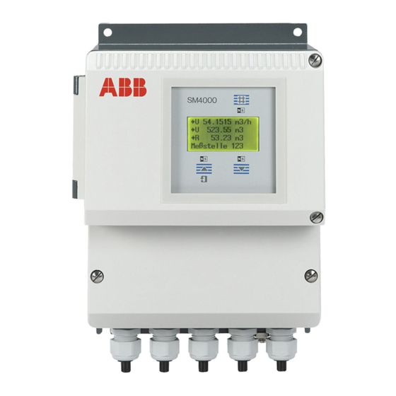
Fieldit electromagnetic flowmeter with ac field technology converter model s4
Hide thumbs Also See for FSM4000:
Table of Contents

Advertisement

Operating Instruction
D184B122U02
Valid for Software Levels from B.1X
For Flowmeter Primaries:
Models SE21_/SE41F
(OI D184B121U02)
Electromagnetic Flowmeter
with AC Field Technology
Converter Model S4
IT
Field
FSM4000
®
P R O F I
PROCESS FIELD BUS
B U S

Advertisement

Table of Contents
loading

Summary of Contents for ABB FSM4000

  • Page 1 Field Operating Instruction D184B122U02 Electromagnetic Flowmeter FSM4000 with AC Field Technology Converter Model S4 Valid for Software Levels from B.1X For Flowmeter Primaries: Models SE21_/SE41F (OI D184B121U02) ® P R O F I PROCESS FIELD BUS B U S...
  • Page 2 +49 (0) 55 19 05- 0 Fax: +49 (0) 55 19 05- 777 © Copyright 2004 by ABB Automation Products GmbH We reserve the right to technical amendments. This document is protected by copyright. Information in this document is intended only to assist the user in the safe and efficient operation of the equipment.
  • Page 3 Contents EASY-SETUP, for uncomplicated configuration ......5 Safety Information ........... . . 6 Basic Safety Requirements .
  • Page 4 System Installation ............46 8.5.5 Block Diagram of the FSM4000 with PROFIBUS PA Communication ....47 Maintenance .
  • Page 5: Easy-Setup, For Uncomplicated Configuration

    1 EASY-SETUP, for uncomplicated configuration EASY-SETUP, for uncomplicated configuration The EASY-SETUP function makes it possible to configure the converter for operation in the simplest and quickest possible manner. For additional configuration information, see the detailed descriptions beginning on Page 25. Press any key to exit Important! from the process display...
  • Page 6: Safety Information

    Operating Instruction. Extensive activities must be approved by us. Excepted are repairs made in locations authorized by ABB. For unauthorized activities we accept no liability. The operation and maintenance requirements in this Operating Instruction must be observed.
  • Page 7: Safety Marks, Symbols, Type And Factory Tags And Ce-Identification

    Power used by the converter and flowmeter primary • Design variant based on the ordering information with/ Rem.: Do not connect EEx-primaries without HART-Protocol or PROFIBUS PA ABB Automation Products GmbH 37070 Göttingen • Design variant based on the ordering information active (24 V- pulse at output)
  • Page 8: Qualification Of Personnel

    Returns • If it is necessary to return the instrument for repair or recalibration to the ABB factory in Göttingen, Ger- many, use the original packaging material or a suitably protective packing material. Please include the reason for the return. The flowmeter primary must be free of all hazardous materials (acids, bases, sol- vents, etc.).
  • Page 9: Flowmeter Primary And Converter Coordination

    Older models Series 3000/4000 MAG-SM S4 compatible DS41F/DS44F, 10DS3111/2, 10DS3121, 10DI1425, 10D1422 Operating Instructions Flowmeter Primary Converter ABB Part No.: D184B121U02 FSM4000 ABB Part No.: D184B122U02 Condensed Instructions Assembly and Installation ABB Part No.: D184B121U11 Specifications Converter FSM4000 ABB Part No.: D184S073U02...
  • Page 10: Assembly And Installation

    4 Assembly and Installation Assembly and Installation Inspection Before mounting the converter, check for mechanical damage due to improper handling during shipment. All claims for damages are to made promptly to the shipper prior to installation. Mounting the Converter The installation site for the converter must essentially be free of vibrations, see Specifications. The listed am- bient temperature limits between -20 °C and +60 °C are to be observed.
  • Page 11: Installation Examples

    4 Assembly and Installation Installation Examples min. 62 Opening the housing cover – Loosen the cover screws – Remove cover or flip open cover with window Closing the housing cover – Press the cover with the window on the side with the cover screws against the gasket and tighten the screws –...
  • Page 12: Electrical Interconnections Converter

    The voltage supply for the FSM4000 with a preamplifier is made over -U and +U, instead of over 1S and 2S. If the actual flow direction does not correspond to the flow direction arrow then leads connected to 1 and 1S must be interchanged with those connected to 2 and 2S.
  • Page 13 5 Electrical Interconnections Converter Important! The signal cable shields may not contact each other or the outer shields (signal short circuit). Jacket, PVC white Woven steel wire shield, ∅ natural 0.15 mm with SE bracket Woven copper wire shield , natural 0.13 mm Electrode signal ∅...
  • Page 14: Converter Field Mount Housing

    3) – 6) Output Cables See Page 18 Shielded Signal Cable: ABB Part No. D173D018U02, 10 m included in shipment. Comment: We recommend that shielded output cables be used with the shields connected to earth at one end. Fig. 5: Interconnection Diagram Standard DN 10 to DN 1000 [3/8”...
  • Page 15: Flowmeter Primary With Preamplifier Dn 1 To Dn 1000 [1/25" To 40"]

    3) – 6) Output Cables See Page 18 Shielded Signal Cable: ABB Part No. D173D018U02, 10 m included in shipment. Comment: We recommend that shielded output cables be used with the shields connected to earth at one end. Fig. 6: Interconnection Diagram DN 1 - DN 8[1/25”...
  • Page 16: Converter Field Mount Housing With Profibus Pa

    ≤ 2 mA Terminals: 41, 42 Shielded Signal Cable: ABB Part No. D173D018U02, 10 m included in shipment. Shielded Signal Cable: Voltage supply for flowmeter primary with preamplifier Terminals +U, -U instead of 2S and 1S in the standard instrument.
  • Page 17 Magnet Coil Supply from Supply Power 3) – 6) Output Cables see Page 18 Shielded Signal Cable: Use ABB Part No. D173D018U02 or incorporate into the existing wiring. Reference Cable: Only for connection to Model 10D1422 Reference Cable to Terminals: 6,7 Comment: We recommend that shielded output cables be used with the shields connected to earth at one end.
  • Page 18: Interconnection Examples For Peripherals

    5 Electrical Interconnections Converter Interconnection Examples for Peripherals Current Output Current output active with/without HART-Protocol (4–20 mA) internal external 0/4-20 mA 0/2-10 mA Current output: software selectable Function: Active 0/4–20 mA, 0/2−10 mA, 0 Ω ≤ R ≤ 560 Ω Terminals: 31, 32 Contact Output Contact output for System Monitor, Max.-Min.-Alarm, Empty Pipe or Fro-...
  • Page 19: Interconnection Examples Peripherals With Profibus Pa

    5 Electrical Interconnections Converter Interconnection Examples Peripherals with PROFIBUS PA PROFIBUS PA internal external The resistance R and the capacitor C form the bus termination. They are to be installed if the instrument is connected at the end of the bus. R = 100 Ohm;...
  • Page 20: Managing The Data Storage Module

    6 Managing the Data Storage Module Managing the Data Storage Module Data Storage Module FRAM (Ferroelectric Nonvolatile Random Access Memory) When the flowmeter primary and converter are shipped together, the data storage module (external FRAM) is plugged onto the flowmeter primary. Prior to start-up, the ext. FRAM should be plugged into the socket on the connection board in the converter.
  • Page 21: Start-Up

    7 Start-up Start-up Checks Before Turning on the Supply Power Before start-up of the instrument check that • the coordination between the flowmeter primary/converter is correct (important for converters with fixed flow range settings, flowmeter primary must be designed for AC technology), •...
  • Page 22: Data Entry

    After they have been successfully completed the standard display appears (process information). The variables to be displayed can be selected by the user. FSM4000 Data entry using a Magnet Stick without...
  • Page 23: Easy-Setup, For Uncomplicated Configuration

    8 Data Entry EASY-SETUP, for uncomplicated configuration The EASY-SETUP function makes it possible to configure the converter for operation simplest and quickest possible manner. For additional configuration information, see the detailed descriptions beginning on Page 25. Press any key to exit Important! from the process display The parameters can only...
  • Page 24: Parameter Overview And Data Entry

    Prog Level required to operate the instrument. Standard "Specialist": Contains all customer Prog Level accessible menu entries. Specialist "Service": additional menus displayed after Prog Level the correct Service Code number has been Service entered, only for ABB Service). Servicecode? ENTER D184B122U02...
  • Page 25 Submenu/ Submenu/ Submenu/ Selections Comments Parameter Parameter Parameter Value Range Prog Level PP-Code Normally the Prog. Protection Code is equal Old PP-Code: 1–9999 to "0". If the Prog. Prot. is selected, the ENTER question "New PP Code?" is displayed. If a code is entered between (1 and 9999) then an attempt to access the PP Code protect- ed menus by an operator will result in the...
  • Page 26 Submenu/ Submenu/ Submenu/ Selections Comments Parameter Parameter Parameter Value Range Standard, Invers Standard/Invers, reverse the flow direction Flow direction indicators in the display for forward and Standard reverse flow. Forward/Reverse When the flow indication "Forward/Reverse" Flow indication is selected the flow direction is indicated in Forward Forward/Reverse the display by "→...
  • Page 27 Submenu/ Submenu/ Submenu/ Selections Comments Parameter Parameter Parameter Value Range Submenu Systemdata Submenu ENTER Converter This menu is not displayed for PROFIBUS Submenu PA or for excitation frequencies 60 Hz or Data 50 Hz 70 Hz. Adjustment value for Channel can be moni- Channel view only tored for the excitation frequency setting...
  • Page 28 Submenu/ Submenu/ Submenu/ Selections Comments Parameter Parameter Parameter Value Range Adjustment value for Zero can be monitored Zero view only for the excitation frequency setting (dis- played when a new flowmeter primary was selected). Span → F Adjustment value for Span Forward can be view only monitored for the excitation frequency set- 91 %...
  • Page 29 Display of the reference voltage value, for Reference voltage view only selection "Older Model". Not displayed for 70 mV Model 10D1422. Display of the ABB-Order Number of the Order Number view only flowmeter primary. „----------------------“ Only for selection Display required for "Older Model". Use EN- Primary Setup „Older Model“...
  • Page 30 Submenu/ Submenu/ Submenu/ Selections Comments Parameter Parameter Parameter Value Range Display of the mains frequency for the flow- Mains frequency view only meter primary. Selections only available for 50 Hz „Older Model“. Display of the type of flowmeter primary Type of Primary view only connected.
  • Page 31 Submenu/ Submenu/ Submenu/ Selections Comments Parameter Parameter Parameter Value Range Standard Selection of the function „Standard“ or DEP Mode New Adjust „New Adjust“. The converter is shipped with Standard the „Standard“ DEP Mode set. For most applications the DEP function will operate satisfactorily in the „Standard“...
  • Page 32 Submenu/ Submenu/ Submenu/ Selections Comments Parameter Parameter Parameter Value Range Q [Percent]; Q [Unit]; Selections for the 1st display line Display 1st line Iout [mA]; Q [Percent] Q [m/s]; Q Bargraph Totalizer; → Totalizer Totalizer ← R; Totaliz- er Diff.; HART TAG; Detector e.
  • Page 33 Submenu/ Submenu/ Submenu/ Selections Comments Parameter Parameter Parameter Value Range FB TOT1 Total Here the Total-Value of the Display 1st line Totalizer-Block is displayed. The displayed FB TOT1 Total unit is the UNIT_TOTAL. FB TOT1 Status Here the Actual-Mode of the particular Block and the Status of the Output-Variables (Total.
  • Page 34 Submenu/ Submenu/ Submenu/ Selections Comments Parameter Parameter Parameter Value Range The function of the totalizer is automatically Submenu set based on the selection in the submenu Totalizer "Operating mode". Operating mode Stan- dard = totalizer function Standard, Operating mode Piston Pump = totalizer function Difference totalizer.
  • Page 35 Submenu/ Submenu/ Submenu/ Selections Comments Parameter Parameter Parameter Value Range Low Alarm Behavior of the current output during an Iout at Alarm alarm condition. Low-Alarm is only available High Alarm Low Alarm for current output selections 2-10 mA and 4-20 mA. If error 0 (empty pipe) occurs, the current output is set to the value pro- grammed for the parameter "Iout at empty pipe"...
  • Page 36 Submenu/ Submenu/ Submenu/ Selections Comments Parameter Parameter Parameter Value Range No function The switch status of the Contact Output Contact output (Terminals 41/42) can be selected as nor- F/R-Signal /_ No function mally open (/_) or normally closed (_ _). For F/R-Signal __ the "General-Alarm"...
  • Page 37 Factory setting for the switch is : OFF Setting the Ident-Number-Selectors. IdentNo Selctor The settings cannot be changed when cycli- FSM4000 0x078C cal operation is not active, only during status AI + 2* TOT STOP. Profile 0x078C: AI + 2* TOT (AI-Block + 2...
  • Page 38 Submenu/ Submenu/ Submenu/ Selections Comments Parameter Parameter Parameter Value Range Channel setting for the AI-Block. AI Channel When setting the channel, the Unit for the TB Flow Value channel is also copied to the AI-Block (from OUT_SCALE. UNIT_INDEX). Selection: TB (Transducer Block) Flow Value AI Channel TB Total →...
  • Page 39 Submenu/ Submenu/ Submenu/ Selections Comments Parameter Parameter Parameter Value Range This memory is not displayed for PROFIBUS Contact input Test the Contact Input. Before a signal is applied to the Contact Input, the text "Off" is displayed in this menu; after a signal is applied the text "On"...
  • Page 40 ± 10%. If the value is outside of these limits, the adjustment is rejected. view only Display of the software revision. 08/2003 FSM4000 08/2003 identifies the issue date.B. 10 = Revision D699G004U01 B.10 level for the Standard and HART-Protocol software.
  • Page 41: Hart®-Communication

    4–20 mA current output. Please see the Operating Instruction for the Handheld Terminal for details. The software program SMART VISION from ABB can be used in the control room or the service area to monitor and evaluate the data from field instruments utilizing the HART-Protocol. The SMART VISION program includes the ability to configure and display the process relevant variables with a periodic self monitoring function to check the connected field instruments.
  • Page 42 Application Spectrum • Configuration and setting parameters in field instruments. • Diagnosis of instruments, access status messages. • Visual overview of the instruments connected to the system using a picture of the connections. • Storage/management of instrument data. • Instrument measurement site planning and management •...
  • Page 43: Interconnection Options Hart

    8.4.3 Interconnection Options HART a) „Point-to-Point“ Using a FSK-Modem (Notebook/Desktop) SMART VISION SMART HART-FSK-Modem VISION Galvanic isolation, Ex-Protection RS232 [EEx ib] incl. connection cable 4/2 mm and 4/4 mm Field Instrument Power Supply 4..20 mA + FSK HART-FSK-Modem Clip on version, Galvanic isolation with Address “0”...
  • Page 44: Profibus Pa

    This section of the Operating Instruction contains information for the converter with the Communication PROFIBUS PA option. The converter is designed to be connected to a Segment Coupler DP/PA as well as the ABB Multibarrier MB204. The PROFIBUS PA data link in the FSM4000 conforms to Profile 3.0 (Fieldbus Standard PROFIBUS, EN 50170, alias DIN 19245[PRO91]).
  • Page 45: Layout And Design Information

    Additional detailed layout and design information may be found in the Brochure "PROFIBUS - Solutions from ABB" (No.30/FB-10). Accessories such as splitters, connectors and cables may be found in List Sheet 10/ 63-6.44. Additional information is available on the PROFIBUS Organization home web page at http:// www.profibus.com.
  • Page 46: Information For Voltage / Current Usage

    The power on condition corresponds to the Draft DIN IEC 65C / 155 / CDV of June 1996. The average current usage by the FSM4000 on the bus is 10 mA. During a fault condition the FDE-Function (Fault Disconnection Electronic) integrated in the instrument assures that the current usage cannot exceed 13 mA.
  • Page 47: Block Diagram Of The Fsm4000 With Profibus Pa Communication

    Block Diagram of the FSM4000 with PROFIBUS PA Communication The diagram is presented as a function block diagram showing the blocks available in the FSM4000. Acyclically a communication tool or a SPC with Master Class 2 functionality can access all blocks for configuration.
  • Page 48: Maintenance

    9 Maintenance Maintenance General Attention! The are electrostatic sensitive parts on the circuit boards (observe EGB-Directives). Be sure that you are electrostatically discharged before touching the electronic components. Information about the Exchangeability of the Converter S4 The converter module is identical in function for all Meter Sizes DN 1 to DN 1000 [1/25” to 40”] and can be easily exchanged.
  • Page 49: Converter Exchange With Profibus Pa

    Part No. D184B049U02. The test should only be conducted by authorized technicians. Information! There are a number of training sessions conducted annually at the main ABB plant covering installation, start-up, error search, and all parameter functions. For additional information please contact us.
  • Page 50: Messages And Tests

    9 Maintenance Messages and Tests 9.8.1 Overview of the Error Conditions and Alarms Error Code and Clear Flowrate Messages While Current Output Pulse Contact Output Message with Text Message Display Simulating Output HART General Min- Max- Max/Min- Empty Current Output Alarm Alarm Alarm...
  • Page 51: Error Messages During Operation And When Entering Data

    If the start-up cannot be completed because of a missing or defective FRAM then a new FRAM can be ordered from the Service Dept. at the factory at Göttingen, Germany. The ABB Order Number and Instrument Number of the flowmeter primary must be included with the order.
  • Page 52: Warning Messages During Operation

    2)3) Warning. 13 Warning displayed only in Service Code section Only for Only for ABB Service Personnel Automatic adjustment when an adjustment has been initiated (only ABB Service Personnel running accessible to ABB Service). Warning. 14...
  • Page 53: Checking The Metering System

    9 Maintenance 9.8.4 Checking the Metering System Warning! STOP When the housing cover is open and the supply power is turned on the personnel contact protection is no longer provided! The check of the metering system follows the assembly and installation the flowmeter primary and converter. Are the flowmeter primary and converter installed at Allowable installation requirements: check tempera- the correct location? (is the coordination correct, Tag-...
  • Page 54: Pulse Output, Change Active/Passive

    9 Maintenance Pulse Output, Change Active/Passive The factory setting for the pulse output is noted on the type tag on the converter can be obtained from the Ordering Information (Model Number). Use the following procedure if a change is required: •...
  • Page 55: Connection Board Field Mount Housing

    9 Maintenance 9.10 Connection Board Field Mount Housing ≥ The switch S903 (option) is closed for the older model primaries 10D1422, 10DI1425 ( DN 500 [20”]) Switch S903 is opened for all the other older model primaries, see Page 60, and for flowmeter prima- ries SE21_/SE41F, or the parts may not be installed for this models.
  • Page 56 4. Replace the defective fuse (4.0 A slo-blow) Replacement part No. D151B002U07 5. Reinstall protection cap F101 6. Press the large cover against the gaskets on the open side and tighten the cover screws 7. Turn on the supply power Information! Use only original ABB replacement parts! D184B122U02...
  • Page 57: Digital-I/O Board

    9 Maintenance 9.11 Power Supply Board) R126 R125 C164 + C163 R134 R130 R129 R135 + C127 R137 MP102 L103 L104 C103 R123 C152 C153 C154 C161 C121 C149 C167 C160 C116 C159 C118 C131 C144 C151 V110 V112 C120 C104 C117 C110...
  • Page 58: Replaceable Parts List Converter Field Mount Housing

    9 Maintenance 9.13 Replaceable Parts List Converter Field Mount Housing (Backside) Cover large View without cover. 11,12 (Backside) Cover small Fig. 28: Replaceable Parts Converter Field Mount Housing Description Part No. Converter U high voltage without HART D674A859U01 Converter U high voltage with HART D674A859U02 Converter U high voltage with PROFIBUS PA D674A859U03...
  • Page 59: Replaceable Parts List Converter

    9 Maintenance 9.14 Replaceable Parts List Converter TTL Plug 9,10 10pole Plug from display board plugged in. Fig. 29: Replaceable Parts Converter Description Part No. Driver Board D685A1016U01 Front End Board D685A1017U01 Digital-I/O Board Standard D685A1018U01 Digital-I/O Board HART D685A1018U02 Digital-I/O Board PROFIBUS PA D685A1032U01 Power Supply Board Standard U...
  • Page 60: Supplementary Information, Operating S4 With An Older Models

    10 Supplementary Information, Operating S4 with an Older Models Supplementary Information, Operating S4 with an Older Models Older Models, selections for operating with converter S4 Procedure: If a converter is to be operated with an older model flowmeter primary then a FRAM with the values Cs=100 % and Cz=0 % must be used.
  • Page 61: Supplementary Configuration Information

    11 Supplementary Configuration Information Supplementary Configuration Information 11.1 Supplementary Information for Configuring the Pulse Output The scaled pulse output uses 1-channel and can be configured as an active (24 V DC) or passive (optocoupler) pulse. To change mode after start-up, see Chapter 9.9. To configure the following parameter settings are to considered.
  • Page 62: Supplementary Information For Configuring Piston Pump/Pulsation

    11 Supplementary Configuration Information 11.2 Supplementary Information for Configuring Piston Pump/Pulsation Parameter Entry Comments The main application areas for the AC magnetic field instruments are where fast mea- surement processing is required for continuous flow metering of single or multi phase Submenu fluids.
  • Page 63: Specifications Fsm4000

    12 Specifications FSM4000 Specifications FSM4000 12.1 General Description The Converter Model S4 converts the flowrate proportional flow signals from an electromagnetic flowmeter primary into the conventional output signals. These measurement values are shown on a full-graphic 4 line lighted display. In addition, the measurement values are also transmitted to a scaled pulse output, current output and using HART-Protocol communication.
  • Page 64: Accuracy Under Reference Conditions Per En29104

    12 Specifications FSM4000 Contact input Active as operating contact (normally open) optocoupler specifications: „On“ 16V ≤ U ≤ 30 V DC, „Off“ 0V ≤ U ≤ 2 V DC, R 0= 2 kΩ The following functions can be assigned: Ext. zero return, ext. totalizer reset...
  • Page 65: Reference Conditions Per En 29104

    12 Specifications FSM4000 12.4 Reference Conditions per EN 29104 Fluid temperature 20 °C ± 2 K Ambient temperature 20 °C ± 2 K Supply power Unom ± 1 % At reference conditions the supply power is restricted to a fixed value...
  • Page 66: Parameter Setting And Option Overview

    13 Parameter Setting and Option Overview Parameter Setting and Option Overview Meter Location: TAG-No.: Flowmeter Primary Type: Converter Type: Order No.: Instrument No.: Order No.: Instrument No.: Fluid Temp.: Supply Power: Liner: Electrodes: Excitation Frequency: System Zero: Phase: Reference Voltage: Parameter Setting Range Prog.
  • Page 67: Eu Certificate Of Compliance

    14 EU Certificate of Compliance EU Certificate of Compliance D184B122U02...
  • Page 68 ABB. information contained herein without notice. ABB has Sales & Customer Support Printed in the Fed. Rep. of Germany (04.2004) expertise in over 100 countries worldwide. © ABB 2004 www.abb.com...

This manual is also suitable for:

Se21 seriesSe41f

Table of Contents