WAGNER Cobra 40-10 Translation Of The Original Operating Manual
High-pressure double diaphragm pumps
Hide thumbs
Also See for Cobra 40-10:
- Translation of the original operating manual (100 pages) ,
- Original operating manual (84 pages) ,
- Operating manual (72 pages)
Table of Contents
Advertisement
Quick Links
Download this manual
See also:
Operating Manual
Advertisement
Table of Contents

Related Manuals for WAGNER Cobra 40-10


Summary of Contents for WAGNER Cobra 40-10
- Page 1 Translation of the Original Operating Manual Version 07/2014 High-pressure Double Diaphragm Pumps B_04234 B_04233...
-
Page 3: Table Of Contents
4.1.1 Electrical Equipment 4.1.2 Staff Qualifi cations 4.1.3 Safe Work Environment Safety Instructions for Staff 4.2.1 Safe Handling of WAGNER Spray Devices 4.2.2 Grounding the Device 4.2.3 Product Hoses 4.2.4 Cleaning and Rinsing 4.2.5 Handling Hazardous Liquids, Lacquers and Paints 4.2.6... - Page 4 ORDER NUMBER DOC2340851 VERSION 07/2014 OPERATING MANUAL Table of Contents ASSEMBLY AND COMMISSIONING Training Assembly/Commissioning Staff Storage Conditions Installation Conditions Transportation Assembly and Installation 6.5.1 Ventilation of the Spray Booth 6.5.2 Air Supply 6.5.3 Product Supply Grounding Safety Checks Commissioning 6.8.1 Safety Instructions 6.8.2...
- Page 5 Cobra 40-10 Accessories 13.2 Cobra 40-25 Accessories SPARE PARTS 14.1 How Can Spare Parts Be Ordered? 14.2 Overview of the Cobra 40-10 Components 14.3 Cobra 40-10 Air Motor 14.4 Cobra 40-10 Fluid Section 14.5 Overview of the Cobra 40-25 Components 14.6...
-
Page 6: About This Manual
ORDER NUMBER DOC2340851 VERSION 07/2014 OPERATING MANUAL ABOUT THIS MANUAL PREFACE The operating manual contains information about safely operating, maintaining, cleaning and repairing the device. The operating manual is part of the device and must be available to operating and service staff . -
Page 7: Languages
ORDER NUMBER DOC2340851 VERSION 07/2014 OPERATING MANUAL LANGUAGES The operating manual is available in the following languages: Language Order No. Language Order No. German 2340850 English 2340851 French 2340852 Italian 2340853 Spanish 2340854 Russian 2345830 Japanese 2346196 Additional languages on request or at: ABBREVIATIONS IN THE TEXT Number of pieces Position... -
Page 8: Correct Use
The double diaphragm pump can be employed in explosion hazard areas (Zone 1). SAFETY PARAMETERS WAGNER accepts no liability for any damage arising from non-intended use. Use the device only to work with the products recommended by WAGNER. Operate only the device as a whole. Do not deactivate safety fi xtures. -
Page 9: Processible Working Materials
ORDER NUMBER DOC2340851 VERSION 07/2014 OPERATING MANUAL PROCESSIBLE WORKING MATERIALS Fluid products such as paints and lacquers. Application Water-dilutable products Solvent-based lacquers and paints Two-component coating products Emulsions UV lacquers Primers Epoxy and polyurethane lacquers, phenolic lacquers Liquid plastics Wax-based underside protection Shear-sensitive lacquers Legend recommended... -
Page 10: Reasonably Foreseeable Misuse
The forms of misuse listed below may result in physical injury or property damage: use of powder as coating product and incorrectly set values for processing. Wagner double diaphragm pumps are not designed for pumping food. RESIDUAL RISKS Residual risks are risks which cannot be excluded even in the event of correct use. -
Page 11: Identification
The permissible ambient temperature is: +10 °C to +60 °C; +50 °C to 140 °F. Medium supporting atomizing To atomize the product, use only weakly oxidizing gases, e.g., air. Safe handling of WAGNER spray devices Mechanical sparks can form if the device comes into contact with metal. In an explosive atmosphere: Do not knock or push the device against steel or rusty iron. -
Page 12: Type Plates
Periodically check that the pump is working, paying special attention to the presence of air in the pumped fl uid, which may be caused by damaged diaphragms. Avoid operating the pump with damaged diaphragms. TYPE PLATES Example for Cobra 40-10 J. WAGNER AG CH-9450 ALTSTÄTTEN II 2G IIB c X... -
Page 13: General Safety Instructions
ORDER NUMBER DOC2340851 VERSION 07/2014 OPERATING MANUAL GENERAL SAFETY INSTRUCTIONS SAFETY INSTRUCTIONS FOR THE OPERATOR Keep this operating manual on hand near the device at all times. Always follow local regulations concerning occupational safety and accident prevention. 4.1.1 ELECTRICAL EQUIPMENT Electrical devices and equipment To be provided in accordance with the local safety requirements with regard to the operating mode and ambient infl uences. -
Page 14: Safety Instructions For Staff
If necessary or at least every 12 months, the liquid ejection devices should be checked for safe working conditions by an expert (e.g., Wagner Service Technician) in accordance with the guidelines for liquid ejection devices (ZH 1/406 and BGR 500 Part 2 Chapter 2.29 and 2.36). -
Page 15: Grounding The Device
ORDER NUMBER DOC2340851 VERSION 07/2014 OPERATING MANUAL 4.2.2 GROUNDING THE DEVICE In order to avoid electrostatic charging of the device, the device must be grounded. Friction, fl owing liquids, and air or electrostatic coating processes create charges. Flames or sparks can form during discharge. Ensure that the device is grounded for every spraying operation. -
Page 16: Cleaning And Rinsing
ORDER NUMBER DOC2340851 VERSION 07/2014 OPERATING MANUAL 4.2.4 CLEANING AND RINSING Relieve the pressure from the device. De-energize the device electrically. Preference should be given to non-fl ammable cleaning and fl ushing agents. Observe the specifi cations of the paint manufacturer. Ensure that the fl ash point of the cleaning agent is at least 15 K above the ambient temperature or that cleaning is undertaken at a cleaning station with technical ventilation. -
Page 17: Touching Hot Surfaces
ORDER NUMBER DOC2340851 VERSION 07/2014 OPERATING MANUAL 4.2.6 TOUCHING HOT SURFACES Only touch hot surfaces if you are wearing protective gloves. When operating the device with a coating product with a temperature of > 43 °C; 109.4 °F: - Mark the device with a warning label "Warning – hot surface". Order No. -
Page 18: Description
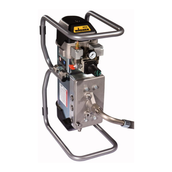
ORDER NUMBER DOC2340851 VERSION 07/2014 OPERATING MANUAL DESCRIPTION DESIGN Cobra 40-10 Control housing with integrated silencer Air pressure regulator Ball valve Air motor Compressed air inlet Mounting fl ange Relief valve Product outlet B_04237 Fluid section Cobra 40-25 Product inlet... -
Page 19: Fluid Section
ORDER NUMBER DOC2340851 VERSION 07/2014 OPERATING MANUAL WARNING Overpressure! Risk of injury from bursting components. Never change the safety valve setting. 5.2.4 FLUID SECTION (9) The fl uid section has been designed as a double diaphragm pump with exchangeable inlet and outlet valves. Change between "spraying mode" and "circulation mode" using the relief valve (7). -
Page 20: Scope Of Delivery
2329519 Diaphragm pump Cobra 40-10 consisting of: Fluid section, air motor, connection elements 2329521 Frame-mounted diaphragm pump Cobra 40-10 consisting of: Fluid section, air motor, connection elements 2329523 Diaphragm pump Cobra 40-25 consisting of: Fluid section, air motor, connection elements... - Page 21 ORDER NUMBER DOC2340851 VERSION 07/2014 OPERATING MANUAL Description Devices Air inlet (inside thread) inch G 1/2 G 1/2 Minimum Ø of the compressed air supply line inch 0.51 0.75 Air consumption at 0.6 MPa; 6 bar; 87 psi per double stroke Sound pressure level at maximum dB(A) permissible air pressure*...
-
Page 22: Measurements And Connections
ORDER NUMBER DOC2340851 VERSION 07/2014 OPERATING MANUAL 5.4.3 MEASUREMENTS AND CONNECTIONS Cobra 40-10 B_02943 B_04235 Measurement mm; inch mm; inch 505; 19.88 605; 23.82 313; 12.32 379; 14.92 322; 12.68 373; 14.69 134; 5.28 134; 5.28 55; 2.16 55; 2.16 182;... -
Page 23: Volume Flow
ORDER NUMBER DOC2340851 VERSION 07/2014 OPERATING MANUAL 5.4.4 VOLUME FLOW Wagner AL nozzles Volume fl ow in l/min.* inch mm Spray angle 7 MPa 10 MPa 15 MPa 70 bar 100 bar 150 bar 1015 psi 1450 psi 2175 psi 0.007... - Page 24 ORDER NUMBER DOC2340851 VERSION 07/2014 OPERATING MANUAL Diagram for Cobra 40-10 Stroke frequency ( /min) nl/min bar (MPa) NL/min <scfm> <psi> 250 (25) 1000 <3625> <35> 200 (20) <2900> <28> 150 (15) <2175> <21> 100 (10) <1450> <14> 50 (5) <725>...
-
Page 25: Pressure Regulator Unit For Cobra
ORDER NUMBER DOC2340851 VERSION 07/2014 OPERATING MANUAL PRESSURE REGULATOR UNIT FOR COBRA 1 Pressure regulator 2 Ball valve 3 Pressure gauge 4 Compressed air inlet 5 AirCoat fi lter regulator Cobra (accessories) The AirCoat fi lter regulator must be mounted vertically in all installation positions for the diaphragm pump (see assembly manual for Filter Regulator, order number 2328614). -
Page 26: Assembly And Commissioning
ORDER NUMBER DOC2340851 VERSION 07/2014 OPERATING MANUAL ASSEMBLY AND COMMISSIONING TRAINING ASSEMBLY/COMMISSIONING STAFF WARNING Incorrect installation/operation! Risk of injury and damage to the device. The assembly and commissioning staff must have the technical skills to safely undertake commissioning. When assembling, commissioning and carrying out all work, read and follow the operating manuals and safety regulations for the additionally required system components. -
Page 27: Assembly And Installation
ORDER NUMBER DOC2340851 VERSION 07/2014 OPERATING MANUAL ASSEMBLY AND INSTALLATION Note: This pump can be used as part of a spraying system for Airless or AirCoat applications. The components can be found in the accessories list, provided that the system was not obtained as a spray pack. -
Page 28: Ventilation Of The Spray Booth
ORDER NUMBER DOC2340851 VERSION 07/2014 OPERATING MANUAL 6.5.1 VENTILATION OF THE SPRAY BOOTH WARNING Toxic and/or fl ammable vapor mixtures! Risk of poisoning and burns Operate the device in a spray booth approved for the working materials. – or – Operate the device on an appropriate spraying wall with the ventilation (extraction) switched on. -
Page 29: Grounding
ORDER NUMBER DOC2340851 VERSION 07/2014 OPERATING MANUAL GROUNDING WARNING Discharge of electrostatically charged components in atmospheres containing solvents! Explosion hazard from electrostatic sparks. Only use a damp cloth to clean the piston pump. WARNING Heavy paint mist if grounding is insuffi cient! Danger of poisoning. -
Page 30: Safety Checks
ORDER NUMBER DOC2340851 VERSION 07/2014 OPERATING MANUAL Cable cross sections Pump 4 mm2; Paint tank 6 mm2; Conveyor 16 mm2; Booth 16 mm2; Spraying stand 16 mm2; Procedure: 1 Screw on grounding cable with eye. 2 Clamp the grounding cable clip to a grounding connection on site. -
Page 31: Commissioning
ORDER NUMBER DOC2340851 VERSION 07/2014 OPERATING MANUAL COMMISSIONING 6.8.1 SAFETY INSTRUCTIONS Every time before starting up, the following points should be observed as laid down in the operating manual: - Observe all safety regulations in accordance with Chapter 4. - Carry out commissioning properly. WARNING High-pressure spray jet! Danger to life from injecting paint or solvent. -
Page 32: Preparation For Commissioning
ORDER NUMBER DOC2340851 VERSION 07/2014 OPERATING MANUAL 6.8.2 PREPARATION FOR COMMISSIONING NOTICE Impurities in the spraying system! Clogging of the spray gun Flush the spray gun and paint supply with a suitable fl ushing agent before commissioning. 6.8.3 BASIC FLUSHING 1 Place empty tank (5) under return tube (4). -
Page 33: Filling With Working Material
ORDER NUMBER DOC2340851 VERSION 07/2014 OPERATING MANUAL 6.8.4 FILLING WITH WORKING MATERIAL Positions of the ball valve Open: working position Closed: The air motor can still be under pressure. Vent: Operating pressure in the air motor is vented (control pressure is still present). B_04301 1 Place suction hose (7) and return tube (4) into the tank with the working material (6). -
Page 34: Operation
ORDER NUMBER DOC2340851 VERSION 07/2014 OPERATING MANUAL OPERATION TRAINING THE OPERATING STAFF WARNING Incorrect operation! Risk of injury and damage to the device. The operating staff must be qualifi ed and fi t to operate the entire system. The operating staff must be familiar with the potential risks associated with improper behavior as well as the necessary protective devices and measures. -
Page 35: Emergency Deactivation
ORDER NUMBER DOC2340851 VERSION 07/2014 OPERATING MANUAL EMERGENCY DEACTIVATION EMERGENCY STOP In the event of unforeseen occurrences, the ball valve (1) should be vented immediately and the relief valve (2) opened. B_04099 vent ➀ ➁ Switch position Circulation B_04303 B_04302 Open... -
Page 36: Work
ORDER NUMBER DOC2340851 VERSION 07/2014 OPERATING MANUAL WORK Positions of the ball valve Open: working position Closed: The air motor can still be under pressure. Vent: Operating pressure in the air motor is vented (control pressure is still present). Secure gun and place nozzle in the gun. B_04301 Slowly open the ball valve. - Page 37 ORDER NUMBER DOC2340851 VERSION 07/2014 OPERATING MANUAL WARNING High-pressure spray jet! Danger to life from injecting paint or solvent. Never reach into the spray jet. Never point the spray gun at people. Consult a doctor immediately in the event of skin injuries caused by paint or solvent.
-
Page 38: Cleaning And Maintenance
ORDER NUMBER DOC2340851 VERSION 07/2014 OPERATING MANUAL CLEANING AND MAINTENANCE CLEANING 8.1.1 CLEANING STAFF Cleaning work should be undertaken regularly and carefully by qualifi ed and trained staff . They should be informed of specifi c hazards during their training. The following hazards may arise during cleaning work: - Health hazard from inhaling solvent vapors - Use of unsuitable cleaning tools and aids... -
Page 39: Cleaning And Flushing Device
DANGER Incorrect maintenance/repair! Danger to life and damage to the device. Only a WAGNER service center or a suitably trained person may carry out repairs and replace parts. Only repair and replace parts that are listed in the "Spare Parts"... -
Page 40: Maintenance
In accordance with the guideline for liquid ejection devices (ZH 1/406 and BGR 500 Part 2 Chapter 2.29 and Chapter 2.36): - The liquid ejection devices should be checked by an expert (e.g., Wagner service technician) for their safe working conditions as required and at least every 12 months. -
Page 41: Safety Checks
ORDER NUMBER DOC2340851 VERSION 07/2014 OPERATING MANUAL 8.2.3 SAFETY CHECKS WAGNER recommends having all spraying devices checked annually by a technical expert (e.g., WAGNER service technician) for safety reasons. 8.2.3.1 GROUNDING CHECK Every day Before starting work, carry out a visual check to ensure that the earthing connection is present in the device and in all relevant components. -
Page 42: Product Hoses, Tubes And Couplings
– 6 years from the date of the hose crimping (see fi tting embossing). – 10 years from the date of the hose imprinting. Fitting Hose imprinting Meaning Meaning embossing Name / Wagner xxx bar Pressure Manufacturer Crimping date Date of yymm (year/month) -
Page 43: Hydraulic Stage Maintenance
Screw in threaded plug (5) and tighten with 2 Nm; 1.5 lbft. NOTICE Using hydraulic oil Using the wrong hydraulic oil can cause a malfunction. Use only original hydraulic oil - Wagner Order No. 322912 (250 ml or 15 cu inch). -
Page 44: Changing The Oil
NOTICE Using hydraulic oil Using the wrong hydraulic oil can cause a malfunction. Use only original hydraulic oil - Wagner Order No. 322912 (250 ml or 15 cu inch). Discharging oil Procedure: Decommission and clean the device -> Chapter 8.1.3 up to and including point 6. - Page 45 ORDER NUMBER DOC2340851 VERSION 07/2014 OPERATING MANUAL CAUTION Environmental pollution caused by waste oil! Waste oil in the sewage network or spilled on the ground causes severe environmental damage. Groundwater pollution is liable to prosecution. Collect waste oil and bring it to a collection point. Waste oil is taken back by the seller when purchasing hydraulic oil.
- Page 46 ORDER NUMBER DOC2340851 VERSION 07/2014 OPERATING MANUAL Vent Procedure: Turn the pump upside down. Remove the threaded plug (5). Slowly start up (vent) the pump until no air bubbles appear from the oil suction fi tting. Oil level A in the oil tank has to be within the specifi ed markings (X). Screw in threaded plug (5) and tighten with 2 Nm;...
-
Page 47: Troubleshooting, Maintenance, And Repair
ORDER NUMBER DOC2340851 VERSION 07/2014 OPERATING MANUAL TROUBLESHOOTING, MAINTENANCE, AND REPAIR TROUBLESHOOTING AND RECTIFICATION Problem Cause Remedy Pump does not work. Air motor does not work or stops. Open and close ball valve on the pressure regulator unit or briefl y disconnect compressed air supply. - Page 48 Loss of power due to severe There is a lot of condensation Install a water separator. icing. water in the air supply. If none of the causes of malfunction mentioned are present, the defect can be remedied by a WAGNER Service Center.
-
Page 49: Repair Work
In accordance with the guideline for liquid ejection devices (ZH 1/406 and BGR 500 Part 2 Chapter 2.29 and Chapter 2.36): - The liquid ejection devices should be checked by an expert (e.g., Wagner service technician) for their safe working conditions as required and at least every 12 months. -
Page 50: Cleaning The Parts After Disassembly
ORDER NUMBER DOC2340851 VERSION 07/2014 OPERATING MANUAL 10.3 CLEANING THE PARTS AFTER DISASSEMBLY ATTENTION Please note: All reusable parts (except for the electrical components) should be cleaned thoroughly using a suitable cleaning agent. Spare parts may have safety-relevant properties. Defective parts, O-rings and seal sets must always be re-placed. WARNING Incompatibility of cleaning agent and working medium! Risk of explosion and danger of poisoning by toxic gases... -
Page 51: Functional Check After Repair
ORDER NUMBER DOC2340851 VERSION 07/2014 OPERATING MANUAL FUNCTIONAL CHECK AFTER REPAIR After all repairs, the device must be checked for safe condition before recommissioning. The necessary scope of inspection and testing depends on the repair carried out and must be documented by the repair staff . Aid tools Activities 1.1 Piston Travel... - Page 52 ORDER NUMBER DOC2340851 VERSION 07/2014 OPERATING MANUAL Aid tools Activities 1.5 General Inspections Check tightening torque of various screws. Torque wrench Tighten hexagon screws M12x65 (40-10) or M16x80 (40-25) and Visual check input valve housing with the prescribed torque. (see Chapter 14) Check all threaded connections Empty device completely and relieve pressure Check function of frame or transport trolley.
-
Page 53: Disposal
ORDER NUMBER DOC2340851 VERSION 07/2014 OPERATING MANUAL DISPOSAL When the equipment must be scrapped, please diff erentiate the disposal of the waste materials. The following materials have been used: - Stainless steel - Aluminum - Elastomers - Plastics - Carbide Consumable products (lacquers, adhesives, fl ushing and cleaning agents, solvents) must be disposed of in accordance with all applicable legal requirements. -
Page 54: Accessories
ORDER NUMBER DOC2340851 VERSION 07/2014 OPERATING MANUAL ACCESSORIES 13.1 COBRA 40-10 ACCESSORIES Accessories list for Cobra 40-10 Order No. Designation 2329519 Diaphragm pump Cobra 40-10 322912 Hydraulic oil (for pressure stage) 250 ml; 250 cc 236219 Grounding cable 3 m; 9.8 ft... - Page 55 ORDER NUMBER DOC2340851 VERSION 07/2014 OPERATING MANUAL Cobra 40-10 AirCoat Note: When the fi tting at the material outlet is replaced (item 55/57), a new sealing ring (item 58) must also be installed. 10,19 30,31 B_04234 B_04248...
-
Page 56: Cobra 40-25 Accessories
ORDER NUMBER DOC2340851 VERSION 07/2014 OPERATING MANUAL 13.2 COBRA 40-25 ACCESSORIES Accessories list for Cobra 40-25 Order No. Designation 2329523 Diaphragm pump Cobra 40-25 322912 Hydraulic oil (for pressure stage) 250 ml; 250 cc 236219 Grounding cable 3 m; 9.8 ft 2333479 AirCoat fi lter pressure regulator 341434... - Page 57 ORDER NUMBER DOC2340851 VERSION 07/2014 OPERATING MANUAL Note: Cobra 40-25 When the fi tting is replaced at the material output (item 55/57/58/59), a new sealing ring (item 60/61) must also be installed. AirCoat 57/58 10,19 60/61 30,31 12 12 B_04249...
-
Page 58: Spare Parts
Incorrect maintenance/repair! Risk of injury and damage to the device. Have repairs and part replacements carried out only by specially trained staff or a WAGNER service center. Before all work on the device and in the event of work interruptions: - Switch off the energy/compressed air supply. -
Page 59: Overview Of The Cobra 40-10 Components
ORDER NUMBER DOC2340851 VERSION 07/2014 OPERATING MANUAL 14.2 OVERVIEW OF THE COBRA 40-10 COMPONENTS Order No. Designation Air motor 3/53 Preassembled Cobra 40-10 fl uid section 322436 Air motor casing 322437 Pressure stage casing 322235 Hood 4 with air outlet... -
Page 60: Cobra 40-10 Air Motor
ORDER NUMBER DOC2340851 VERSION 07/2014 OPERATING MANUAL 14.3 COBRA 40-10 AIR MOTOR Order No. Designation 9998718 Drive fastener 367318 Shoulder screw 4 9925033 Washer 367311 Hood 4 367319 Sound absorbing mat 4 9999152 Velcro fastener coating part 9999151 Velcro fastener adhesive part... - Page 61 ORDER NUMBER DOC2340851 VERSION 07/2014 OPERATING MANUAL 10-15 Nm; 7-11 lbft Cobra 40-10 20-25 Nm; 15-18 lbft 2-3 Nm; 1.5-2.2 lbft Do not dismount the piston B_04251...
- Page 62 Loctite 222 50 ml; 50 cc 9992831 Loctite 542 50 ml; 50 cc 9992616 Molykote DX grease 2341627 Cobra 40-10 air motor service set = Wearing part = Included in service set = Not part of the standard equipment but available as a special accessory.
-
Page 63: Cobra 40-10 Fluid Section
Washer 341241 Inlet valve depressor, complete, see Chapter 14.10 2330764 Inlet housing = Wearing part = Included in the service set for Cobra 40-10 fl uid section. = Not part of the standard equipment but available as a special accessory. - Page 64 ORDER NUMBER DOC2340851 VERSION 07/2014 OPERATING MANUAL Cobra 40-10 70 Nm; 52 lbft 90 Nm; 66 lbft 20 Nm; 15 lbft 30 Nm; 22 lbft 50 Nm; 37 lbft 40 Nm; 29.5 lbft 2 Nm; 1.5 lbft 20 Nm;14.8 lbft...
- Page 65 O-ring 9907233 Hexagon screw 9920102 Washer 9910101 Hexagon nut 322427 Damping washer = Wearing part = Included in the service set for Cobra 40-10 fl uid section. = Not part of the standard equipment but available as a special accessory.
- Page 66 9998808 Mobilux EP 2 grease 9992528 Loctite 270 50 ml; 50 cc = Wearing part = Included in the service set for Cobra 40-10 fl uid section. = Not part of the standard equipment but available as a special accessory.
-
Page 67: Overview Of The Cobra 40-25 Components
ORDER NUMBER DOC2340851 VERSION 07/2014 OPERATING MANUAL 14.5 OVERVIEW OF THE COBRA 40-25 COMPONENTS Order No. Designation Cobra 40-25 air motor Preassembled Cobra 40-25 fl uid section 9920106 Washer 322235 Hood 4 with air outlet 2308693 Hexagon socket head cap screw 9900107 Hexagon screw without shaft 2332077... -
Page 68: Cobra 40-25 Air Motor
ORDER NUMBER DOC2340851 VERSION 07/2014 OPERATING MANUAL 14.6 COBRA 40-25 AIR MOTOR Order No. Designation 9998718 Drive fastener 367318 Shoulder screw 4 9925033 Washer 367311 Hood 4 367319 Sound absorbing mat 4 9999152 Velcro fastener coating part 9999151 Velcro fastener adhesive part 367318 Shoulder screw 4 9925033... - Page 69 ORDER NUMBER DOC2340851 VERSION 07/2014 OPERATING MANUAL 10-15 Nm; 7-11 lbft Cobra 40-25 20-25 Nm; 15-18 lbft 2-3 Nm; 1.5-2.2 lbft Do not dismount the piston 55 28 B_04255...
- Page 70 ORDER NUMBER DOC2340851 VERSION 07/2014 OPERATING MANUAL Order No. Designation 2309973 Pressure regulator valve LR-1/2-D-O-Midi 2341176 Manometer with air regulator 0-10 bar, G1/4" M262.00 Elbow screw-in connection 3105540 O-ring 9971018 O-ring M396.00 Reducing fi tting 9974217 Rod seal 9992816 Adhesive (70 g tube) 322439 Air motor noise insulation 9990861...
-
Page 71: Cobra 40-25
ORDER NUMBER DOC2340851 VERSION 07/2014 OPERATING MANUAL 14.7 COBRA 40-25 40 Nm; 29.5 lbft Note: The piston rod (25) may only be mounted with the screwed-on assembly pin (109). Grease all o-rings and seals lightly with grease (111) before mounting them. B_04256 Cobra 40-25 fl uid section Order No. - Page 72 ORDER NUMBER DOC2340851 VERSION 07/2014 OPERATING MANUAL Cobra 40-25 100 Nm; 74 lbft (8 x) 120 Nm; 89 lbft (2 x) 20 Nm; 15 lbft 50 Nm; 37 lbft 40 Nm; 29.5 lbft 24/92 20 Nm 14.8 lbft 2 Nm; 1.5 lbft B_04257...
- Page 73 ORDER NUMBER DOC2340851 VERSION 07/2014 OPERATING MANUAL Cobra 40-25 fl uid section Order No. Designation 2306183 O-ring 2306164 Valve fi tting 341336 Clasp 2308753 Inlet valve set, complete (comprising 2 valves), see Chapter 14.8 2330810 Connection piece 2337668 Fluid section 2308868 Flange connection 2308886...
- Page 74 ORDER NUMBER DOC2340851 VERSION 07/2014 OPERATING MANUAL Cobra 40-25 fl uid section Order No. Designation 9920107 Washer 9974090 Seal wiper ring, profi le EM 2306202 Air motor fl ange 367258 Grounding, complete 369290 Pilot valve 9998675 Threaded plug 9998780 Compression spring 322407 Oil valve screw 9971162...
-
Page 75: Cobra 40-10 Inlet Valve
ORDER NUMBER DOC2340851 VERSION 07/2014 OPERATING MANUAL 14.8 COBRA 40-10 INLET VALVE Order Designation 322914 Complete Cobra 40-10 inlet valve set 9912100 Hexagon nut with clamp 344334 Spring guide 190304 Compression spring 158333 Guide 341331 Sealing ring 344322 Valve housing... -
Page 76: Cobra 40-25 Inlet Valve
ORDER NUMBER DOC2340851 VERSION 07/2014 OPERATING MANUAL 14.10 COBRA 40-25 INLET VALVE Order Designation 2308753 Complete Cobra 40-25 inlet valve set 9912100 Hexagon nut with clamp 253324 Spring guide 9994304 Compression spring 341344 Valve guide 341330 Sealing ring Valve housing 341385 Valve seat 341331... -
Page 77: Relief Valve
ORDER NUMBER DOC2340851 VERSION 07/2014 OPERATING MANUAL 14.11 RELIEF VALVE Order No. Designation 169248 Relief valve, complete 9920602 Adjusting washer 169346 Compression spring 9920202 Washer 9971395 O-ring, 10x1.25 9971486 O-ring 4x2 9992528 Loctite 270, 50 ml; 50 cc 9971367 Spiral baking ring 4.78x1.78 = Wearing part Thread: Pretreated with fast cleaner Loctite type 7063. -
Page 78: High-Pressure Filter (Up To 530 Bar; 7687 Psi)
ORDER NUMBER DOC2340851 VERSION 07/2014 OPERATING MANUAL 14.12 HIGH-PRESSURE FILTER (UP TO 530 BAR; 7687 PSI) 90 Nm; 66 lbft Tighten pos. 3 by hand Identifi cation of the fi lter 140 Nm 103 lbft B_05065... - Page 79 ORDER NUMBER DOC2340851 VERSION 07/2014 OPERATING MANUAL Ball valve version in: Carbon steel Designation Order No. HP fi lter DN12-PN530, complete 2335334 Filter housing 2324542 Union nut 2324543 Fitting-DF-MM-G1/2-G3/8-PN530-SSt 2330780 O-ring 9955863 Distribution housing for ball valve 2324670 Filter support 9894245 Filter sieve * * Filter sieve 200...
-
Page 80: Inline Filter 90° (Up To 270 Bar; 3,916 Psi)
ORDER NUMBER DOC2340851 VERSION 07/2014 OPERATING MANUAL 14.13 INLINE FILTER 90° (UP TO 270 BAR; 3,916 PSI) B_05066 Order No. Designation 2329026 Inline fi lter HL DN6-PN270-G1/4"-SSt 2326045 Filter inlet housing, pre-assembled Filter insert, yellow (middle), 100 mesh per inch* 2315723 *Filter insert, red (fi ne), 200 mesh per inch, 10 pieces 2315724... -
Page 81: Straight Inline Filter (Up To 270 Bar; 3,916 Psi)
ORDER NUMBER DOC2340851 VERSION 07/2014 OPERATING MANUAL 14.14 STRAIGHT INLINE FILTER (UP TO 270 BAR; 3,916 PSI) B_05085 Order No. Designation 2324558 Inline fi lter DN6-PN270-G1/4"-SSt 2324550 Filter inlet housing 128389 Seal Filter insert, yellow (middle), 100 mesh per inch* 2315723 *Filter insert, red (fi ne), 200 mesh per inch, 10 pieces 2315724... -
Page 82: Cobra 40-10 Frame, Complete
ORDER NUMBER DOC2340851 VERSION 07/2014 OPERATING MANUAL 14.15 COBRA 40-10 FRAME, COMPLETE Order Designation 322052 Cobra 40-10 frame 322442 Frame pressed 322443 Frame pipe 9990861 Plug 9999209 Saddle feet for round tubes 9910204 Self-locking hexagon nut, M6 9900202 Hexagon screw M6x40... -
Page 83: Trolley
ORDER NUMBER DOC2340851 VERSION 07/2014 OPERATING MANUAL 14.17 TROLLEY Distance: B_03932 Order No. Designation 2325901 Trolley, complete Frame, left, 4"-6" (welded) Frame, right, 4"-6" (welded) 9907140 Hexagon screw DIN931 M6x75 9910204 Self-locking hexagon nut, M6 2304440 Wheel, D250 340372 Washer 9995302 Cotter pin Wheel axle 4"-6"... -
Page 84: Cobra Trolley Horizontal
ORDER NUMBER DOC2340851 VERSION 07/2014 OPERATING MANUAL 14.18 COBRA TROLLEY HORIZONTAL Axle setting Cobra trolley B_05001... - Page 85 ORDER NUMBER DOC2340851 VERSION 07/2014 OPERATING MANUAL Name Order No. Cobra trolley complete 2341375 Frame, left 4"-6" Frame, right 4"-6" Hexagon screw 9907140 Self-locking hexagon nut, M6 9910204 Wheel, D250 2304440 Washer 340372 Cotter pin 9995302 Wheel axle 4"-6" complete Connecting part 4"-6"...
-
Page 86: Hopper, Complete
ORDER NUMBER DOC2340851 VERSION 07/2014 OPERATING MANUAL 14.19 HOPPER, COMPLETE Order No. Designation 2344505 Hopper set Ex, 5 L; 1.3 gal 9902313 Cylinder self-tapping screw 3756 Filter disk, mesh 0.4 mm; 0.02 inch 37607 Filter disk, mesh 0.8 mm; 0.03 inch 340265 Hopper Ex 2333163... -
Page 87: Small Quantity Cup
Relief tube 0.5 L, complete 2322671 Assembly Manual 2330810 Connection piece = Wearing part Replace for the following pumps: Sealing plug • Cobra 40-10 with date of product before November 2013 • Cobra 40-25 with date of product before January 2014 B_03642... -
Page 88: Tank
Cone connector preassembled 9990623 Protection plug 2320922 Sealing sleeve 2333163 Exhaust pipe 2L / 5L assy. 2347181 Assembly Manual 2330810 Connection piece = Wearing part Replace for the following pumps: • Cobra 40-10 with date of product before November 2013 B_05018... -
Page 89: Warranty And Conformity Declarations
The manufacturer will not be held liable or will only be held partially liable if third-party accessories or spare parts have been used. With genuine WAGNER accessories and spare parts, you have the guarantee that all safety regulations are complied with. -
Page 90: Ce Declaration Of Conformity
Identifi cation: CE Certifi cate of Conformity The CE certifi cate of conformity is enclosed with this product. If needed, further copies can be ordered through your WAGNER dealer by specifying the product name and serial number. Order number: 2302350 15.4... - Page 92 Order No. 2340851 Edition 07/2014 Germany Phone E-mail Switzerland Phone More contact addresses on the internet at: Company/Locations/WAGNER worldwide Subject to changes without notice...
Need help?
Do you have a question about the Cobra 40-10 and is the answer not in the manual?
Questions and answers