Grizzly G1014Z Owner's Manual
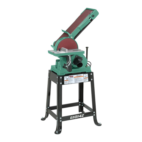
Combination sander
Hide thumbs
Also See for G1014Z:
- Owner's manual (68 pages) ,
- Manual update (30 pages) ,
- Parts list (5 pages)
Table of Contents
Advertisement
MODEL G1014Z/G1014ZX
COMBINATION SANDER
OWNER'S MANUAL
(For models manufactured since 07/17)
G1014Z
G1014ZX
COPYRIGHT © MARCH, 2009 BY GRIZZLY INDUSTRIAL, INC., REVISED OCTOBER, 2017 (AB)
WARNING: NO PORTION OF THIS MANUAL MAY BE REPRODUCED IN ANY SHAPE
OR FORM WITHOUT THE WRITTEN APPROVAL OF GRIZZLY INDUSTRIAL, INC.
(FOR MODELS MANUFACTURED SINCE 07/17) #BL11448 PRINTED IN TAIWAN
Advertisement
Table of Contents

Related Manuals for Grizzly G1014Z


Summary of Contents for Grizzly G1014Z
- Page 1 (For models manufactured since 07/17) G1014Z G1014ZX COPYRIGHT © MARCH, 2009 BY GRIZZLY INDUSTRIAL, INC., REVISED OCTOBER, 2017 (AB) WARNING: NO PORTION OF THIS MANUAL MAY BE REPRODUCED IN ANY SHAPE OR FORM WITHOUT THE WRITTEN APPROVAL OF GRIZZLY INDUSTRIAL, INC.
- Page 2 This manual provides critical safety instructions on the proper setup, operation, maintenance, and service of this machine/tool. Save this document, refer to it often, and use it to instruct other operators. Failure to read, understand and follow the instructions in this manual may result in fire or serious personal injury—including amputation, electrocution, or death.
-
Page 3: Table Of Contents
Machine Description ........2 Cleaning ............45 Identification ........... 3 Unpainted Cast Iron ........45 G1014Z Machine Data Sheet ......4 Lubrication ........... 45 G1014ZX Machine Data Sheet ...... 6 SECTION 7: SERVICE ........47 SECTION 1: SAFETY ........9 Troubleshooting ........... -
Page 4: Introduction
The work table and miter gauge can be adjusted for the desired angle. Model G1014Z/G1014ZX (Mfd. Since 07/17) -
Page 5: Identification
If you have never used this type of machine or equipment before, WE STRONGLY RECOMMEND that you read books, review industry trade magazines, or get formal training before beginning any projects. Regardless of the content in this section, Grizzly Industrial will not be held liable for accidents caused by lack of training. - Page 6 MACHINE DATA SHEET Customer Service #: (570) 546-9663 · To Order Call: (800) 523-4777 · Fax #: (800) 438-5901 MODEL G1014Z COMBINATION SANDER 6" X 48" BELT 9" DISC Z SERIES Product Dimensions: Weight................................117 lbs. Width (side-to-side) x Depth (front-to-back) x Height................30 x 24 x 56 in.
-
Page 7: G1014Zx Machine Data Sheet
Warranty ................................1 Year Approximate Assembly & Setup Time ...................... 1-1/2 Hours Serial Number Location ............ID Label on Front of Stand, Above Grizzly Nameplate ISO 9001 Factory ..............................No Certified by a Nationally Recognized Testing Laboratory (NRTL) ................No Awards ........................ - Page 8 The information contained herein is deemed accurate as of 10/19/2017 and represents our most recent product specifications. Model G1014ZX PAGE 1 OF 2 Due to our ongoing improvement efforts, this information may not accurately describe items previously purchased. Model G1014Z/G1014ZX (Mfd. Since 07/17)
- Page 9 The information contained herein is deemed accurate as of 10/19/2017 and represents our most recent product specifications. Model G1014ZX PAGE 2 OF 2 Due to our ongoing improvement efforts, this information may not accurately describe items previously purchased. Model G1014Z/G1014ZX (Mfd. Since 07/17)
-
Page 10: Section 1: Safety
Everyday ery. Never operate under the influence of drugs or eyeglasses are NOT approved safety glasses. alcohol, when tired, or when distracted. Model G1014Z/G1014ZX (Mfd. Since 07/17) - Page 11 EXPERIENCING DIFFICULTIES. If at any time debris. Make sure they are properly installed, you experience difficulties performing the intend- undamaged, and working correctly BEFORE ed operation, stop using the machine! Contact our operating machine. Technical Support at (570) 546-9663. Model G1014Z/G1014ZX (Mfd. Since 07/17)
-
Page 12: Safety For Belt And Disc Sanders
Failure to do so could result in serious per- risk of operator injury. If normal safety pre- cautions are overlooked or ignored, serious sonal injury, damage to equipment, or poor work results. personal injury may occur. -10- Model G1014Z/G1014ZX (Mfd. Since 07/17) -
Page 13: Section 2: Power Supply
Nominal Voltage ......220V/240V meets the specified circuit requirements. Cycle ............60 Hz Phase ........... Single-Phase Power Supply Circuit ......15 Amps Plug/Receptacle ......NEMA 6-15 -11- Model G1014Z/G1014ZX (Mfd. Since 07/17) -
Page 14: Extension Cords
The plug must only be inserted into a matching receptacle (see following figure) that is properly installed and grounded in accordance with all local codes and ordinances. -12- Model G1014Z/G1014ZX (Mfd. Since 07/17) -
Page 15: Section 3: Setup
Save the containers and all packing materials for possible inspection by the carrier or its agent. Otherwise, filing a freight claim can be difficult. When you are completely satisfied with the condi- tion of your shipment, inventory the contents. -13- Model G1014Z/G1014ZX (Mfd. Since 07/17) -
Page 16: Hardware Recognition Chart
Hardware Recognition Chart -14- Model G1014Z/G1014ZX (Mfd. Since 07/17) -
Page 17: G1014Z Inventory
G1014Z Inventory The following is a description of the main com- ponents shipped with the Model G1014Z. Lay the components out to inventory them. Note: If you can't find an item on this list, check the mounting location on the machine or examine the packaging materials carefully. -
Page 18: G1014Zx Inventory
B. Shelf ............1 Hardware (not shown) Figure 7. Cabinet inventory. • Hex Nuts 5/16"-18 (Cabinet) ......4 • Hex Bolts ⁄ "-18 x 1" (Cabinet) ....4 ⁄ " (Cabinet) ......4 • Flat Washers -16- Model G1014Z/G1014ZX (Mfd. Since 07/17) -
Page 19: Clean Up
Children and visitors may be seriously injured if unsuper- vised around this machine. Figure ??. T23692 Orange Power Degreaser. Lock entrances to the shop or disable start switch or power connection to prevent unsupervised use. -17- Model G1014Z/G1014ZX (Mfd. Since 07/17) -
Page 20: Mounting To Shop Floor
Bolting to Concrete Floors Mobile Base Lag shield anchors with lag bolts (Figure 8) and You can mount the Model G1014Z to the Model anchor studs are two popular methods for anchor- G7314 (shown below) or the G1014ZX to the ing an object to a concrete floor. -
Page 21: Mounting To Workbench
" flat washers, as shown in Figure 11. Finger tighten the fasteners for now. The Model G1014Z stand can be assembled with Note: Make sure the lip on the long braces the included feet or mounted directly to a concrete faces up. - Page 22 (8) ⁄ "-18 x ⁄ " carriage bolts, ⁄ "-18 hex nuts, and ⁄ " flat washers, then place the stand upright on its feet, as shown in Figure -20- Model G1014Z/G1014ZX (Mfd. Since 07/17)
-
Page 23: G1014Zx Cabinet Assembly
With the help of an assistant, lift the head- Place the stand flat on its side, but do not lay stock onto the stand (G1014Z) or the cabinet it down on the switch or door handle. (G1014ZX), and align the mounting holes in the sander unit and the stand or cabinet. - Page 24 Figure 23, to avoid the possibility of workpieces hitting the cover during sanding operations. Cover Plate "- " (Top View) Figure 23. Gap between plate and cover. -22- Model G1014Z/G1014ZX (Mfd. Since 07/17)
- Page 25 Figure 27. The rod should pro- trude about 6 ⁄ " from the side of the base. Table Support Figure 25. Installing sanding disc onto cast iron ⁄ " plate. Figure 27. Installing table support rod. -23- Model G1014Z/G1014ZX (Mfd. Since 07/17)
- Page 26 17. Adjust the miter gauge slot parallel with the sanding disc (refer to instructions on Page 51 for more details), then insert the miter Figure 29. Installing work table onto table gauge. support rod. -24- Model G1014Z/G1014ZX (Mfd. Since 07/17)
- Page 27 20. Move the quick release lever toward the motor, slide the sanding belt over the lever and onto the idler roller and drive rollers, then center the belt on the rollers (see Figure 33). -25- Model G1014Z/G1014ZX (Mfd. Since 07/17)
- Page 28 Test Run section on Page 30. Backstop Belt Platen " Clearance Motor Cord Frame Power Cord Figure 38. Correct clearance between backstop and belt. Figure 36. Motor cord connected to power cord. -26- Model G1014Z/G1014ZX (Mfd. Since 07/17)
-
Page 29: Calibrating Miter Gauge
Repeat Steps 1–5 in a similar manner to cali- main roller. brate the miter gauge to the belt if you set up the sander for vertical sanding. Tighten the tracking control knob lock nut. -27- Model G1014Z/G1014ZX (Mfd. Since 07/17) -
Page 30: Dust Collection
Consult an expert or purchase a good dust collection "how-to" book. The Model G1014Z/G1014ZX features a 2" dust port and a 2 ⁄ " dust port that can be connected to a dust collector or a dust collection system, using the components shown in Figure 41. -
Page 31: Power Connection
OFF (or the OFF button is pushed in) before connecting power. NOTICE The Model G1014Z/G1014ZX is prewired for Figure ??. Connecting power. 110V. If you plan to operate the machine at 220V, the motor must be rewired (see Page Disconnecting Power 5???). -
Page 32: Test Run
This safety feature noises or vibrations before operating the must work properly before proceeding with machine further. Always disconnect the regular operations. Call Tech Support for machine from power when investigating or help. correcting potential problems. -30- Model G1014Z/G1014ZX (Mfd. Since 07/17) -
Page 33: Section 4: Operations
Regardless of the content in this section, Paddle Switch Grizzly Industrial will not be held liable for accidents caused by lack of training. Figure 45. Paddle switch location on G1014Z. -31-... -
Page 34: Operation Overview
During a typical operation, the sander is turned details.) ON, and while holding the workpiece with both hands, the operator gradually eases the workpiece into the belt or the left side of the sanding disc. -32- Model G1014Z/G1014ZX (Mfd. Since 07/17) -
Page 35: Sanding Tips
While sanding, these objects can become dislodged and tear the sanding The Model G1014Z/G1014ZX uses a 6" x 48" belt. Always visually inspect your workpiece sanding belt and a 9" sanding disc. -
Page 36: Horizontal & Edge Sanding
Performing Horizontal or Edge Sanding Make sure the sanding belt is tensioned —if it is not already tight. Make sure the belt tracking is correctly set (see Tracking Belt on Page 41). Turn the sander ON. -34- Model G1014Z/G1014ZX (Mfd. Since 07/17) -
Page 37: Contour Sanding
Use extreme care to provide a safe distance between the belt Re-install the idler roller and sleeve guard. and any part of your body. -35- Model G1014Z/G1014ZX (Mfd. Since 07/17) -
Page 38: Disc Sanding
Note: To prevent burning the workpiece and over- loading the sanding disc, move the workpiece slowly back and forth from the left side of the sanding disc to the center. Figure 54. Example of 90° disc sanding. -36- Model G1014Z/G1014ZX (Mfd. Since 07/17) -
Page 39: Vertical Sanding
Top Rotation Nut Mounting Figure 58. Location of top rotation lock nut. Bracket Set Screws Bottom Rotation Nut Figure 61. Work table installed for vertical sanding. Figure 59. Location of bottom rotation lock nut. -37- Model G1014Z/G1014ZX (Mfd. Since 07/17) - Page 40 —If the distance is the same, no adjustments need to be made. 10. Tighten the mounting bracket set screws to secure the support rod. -38- Model G1014Z/G1014ZX (Mfd. Since 07/17)
- Page 41 See Figures 66–69 for examples of horizontal belt sanding. Figure 68. Example of vertical face and edge sanding. Figure 66. Example of end grain sanding. Figure 69. Example of sanding round workpiece in vertical position. -39- Model G1014Z/G1014ZX (Mfd. Since 07/17)
-
Page 42: Changing Sanding Belt
Some sanding belts are designed to sand in only one direction and will have a direction indi- cated on the back of the belt. The Model G1014Z/ G1014ZX is designed so that the sanding belt travels clockwise as viewed from the side with the quick release tension lever. -
Page 43: Tracking Belt
Changing Sanding Disc The aim of tracking the belt is to keep it centered on the rollers. The model G1014Z/G1014ZX accepts 9" diameter paper-backed pressure sensitive adhesive (PSA) To track the belt: discs (refer to Accessories on Page 42). Make sure the belt is properly pre-tracked To change the sanding disc: (refer to Pre-Tracking Belt on Page 27). -
Page 44: Section 5: Accessories
To minimize this risk, only install accessories recommended for this machine by Grizzly. T20451 NOTICE T20502 Refer to the newest copy of the Grizzly Catalog for other accessories available for T20503 this machine. T20452 PRO-STICK Abrasive Surface Cleaners ®... - Page 45 ". Has outrigger supports and a stable 4 wheel system. 600 lb. capacity. Weighs 32 lbs. Figure 79. G1029Z2P 2HP Dust Collector. Figure 77. D2260A SHOP FOX Mobile Base. ® www.grizzly.com 1-800-523-4777 order online at or call -43- Model G1014Z/G1014ZX (Mfd. Since 07/17)
-
Page 46: Section 6: Maintenance
SECTION 6: MAINTENANCE Cleaning Always disconnect power to the machine before Cleaning the Model G1014Z/G1014ZX is relatively performing maintenance. easy. Vacuum excess wood chips and sawdust, Failure to do this may and wipe off the remaining dust with a dry cloth. - Page 47 (see oil onto the shaft (see Figure 80). Move the work Figure 81). table back and forth to distribute the oil. Rocker Plate Figure 81. Rocker plate lubrication. Figure 80. Table support rod lubrication. -45- Model G1014Z/G1014ZX (Mfd. Since 07/17)
-
Page 48: Section 7: Service
8. Tighten disc hub or replace disc. 9. Motor bearings at fault. 9. Test by rotating shaft; rotational grinding/loose shaft requires bearing replacement. 10. Work table support rod rubbing on motor. 10. Adjust table support rod. -46- Model G1014Z/G1014ZX (Mfd. Since 07/17) -
Page 49: Machine Operation
2. Start workpiece on a trailing corner. Belt slips on rollers. 1. Quick release tension lever not engaged. 1. Engage quick release tension lever. 2. Adjust belt tension (see Page 49) 2. Belt tension not sufficient. -47- Model G1014Z/G1014ZX (Mfd. Since 07/17) -
Page 50: V-Belt Tension & Replacement
Re-install the cast iron plate onto the drive Pulley shaft and secure with the set screws, close and secure the pulley cover, then re-install the work table. Figure 82. Checking belt tension. -48- Model G1014Z/G1014ZX (Mfd. Since 07/17) -
Page 51: Sanding Belt Tension
(refer to Move the quick release tension lever toward Tracking Belt on Page 41 for further detail). the motor to tighten the sanding belt. -49- Model G1014Z/G1014ZX (Mfd. Since 07/17) -
Page 52: Pulley Alignment
—If there is a gap between the straightedge pointer, position the red scale pointer over the and one of the pulleys, that pulley needs to "0" mark on the angle scale, then re-tighten be adjusted. Proceed to Step 6. the screw. -50- Model G1014Z/G1014ZX (Mfd. Since 07/17) -
Page 53: Miter Slot-Disc Parallelism
Remove the miter gauge, then place a combi- nation square with the 90º square in the miter slot, as shown in Figure 89. Figure 89. Checking miter slot parallelism with sanding disc. -51- Model G1014Z/G1014ZX (Mfd. Since 07/17) -
Page 54: Section 8: Wiring
The photos and diagrams included in this section are best viewed in color. You can view these pages in color at www.grizzly.com. -52- Model G1014Z/G1014ZX (Mfd. Since 07/17) -
Page 55: G1014Z Wiring Diagram
G1014Z Wiring Diagram MOTOR (Prewired 110V) Ground Figure 90. G1014Z 110V motor wiring. MOTOR (Wired 220V) PADDLE SWITCH (viewed from behind) Ground (Wired 220V) 5-15 PLUG (Included) Ground 110V Neutral Figure 91. G1014Z switch wiring. Ground 220V 6-15 PLUG (As Recommended) -
Page 56: G1014Zx Wiring Diagram
Ground on the inside of junction box cover when rewiring your motor. 220V 6-15 PLUG (As Recommended) READ ELECTRICAL SAFETY -54- ON PAGE 52! Model G1014Z/G1014ZX (Mfd. Since 07/17) -
Page 57: Section 9: Parts
SECTION 9: PARTS G1014Z Main -55- Model G1014Z/G1014ZX (Mfd. Since 07/17) -
Page 58: G1014Z Main Parts List
JUNCTION BOX COVER P1014Z119 DUST PORT (ABS) 2-1/2" P1014Z044 LOCK KNOB 1/4-20 X 5/8 P1014Z120 MOTOR LABEL P1014Z045 PLASTIC WASHER 1/4-16 P1014Z126 LOCK KNOB 10-32 P1014Z046 FLAT WASHER #10 P1014Z127 FLAT WASHER #10 P1014Z049 STRAIN RELIEF -56- Model G1014Z/G1014ZX (Mfd. Since 07/17) -
Page 59: G1014Z Stand
MODEL # LABEL G1014Z P1014Z134 GLASSES/RESPIRATOR 2W X 3.3H P1014Z129 READ MANUAL 3.7W X 2H NS 7/05 P1014Z135 DISCONNECT 110V 2W X 3.3H P1014Z130 GRIZZLY GREEN TOUCH UP PAINT P1014Z136 ELECTRICITY LABEL P1014Z131 BLACK TOUCH UP PAINT -57- Model G1014Z/G1014ZX (Mfd. Since 07/17) -
Page 60: G1014Zx Main
G1014ZX Main -58- Model G1014Z/G1014ZX (Mfd. Since 07/17) -
Page 61: G1014Zx Main Parts List
P1014ZX043-5 S CAPACITOR COVER P1014ZX126 LOCK KNOB 10-32 43-6 P1014ZX043-6 JUNCTION BOX COVER P1014ZX127 FLAT WASHER #10 P1014ZX044 LOCK KNOB 1/4-20 X 5/8 P1014ZX128 PHLP HD SCR 10-24 X 3/8 P1014ZX045 PLASTIC WASHER 1/4-16 -59- Model G1014Z/G1014ZX (Mfd. Since 07/17) -
Page 62: G1014Zx Cabinet
GRIZZLY SAFETY PADDLE SWITCH P1014ZX076 SHELF P1014ZX055 PADDLE SWITCH KEY P1014ZX078 SWITCH HOUSING P1014ZX058 RUBBER FOOT P1014ZX079 ELECTRICITY LABEL P1014ZX060 MACHINE ID LABEL P1014ZX104 GRIZZLY NAMEPLATE- SMALL P1014ZX061 MODEL NUMBER LABEL P1014ZX118 TAP SCREW #5 X 3/8 -60- Model G1014Z/G1014ZX (Mfd. Since 07/17) -
Page 63: G1014Zx Labels
MUST maintain the original location and readability of the labels on the machine. If any label is removed or becomes unreadable, REPLACE that label before using the machine again. Contact Grizzly at (800) 523-4777 or www.grizzly.com to order new labels. -61-... - Page 64 -62- Model G1014Z/G1014ZX (Mfd. Since 07/17)
- Page 65 Would you recommend Grizzly Industrial to a friend? _____ Yes _____No Would you allow us to use your name as a reference for Grizzly customers in your area? Note: We never use names more than 3 times. _____ Yes _____No 10.
- Page 66 FOLD ALONG DOTTED LINE Place Stamp Here GRIZZLY INDUSTRIAL, INC. P.O. BOX 2069 BELLINGHAM, WA 98227-2069 FOLD ALONG DOTTED LINE Send a Grizzly Catalog to a friend: Name_______________________________ Street_______________________________ City______________State______Zip______ TAPE ALONG EDGES--PLEASE DO NOT STAPLE...
-
Page 67: Warranty And Returns
WARRANTY AND RETURNS Grizzly Industrial, Inc. warrants every product it sells for a period of 1 year to the original purchaser from the date of purchase. This warranty does not apply to defects due directly or indirectly to misuse, abuse, negligence, accidents, repairs or alterations or lack of maintenance.
Need help?
Do you have a question about the G1014Z and is the answer not in the manual?
Questions and answers