Grizzly G1014Z Owner's Manual
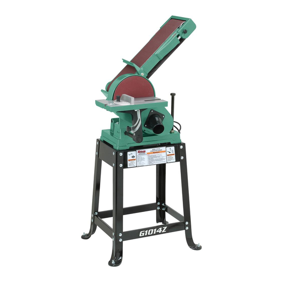
6" x 48" belt/9" disc combo sander
Hide thumbs
Also See for G1014Z:
- Owner's manual (68 pages) ,
- Manual update (30 pages) ,
- Parts list (5 pages)
Table of Contents
Advertisement
Quick Links
MODEL G1014Z/G1014ZX
6" X 48" BELT/9" DISC
COMBO SANDER
OWNER'S MANUAL
(For models manufactured since 08/22)
G1014Z
G1014ZX
COPYRIGHT © MARCH, 2009 BY GRIZZLY INDUSTRIAL, INC., REVISED AUGUST, 2022 (CS)
WARNING: NO PORTION OF THIS MANUAL MAY BE REPRODUCED IN ANY SHAPE
OR FORM WITHOUT THE WRITTEN APPROVAL OF GRIZZLY INDUSTRIAL, INC.
#BL11448 PRINTED IN TAIWAN
V3.08.22
Advertisement
Table of Contents

Related Manuals for Grizzly G1014Z


Summary of Contents for Grizzly G1014Z
- Page 1 (For models manufactured since 08/22) G1014Z G1014ZX COPYRIGHT © MARCH, 2009 BY GRIZZLY INDUSTRIAL, INC., REVISED AUGUST, 2022 (CS) WARNING: NO PORTION OF THIS MANUAL MAY BE REPRODUCED IN ANY SHAPE OR FORM WITHOUT THE WRITTEN APPROVAL OF GRIZZLY INDUSTRIAL, INC.
- Page 2 This manual provides critical safety instructions on the proper setup, operation, maintenance, and service of this machine/tool. Save this document, refer to it often, and use it to instruct other operators. Failure to read, understand and follow the instructions in this manual may result in fire or serious personal injury—including amputation, electrocution, or death.
-
Page 3: Table Of Contents
Identification ........... 3 Cleaning Sanding Belt/Disc ......44 Controls & Components ......... 4 Lubrication ........... 44 G1014Z Machine Data Sheet ......5 G1014ZX Machine Data Sheet ...... 7 SECTION 7: SERVICE ........45 Troubleshooting ........... 45 SECTION 1: SAFETY ........9 Squaring Work Table to Sanding Belt/Disc . -
Page 4: Introduction
The work table and miter gauge can be adjusted for the desired angle. Model G1014Z/G1014ZX (Mfd. Since 08/22) -
Page 5: Identification
Wear eye and ear protection. b) Support workpiece with miter gauge, backstop, or work table. c) Maintain ⁄ in. maximum clearance between table and sanding belt or disc. d) Avoid kickback by sanding in accordance with directional arrows. Model G1014Z/G1014ZX (Mfd. Since 08/22) -
Page 6: Controls & Components
Sanding Belt Controls Figure 1. Paddle switch location on G1014Z. Figure 4. Sanding belt controls. E. Sanding Belt Frame: Tilts between horizon- tal and vertical positions. -
Page 7: G1014Z Machine Data Sheet
MACHINE DATA SHEET Customer Service #: (570) 546-9663 · To Order Call: (800) 523-4777 · Fax #: (800) 438-5901 MODEL G1014Z 6" X 48" BELT/9" DISC Z SERIES COMBO SANDER Product Dimensions: Weight................................117 lbs. Width (side-to-side) x Depth (front-to-back) x Height................30 x 24 x 56 in. - Page 8 The information contained herein is deemed accurate as of 8/24/2022 and represents our most recent product specifications. Model G1014Z PAGE 2 OF 2 Due to our ongoing improvement efforts, this information may not accurately describe items previously purchased. Model G1014Z/G1014ZX (Mfd. Since 08/22)
-
Page 9: G1014Zx Machine Data Sheet
The information contained herein is deemed accurate as of 8/17/2022 and represents our most recent product specifications. Model G1014ZX PAGE 1 OF 2 Due to our ongoing improvement efforts, this information may not accurately describe items previously purchased. Model G1014Z/G1014ZX (Mfd. Since 08/22) - Page 10 The information contained herein is deemed accurate as of 8/17/2022 and represents our most recent product specifications. Model G1014ZX PAGE 2 OF 2 Due to our ongoing improvement efforts, this information may not accurately describe items previously purchased. Model G1014Z/G1014ZX (Mfd. Since 08/22)
-
Page 11: Section 1: Safety
Never operate under the influence of drugs or injury or blindness from flying particles. Everyday alcohol, when tired, or when distracted. eyeglasses are NOT approved safety glasses. Model G1014Z/G1014ZX (Mfd. Since 08/22) - Page 12 EXPERIENCING DIFFICULTIES. If at any time debris. Make sure they are properly installed, you experience difficulties performing the intend- undamaged, and working correctly BEFORE ed operation, stop using the machine! Contact our operating machine. Technical Support at (570) 546-9663. -10- Model G1014Z/G1014ZX (Mfd. Since 08/22)
-
Page 13: Additional Safety For Belt & Disc Sanders
To avoid these hazards, keep all control when sanding force is applied. guards in place and closed. DO NOT wear loose clothing, gloves, or jewelry, and tie back long hair. -11- Model G1014Z/G1014ZX (Mfd. Since 08/22) -
Page 14: Section 2: Power Supply
Nominal Voltage ..208V, 220V, 230V, 240V meets the specified circuit requirements. Cycle ............60 Hz Phase ........... Single-Phase Circuit Rating ........15 Amps Plug/Receptacle ......NEMA 6-15 -12- Model G1014Z/G1014ZX (Mfd. Since 08/22) - Page 15 The plug must only be inserted into a matching receptacle (see following figure) that is properly installed and grounded in accordance with all local codes and ordinances. -13- Model G1014Z/G1014ZX (Mfd. Since 08/22)
-
Page 16: Converting Voltage To 220V
Open the motor junction box, then loosen two available, NEMA standard 6-15 plug wir- wire nuts indicated in Figure 7. ing is provided beginning on Page 52. Remove These Wire Nuts Ground Figure 7. Motor prewired for 110V. -14- Model G1014Z/G1014ZX (Mfd. Since 08/22) -
Page 17: Section 3: Setup
Every shop environment is different. you are completely satisfied with the machine and Always consider safety first, as it applies have resolved any issues between Grizzly or the to your individual working conditions. Use shipping agent. You MUST have the original pack- this and other machinery with caution and aging to file a freight claim. -
Page 18: Hardware Recognition Chart
Hardware Recognition Chart -16- Model G1014Z/G1014ZX (Mfd. Since 08/22) -
Page 19: G1014Z Inventory
Figure 9. G1014Z sander unit. Box 1 (Figures 9–11) A. Sander Unit ..........1 B. Stand Legs ..........4 C. -
Page 20: G1014Zx Inventory
Thumb Knobs M5-.8 x 10 (Roller Guard) ..2 lost in packaging materials while unpack- • Flat Washers #10 (Roller Guard) ....2 ing or they are pre-installed at the factory. • Lock Washers #10 (Roller Guard) ....2 -18- Model G1014Z/G1014ZX (Mfd. Since 08/22) -
Page 21: Cleanup
Always test on a small, inconspicu- Lock entrances to the shop ous location first. or disable start switch or power connection to prevent unsupervised use. -19- Model G1014Z/G1014ZX (Mfd. Since 08/22) -
Page 22: Anchoring To Floor
(if accessed through the cabinet. applicable). For the Model G1014Z, begin assembly with Step Anchoring machinery to the floor prevents tipping or shifting and reduces vibration that may occur 1. For the Model G1014ZX, begin assembly with Step 11. - Page 23 Brace Short Upper Braces Figure 21. Stand assembled. Figure 19. Short upper and lower braces Final tighten all the fasteners on the stand. fastened to leg assembly. Tighten the hex nuts on the feet. -21- Model G1014Z/G1014ZX (Mfd. Since 08/22)
- Page 24 Figure 24. Leveling cabinet. 16. With the help of an assistant, lift the sanding Figure 22. Leveling stand. unit onto the stand (G1014Z) or the cabinet (G1014ZX), and align the mounting holes in 10. Proceed to Step 16. the sander unit and the stand or cabinet.
- Page 25 20. Loosen, but do not remove, the shaft set Cover screws on the cast iron plate so they are Plate backed out of the shaft hole and keyway (see Figure 28). "- " (Top View) Figure 30. Gap between plate and cover. -23- Model G1014Z/G1014ZX (Mfd. Since 08/22)
- Page 26 Figure 34. The rod should protrude about 6 ⁄ " from the side of the base. Table Support ⁄ " Figure 32. Installing sanding disc onto cast iron plate. Figure 34. Installing table support rod. -24- Model G1014Z/G1014ZX (Mfd. Since 08/22)
- Page 27 ⁄ " away from the sanding disc. 32. Square the table to the sanding disc (refer to instructions on Page 47 for more details). Figure 36. Installing work table onto table support rod. -25- Model G1014Z/G1014ZX (Mfd. Since 08/22)
- Page 28 (see Figure 41). Hex Nuts 6" Stud Idler Roller Guard Handle Thumb Knob Rocker Short Lever Figure 39. Quick release lever installed. Figure 41. Idler roller guard installed. -26- Model G1014Z/G1014ZX (Mfd. Since 08/22)
- Page 29 Test Run section on Page 30. Back Stop Belt Platen " Clearance Frame Motor Cord Figure 45. Correct clearance between back stop Power and belt. Cord Figure 43. Motor cord connected to power cord. -27- Model G1014Z/G1014ZX (Mfd. Since 08/22)
-
Page 30: Pre-Tracking Belt
Even Spaces on Both Sides Figure 47. Example of sanding belt centered on main roller. Tighten the tracking control knob lock nut. -28- Model G1014Z/G1014ZX (Mfd. Since 08/22) -
Page 31: Dust Collection
Consult an expert or purchase a good dust collection "how-to" book. The Model G1014Z/G1014ZX features a 2" dust port and a 2 ⁄ " dust port that can be connected to a dust collector or a dust collection system, using the components shown in Figure 48. -
Page 32: Test Run
This safety feature must work properly before proceeding with Moving sanding belts are dangerously abra- regular operations. Call Tech Support for sive. Use extreme caution when working help. near sanding surfaces. -30- Model G1014Z/G1014ZX (Mfd. Since 08/22) -
Page 33: Section 4: Operations
Regardless of the content in this sec- in this manual are easier to understand. tion, Grizzly Industrial will not be held liable for accidents caused by lack of training. Due to the generic nature of this overview, it is not intended to be an instructional guide. -
Page 34: Sanding Tips
Sanding Tips Choosing Sandpaper • Extend the life of the sandpaper by regularly The Model G1014Z/G1014ZX uses a 6" x 48" using PRO-STIK® abrasive belt cleaners sanding belt and a 9" sanding disc. Below is a (see Accessories on Page 42). -
Page 35: Workpiece Inspection
• Excessive Glue Finish: Sanding workpieces with excess glue or finish will load up the abrasive, reducing its usefulness and lifespan. -33- Model G1014Z/G1014ZX (Mfd. Since 08/22) - Page 36 Sanding surfaces can cause serious per- sonal injury if they come in contact with fingers, hands or other body parts. Use extreme care to provide a safe distance between the belt and any part of your body. -34- Model G1014Z/G1014ZX (Mfd. Since 08/22)
-
Page 37: Contour Sanding
Serious injury may result. You must re- install the idler roller guard before perform- ing edge or horizontal sanding operations. Figure 57. Example of 90° disc sanding. Install the idler roller guard. -35- Model G1014Z/G1014ZX (Mfd. Since 08/22) -
Page 38: Vertical Sanding
Note: To prevent burning the workpiece and over- loading the sanding disc, move the workpiece slowly back and forth from the left side of the sanding disc to the center. Figure 62. Location of bottom rotation lock nut. -36- Model G1014Z/G1014ZX (Mfd. Since 08/22) - Page 39 Note: To reduce the chance of vibration or sanding. rattling sounds, make sure the table support rod does not touch the motor. 10. Tighten the mounting bracket set screws to secure the support rod. -37- Model G1014Z/G1014ZX (Mfd. Since 08/22)
- Page 40 See Figures 68–71 for examples of horizontal belt sanding. Figure 71. Example of sanding round workpiece in vertical position. Figure 68. Example of end grain sanding. -38- Model G1014Z/G1014ZX (Mfd. Since 08/22)
-
Page 41: Changing Sanding Belt
Some sanding belts are designed to sand in only one direction and will have a direction indi- cated on the back of the belt. The Model G1014Z/ G1014ZX is designed so that the sanding belt travels clockwise as viewed from the side with the quick release tension lever. -
Page 42: Adjusting Sanding Belt Tension
Tracking Belt on Page 41 for further detail). Turn the eccentric shown in Figure 75 to tighten or loosen the belt. Eccentric Figure 75. Location of belt tension eccentric (belt removed for clarity). -40- Model G1014Z/G1014ZX (Mfd. Since 08/22) -
Page 43: Tracking Belt
Changing Sanding Disc The aim of tracking the belt is to keep it centered on the rollers. The model G1014Z/G1014ZX accepts 9" diameter paper-backed pressure sensitive adhesive (PSA) To track the belt: discs (refer to Accessories on Page 42). Pre-track the belt according to Pre-Tracking To change the sanding disc: Belt on Page 28. -
Page 44: Section 5: Accessories
Grit Model To reduce this risk, only install accessories 60 Grit ............D1321 recommended for this machine by Grizzly. 80 Grit ............D1322 100 Grit ............D1323 NOTICE 120 Grit ............D1324 150 Grit ............D1325 Refer to our website or latest catalog for 180 Grit ............ -
Page 45: Section 6: Maintenance
To reduce risk of shock or accidental startup, always disconnect machine from power before adjustments, Cleaning the Model G1014Z G1014ZX is relatively maintenance, or service. easy. Vacuum excess wood chips and sawdust, and wipe off the remaining dust with a dry cloth. -
Page 46: Cleaning Sanding Belt/Disc
Figure 83. Rocker plate lubrication. oil onto the shaft (see Figure 82). Move the work table back and forth to distribute the oil. -44- Model G1014Z/G1014ZX (Mfd. Since 08/22) -
Page 47: Section 7: Service
3. V-belt worn, loose, pulleys misaligned, or 3. Inspect/replace V-belt (Page 50). Realign pulleys if necessary (Page 50). belt slapping cover. 4. Pulley loose. 4. Secure pulley on shaft. 5. Motor mount loose/broken. 5. Tighten/replace. -45- Model G1014Z/G1014ZX (Mfd. Since 08/22) - Page 48 1. Clean (Page 44)/replace sanding belt (Page 39)/ Snake-shaped 1. Sanding belt/disc dirty/damaged. marks on disc (Page 41). workpiece. Glazed sanding 1. Sanding wet stock. 1. Only sand wood/ensure moisture is below 20% surfaces. (Page 33). -46- Model G1014Z/G1014ZX (Mfd. Since 08/22)
-
Page 49: Squaring Work Table To Sanding Belt/Disc
Loosen the Phillips head screw on the angle pointer, position the red scale pointer over the "0" mark on the angle scale, then re-tighten the screw. -47- Model G1014Z/G1014ZX (Mfd. Since 08/22) -
Page 50: Adjusting Miter Slot-Belt/Disc Parallelism
Page 37) that secure the work table arm to the work table and adjust the table so it is Retighten the screw that secures the angle approximately ⁄ " away from the sanding pointer. belt/disc across its entire length. -48- Model G1014Z/G1014ZX (Mfd. Since 08/22) -
Page 51: V-Belt Tension & Replacement
Re-install the cast iron plate onto the drive shaft and secure with the set screws, close Deflection and secure the pulley cover, then re-install Pulley the work table. Figure 87. Checking belt tension. -49- Model G1014Z/G1014ZX (Mfd. Since 08/22) -
Page 52: Pulley Alignment
Tighten the pulley set screw, re-install the To check and adjust pulley alignment: cast iron plate, close the pulley cover, then re-install the thumb knob and work table. DISCONNECT MACHINE FROM POWER! Remove the work table assembly and miter gauge. -50- Model G1014Z/G1014ZX (Mfd. Since 08/22) -
Page 53: Section 8: Wiring
Technical Support at (570) 546-9663. The photos and diagrams included in this section are best viewed in color. You can view these pages in color at www.grizzly.com. -51- Model G1014Z/G1014ZX (Mfd. Since 08/22) -
Page 54: G1014Z Wiring Diagram
G1014Z Wiring Diagram MOTOR (Prewired 110V) Ground Figure 91. G1014Z 110V motor wiring. MOTOR (Wired 220V) Ground Ground PADDLE SWITCH KEDU HY18 (Wired 220V) (viewed from behind) 5-15 PLUG (Included) Ground 110V Neutral Ground 220V 6-15 PLUG Figure 92. G1014Z switch wiring. -
Page 55: G1014Zx Wiring Diagram
PADDLE SWITCH KEDU HY18 (viewed from behind) Ground (Wired 220V) Ground 5-15 PLUG (Included) Ground 110V Neutral Ground 220V 6-15 PLUG (As Recommended) Figure 94. G1014ZX switch wiring. READ ELECTRICAL SAFETY -53- Model G1014Z/G1014ZX (Mfd. Since 08/22) ON PAGE 51! -
Page 56: Section 9: Parts
SECTION 9: PARTS We do our best to stock replacement parts when possible, but we cannot guarantee that all parts shown are available for purchase. Call (800) 523-4777 or visit www.grizzly.com/parts to check for availability. G1014Z Main 107 108 11 17... - Page 57 FLAT WASHER #10 P1014Z137 LOCK WASHER #10 P1014Z049 STRAIN RELIEF M14 TYPE-1 SNAP-IN P1014Z138 EXT TOOTH WASHER #10 P1014Z050 SWITCH PLATE BUY PARTS ONLINE AT GRIZZLY.COM! -55- Model G1014Z/G1014ZX (Mfd. Since 08/22) Scan QR code to visit our Parts Store.
-
Page 58: G1014Z Stand
P1014Z121 ENTANGLEMENT LABEL P1014Z131 TOUCH-UP PAINT, GRIZZLY BLACK P1014Z128 MODEL NUMBER LABEL P1014Z136 ELECTRICITY LABEL 129V2 P1014Z129V2 COMBO WARNING LABEL V2.08.22 BUY PARTS ONLINE AT GRIZZLY.COM! -56- Model G1014Z/G1014ZX (Mfd. Since 08/22) Scan QR code to visit our Parts Store. -
Page 59: G1014Zx Main
G1014ZX Main 107 108 11 17 15 7 114A 114A-1 127 43-1 43-3 43-5 43-6 43-2 43-4 BUY PARTS ONLINE AT GRIZZLY.COM! -57- Model G1014Z/G1014ZX (Mfd. Since 08/22) Scan QR code to visit our Parts Store. - Page 60 P1014ZX044 KNOB BOLT 1/4-20 X 3/4 P1014ZX128 PHLP HD SCR 10-24 X 3/8 P1014ZX045 PLASTIC WASHER 1/4-16 P1014ZX137 LOCK WASHER #10 BUY PARTS ONLINE AT GRIZZLY.COM! -58- Model G1014Z/G1014ZX (Mfd. Since 08/22) Scan QR code to visit our Parts Store.
-
Page 61: G1014Zx Cabinet
HEX NUT 10-24 P1014ZX076 SHELF P1014ZX053 SAFETY PADDLE SWITCH P1014ZX078 SWITCH HOUSING P1014ZX055 PADDLE SWITCH KEY P1014ZX118 TAP SCREW #5 X 3/8 BUY PARTS ONLINE AT GRIZZLY.COM! -59- Model G1014Z/G1014ZX (Mfd. Since 08/22) Scan QR code to visit our Parts Store. -
Page 62: G1014Zx Labels & Cosmetics
Safety labels help reduce the risk of serious injury caused by machine hazards. If any label comes off or becomes unreadable, the owner of this machine MUST replace it in the original location before resuming operations. For replacements, contact (800) 523-4777 or www.grizzly.com. BUY PARTS ONLINE AT GRIZZLY.COM! -60- Model G1014Z/G1014ZX (Mfd. -
Page 63: Warranty & Returns
WARRANTY & RETURNS Grizzly Industrial, Inc. warrants every product it sells for a period of 1 year to the original purchaser from the date of purchase. This warranty does not apply to defects due directly or indirectly to misuse, abuse, negligence, accidents, repairs or alterations or lack of maintenance.
Need help?
Do you have a question about the G1014Z and is the answer not in the manual?
Questions and answers