Grizzly G1014Z Manual Update
Combination sander
Hide thumbs
Also See for G1014Z:
- Owner's manual (68 pages) ,
- Parts list (5 pages) ,
- Owner's manual (64 pages)
Table of Contents
Advertisement
Quick Links
Download this manual
See also:
Owner's Manual
This update covers changes made to the machine after the owner's manual was printed. All page num-
ber references refer to the owner's manual for this machine. Keep this update with your owner's man-
ual for future reference. If you have questions, contact Tech Support at (570) 546-9663 or by email at
techsupport@grizzly.com.
What Changed?
We have added a sleeve guard to the sander to
help reduce the risk of entanglement. The sleeve
guard MUST be installed on the idler roller guard
using the lock knobs and flat washers, as shown
in Figure 1.
Install the idler roller guard and sleeve guard onto
the idler roller after belt tension and tracking are
properly set, as described on G1014Z Manual
Pages 12 & 13.
Idler Roller
Guard
Sleeve Guard
Figure 1. Installing sleeve guard.
WARNING: NO PORTION OF THIS MANUAL MAY BE REPRODUCED IN ANY SHAPE
OR FORM WITHOUT THE WRITTEN APPROVAL OF GRIZZLY INDUSTRIAL, INC.
#10 Flat
Washer
Lock Knob
COPYRIGHT © MARCH, 2008 BY GRIZZLY INDUSTRIAL, INC.
#BL10589 PRINTED IN TAIWAN
MODEL G1014Z/G1014ZX
COMBINATION SANDER
MANUAL UPDATE
Machine Inventory
The following items have been added. Refer to
the full manual for a description of the main inven-
tory.
Box Contents:
A. Sleeve Guard ............................................ 1
B. Lock Knobs ............................................... 2
C. Flat Washers #10 ....................................... 2
New Sleeve Guard Parts
114A-1
Figure 2. New sleeve guard parts.
REF
PART #
114A
P1014Z114A
114A-1 P1014Z114A-1 SLEEVE GUARD
126
P1014Z126
127
PW03
(See Page 6)
114A
127
126
127
126
DESCRIPTION
IDLER ROLLER GUARD V2.03.08
LOCK KNOB
FLAT WASHER #10
Qty
Advertisement
Table of Contents

Related Manuals for Grizzly G1014Z


Summary of Contents for Grizzly G1014Z
- Page 1 Figure 1. Installing sleeve guard. COPYRIGHT © MARCH, 2008 BY GRIZZLY INDUSTRIAL, INC. WARNING: NO PORTION OF THIS MANUAL MAY BE REPRODUCED IN ANY SHAPE OR FORM WITHOUT THE WRITTEN APPROVAL OF GRIZZLY INDUSTRIAL, INC. MODEL G1014Z/G1014ZX COMBINATION SANDER Machine Inventory The following items have been added.
- Page 2 G1014Z manual. COPYRIGHT © MAY, 2005. BY GRIZZLY INDUSTRIAL, INC. WARNING: NO PORTION OF THIS MANUAL MAY BE REPRODUCED IN ANY SHAPE OR FORM WITHOUT THE WRITTEN APPROVAL OF GRIZZLY INDUSTRIAL, INC. Combination Sander ⁄ " hex bolts and ⁄...
- Page 3 PLABEL-11 SAFETY GLASSES 2" X 3 5/16" All parts for the Model G1014ZX, except those shown above, are the same as the Model G1014Z. Therefore, please use the included Model G1014Z manual when ordering new parts for your machine, unless those parts are shown above.
- Page 4 COMBINATION SANDER MODEL G1014Z INSTRUCTION MANUAL COPYRIGHT © 1992 BY GRIZZLY INDUSTRIAL, INC. REG.# TX 3 360 514 WARNING: NO PORTION OF THIS MANUAL MAY BE REPRODUCED IN ANY SHAPE OR FORM WITHOUT THE WRITTEN APPROVAL OF GRIZZLY INDUSTRIAL, INC.
-
Page 6: Table Of Contents
TEST RUN ...16 HORIZONTAL SANDING ...16 CURVED SANDING ...17 DISC SANDING ...17 MAINTENANCE...18 LUBRICATION ...18 V-BELT ...18 TABLE ...18 GENERAL...18 CLOSURE ...19 MACHINE DATA ...20 PART BREAKDOWNS ...21-23 PART LIST ...24 WARRANTY AND RETURNS ...25 G1014Z Combination Sander Table Of Contents PAGE... -
Page 7: Safety
Everyday eyeglasses only have impact resistant lenses, they are NOT safety glasses. ⁄ '' maximum clearance between 16 A.W.G. 50ft 16 A.W.G. 100ft 14 A.W.G. 200ft 12 A.W.G. 300ft G1014Z Combination Sander... -
Page 8: Additional Safety Instructions For Sanders
Even if you have a reliable method of dust collection, use a dust mask or respirator when sanding, as well as eye and ear pro- tection. G1014Z Combination Sander 17. USE RECOMMENDED ACCESSORIES. Consult the owner’s manual for recommend- ed accessories. The use of improper acces- sories may cause risk of injury to persons. -
Page 9: Circuit Requirements
3-hole receptacles that accept the tool’s plug. FIgure 1. Repair or replace damaged or worn cord immedi- ately. Grounded Outlet Box Current Carrying Prongs Grounding Blade Is Longest Of the Three Blades Figure 1. G1014Z Combination Sander... -
Page 10: General Information
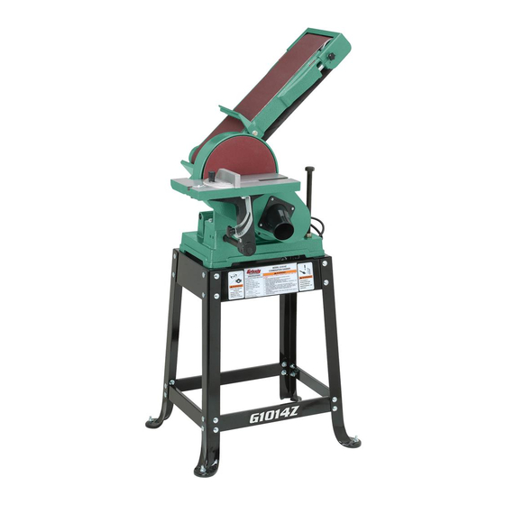
Grizzly’s commitment to customer satis- faction. The Model G1014Z is a combination 6" x 48" belt and 9" disc sander that is capable of a wide vari- ety of operations. The 6" wide belt enables you to sand large areas flat very quickly, and the 9"... -
Page 11: Unpacking
Unpacking The Model G1014Z Sander is shipped from the manufacturer in a carefully packed carton. If you discover the machine is damaged after you’ve signed for delivery, please call our Customer Service number immediately for advice. Save the containers and all packing materials for possible inspection by the carrier or its agent. -
Page 12: Clean Up
Clean up The work table and other unpainted parts of the Model G1014Z are coated with a waxy oil that protects them from corrosion during shipment. Remove the protective coating with mineral spir- its and cloth rags. Do not use gasoline or other petroleum based solvents because of their extremely low flash points. -
Page 13: Assembly
12mm open end wrench, regular screw- driver, Phillips screwdriver, and a 4mm Allen wrench. Stand The G1014Z Combination Sander stand is an open frame style. The four legs are connected with top and bottom cross braces. Attach Rubber Feet to base using the four ⁄... -
Page 14: Stand
Figure 3. Bolt the shorter upper and lower braces to one of the 2 stand sub-assemblies. Figure 4. Figure 4. G1014Z Combination Sander '' Carriage Bolts, Now attach the other sub-assembly to the ends of the short braces. Tighten down all the stand bolts at this time. -
Page 15: Sanding Unit
7. Make sure the Setscrew is lined up on the flat spot on the drive shaft. ⁄ " washers At this point, install the back stop, using the Hex Bolt and Washer as shown in Figure 7. Figure 7. Figure 8. G1014Z Combination Sander... - Page 16 Tighten the setscrews. Figure 10. Figure 10. G1014Z Combination Sander Now slide the working table assembly onto the support shaft and tighten the setscrews. Keep in mind that there should be a between the sanding disc and the table.
-
Page 17: Adjustments
Turn the machine on and off again quickly to see if the tracking has improved. If not, repeat step 1. If tracking is improved move to step 4. Now with the sander running, adjust the knob to fine tune the belt tracking. G1014Z Combination Sander ⁄ turn clock-... -
Page 18: Belt Tensioning
Normally steps 1-4 are done with the belt installed. Figure 14. G1014Z Combination Sander Use a large open end adjustable wrench and carefully rotate the eccentric, PN # 84A to increase or decrease tension. Remember: The belt should not sound like a drum when plucked. -
Page 19: Vertical Positioning
Simply remove the Table Support Shaft from the base and insert it into the mounting bracket behind the motor. The Bracket’s location is shown in Figure 17. -14- Figure 17. Figure 18. Setup for vertical sanding. G1014Z Combination Sander... -
Page 20: Changing Discs
Cast Iron Disc from the Motor Shaft because the Sanding Disc cannot be peeled off or the Cast Iron Disc requires cleaning. See page G1014Z Combination Sander Table tilt Loosen the table lock knob. Figure 19. The table can now be set to any angle between 0-45˚. -
Page 21: Operations
Figure 20. Depending on the length of the workpiece, use the back stop to prevent it from being ejected by the belt. If your workpiece is too long, simply remove the back stop. Figure 20. G1014Z Combination Sander... -
Page 22: Curved Sanding
To avoid excessive loading of the belt in one area, move workpiece slowly across entire surface of belt. Figure 21. Figure 21. G1014Z Combination Sander Disc Sanding Loosen table lock knob and tilt work table to desired angle. Tighten lock knob. -
Page 23: Maintenance
Department. Table The working table and other non-painted sur- faces on the Model G1014Z should be protected against rust and pitting. Wiping the sander clean after every use ensures that sawdust isn’t allowed to trap moisture against bare metal sur- faces. -
Page 24: Closure
Bellingham, Washington location using the address in the Introduction. The specifications, drawings, and photographs illustrated in this manual represent the Model G1014Z as supplied when the manual was prepared. However, due to Grizzly’s policy of continuous improvement, changes may be made at any time with no oblig- ation on the part of Grizzly. -
Page 25: Machine Data
GRIZZLY MODEL G1014Z COMBINATION SANDER Design Type ... Floor Model Overall Dimensions and Specifications: Base ...16 Height (Belt arm horizontal) ...40" Height (Belt arm vertical)...56" Width ...20" Length ...22" Table (Disc) ...6" x 11 Motor Shaft Size... Weight ...120 lbs. -
Page 26: Part Breakdowns
G1014Z Combination Sander -21-... - Page 27 -22- G1014Z Combination Sander...
- Page 28 G1014Z Combination Sander -23-...
-
Page 29: Part List
"-16 HEX NUT 10-24 HEX BOLT ⁄ ''-20 x FLAT WASHER LOWER BRACE, LONG LOWER BRACE, SHORT UPPER BRACE, LONG UPPER BRACE, SHORT IDLER ROLLER GUARD G1014Z Combination Sander ⁄ -18 x ⁄ ⁄ " ⁄ " ⁄ " ⁄... -
Page 30: Warranty And Returns
WARRANTY AND RETURNS Grizzly Industrial, Inc. warrants every product it sells for a period of 1 year to the original purchaser from the date of purchase. This warranty does not apply to defects due directly or indirectly to misuse, abuse, negligence, accidents, repairs or alterations or lack of maintenance.
Need help?
Do you have a question about the G1014Z and is the answer not in the manual?
Questions and answers