KEB COMBIVERT F6 Instructions For Use Manual
Installation f6 housing 6
Hide thumbs
Also See for COMBIVERT F6:
- Programming manual (544 pages) ,
- Reference manual (305 pages) ,
- Instructions for use manual (88 pages)
Table of Contents
Advertisement
Quick Links
Download this manual
See also:
Instruction Manual
Advertisement
Table of Contents

Subscribe to Our Youtube Channel
Related Manuals for KEB COMBIVERT F6


Summary of Contents for KEB COMBIVERT F6
- Page 1 COMBIVERT F6 INSTRUCTIONS FOR USE | INSTALLATION F6 HOUSING 6 Translation of the original manual Document 20114694 EN 01...
-
Page 3: Preface
PreFAce Preface The described hard- and software are developments of the KEB Automation KG. The enclosed documents correspond to conditions valid at printing. Misprint, mistakes and technical changes reserved. Signal words and symbols Certain operations can cause hazards during the installation, operation or thereafter. -
Page 4: Laws And Guidelines
The customer may use the instruction manual as well as further documents or parts from it for internal purposes. Copyrights are with KEB Automation KG and remain valid in its entirety. Other wordmarks or/and logos are trademarks (™) or registered trademarks (®) of their... -
Page 5: Table Of Contents
TAbLe OF cONTeNTS Table of contents Preface ..............................3 Signal words and symbols ......................3 More symbols ..........................3 Laws and guidelines ........................4 Warranty ............................4 Support ............................4 Copyright ............................4 Table of contents ........................... 5 List of Figures ............................8 List of Tables ............................9 Glossary .............................. - Page 6 3.3.4 Through-mount version water cooler IP54 ................. 41 3.3.5 Control cabinet installation ....................42 4 Installation and connection ........43 4.1 Overview of the cOMbIVerT F6 ....................43 4.2 connection of the power unit ....................... 46 4.2.1 Connection of the voltage supply ..................46 4.2.1.1 Terminal block X1A for 400V units ..................
- Page 7 TAbLe OF cONTeNTS 4.2.5.5 Motor cable cross-section ....................56 4.2.5.6 Interconnection of the motor .................... 56 4.2.5.8 Connection of the temperature monitoring and brake control (X1C) ....... 57 4.2.6 Connection and use of a braking resistor ................59 4.2.6.1 Installation instructions for side-mounted braking resistors ..........59 4.2.6.2 Terminal block X1A connection braking resistor ..............
-
Page 8: List Of Figures
LIST OF FIGUreS List of Figures Figure 1: Switch-off time t depending on the overload I/IN (OL) ............. 31 Figure 2: Overload characteristic in the lower speed range (OL2) Example unit size 23 ....33 Figure 3: Block diagram of the energy flow ..................36 Figure 4: Dimensions mounted version air cooler ................ -
Page 9: List Of Tables
LIST OF TAbLeS List of Tables Table 1: Part code..........................24 Table 2: Climatic ambient conditions ..................... 25 Table 3: Mechanical ambient conditions ..................26 Table 4: Chemical / mechanical active substances ............... 26 Table 5: Overvoltage........................27 Table 6: Electromagnetic compatibility ..................27 Table 7: Overview of the 400V unit data .................. -
Page 10: Glossary
Overcurrent Fieldbus system Overheat COMBIVERT KEB drive converters Overload COMBIVIS KEB start-up and parameterizing software OSSD Output signal swithching device; - an output signal that is checked in regu- DC current or voltage lar intervals on its shutdown. (safety Demineralized water, also referred to... - Page 11 GLOSSAry The security integrity level is a measure for quantifying the risk reduction. Term used in the safety technology (EN 61508 -1...7). Safety function „Safe stop 1“ in ac- cordance with IEC 61800-5-2 Synchronous serial interface for encoder Safety function „Safe Torque Off“ in accordance with IEC 61800-5-2 Incremental signal with an output voltage up to 5 V...
-
Page 12: Standards For Drive Converters / Control Cabinets
STANDArDS FOr DrIVe cONVerTerS / cONTrOL cAbINeTS Standards for drive converters / control cabinets Product standards that apply directly to the drive converter EN 61800-2 Adjustable speed electrical power drive systems - Part 2: General requirements - Rating specifications for low voltage adjustable frequency a.c. power drive systems (VDE 0160-102, IEC 61800-2) EN 61800-3 Speed-adjustable electrical drives. Part 3: EMC requirements and specific test methods (VDE 0160-103, IEC 61800-3) -
Page 13: Standards That Are Used In The Environment Of The Drive Converter
STANDArDS FOr DrIVe cONVerTerS / cONTrOL cAbINeTS EN 61000-4-4 Electromagnetic compatibility (EMC) - Part 4-4: Testing and measurement techniques - Electrical fast transient/burst immunity test (IEC 61000-4-4); German version EN 61000-4-4 EN 61000-4-5 Electromagnetic compatibility (EMC) - Part 4-5: Testing and measurement techniques - Surge immunity test (IEC 61000-4-5);... -
Page 14: Basic Safety Instructions
Hazards and risks through ignorance. ► Read the instruction manual ! ► Observe the safety and warning instructions ! ► If anything is unclear, please contact KEB Automation KG ! 1.1 Target group This instruction manual is determined exclusively for electrical personnel. Electrical per- sonnel for the purpose of this instruction manual must have the following qualifications: •... -
Page 15: Installation
bASIc SAFeTy INSTrUcTIONS Drive converters contain electrostatic sensitive components. ► Avoid contact. ► Wear ESD-protective clothing. Do not store drive converters • in the environment of aggressive and/or conductive liquids or gases. • with direct sunlight. • outside the specified environmental conditions. 1.3 Installation DANGer Do not operate in an explosive environment! ►... -
Page 16: Electrical Connection
bASIc SAFeTy INSTrUcTIONS 1.4 electrical connection DANGer Voltage at the terminals and in the device ! Danger to life due to electric shock ! ► Never work on the open device or never touch exposed parts. ► For any work on the unit switch off the supply voltage and secure it against switching on. -
Page 17: Emc-Compatible Installation
Accordng to EN 60204-1 it is permissible to disconnect already tested com- ponents. Drive converters of the KEB Automation KG are delivered ex works voltage tested to 100% according to product standard. 1.4.3 Insulation measurement An insulation measurement (in accordance with chapter 18.3) with DC... -
Page 18: Start-Up And Operation
Never touch terminals, busbars or cable ends. Observe the following instructions if the drive converter for more than one year was not in operation before start-up. https://www.keb.de/fileadmin/media/Manuals/knowledge/04_techinfo/00_ general/ti_format_capacitors_0400_0001_gbr.pdf Switching at the output Switching between motor and drive converter is prohibited for single drives during op- eration as this may trigger the protection gear of the device. -
Page 19: Maintenance
For applications that require cyclic switching on and off of the drive converter, maintain an off-time of at least 5 min after the last switch on. If you require shorter cycle times please contact KEB Automation KG. Short-circuit proof The drive converters are conditional short-circuit proof. After resetting the internal pro- tection devices, the function as directed is guaranteed. -
Page 20: Disposal
Drive converters with safety function are limited to a service life of 20 years. Then the devices must be replaced. Drive converters of the KEB Automation KG are professional, electronic devices exclu- sively for further industrial processing (so-called B2B devices). Thus the marking does not occur with the symbol of the crossed-out wheeled bin, but by the word mark and the date of manufacture. -
Page 22: Product Description
Technical data and information for connection conditions shall be taken from the type plate and from the instruction manual and must be strictly observed. The used semiconductors and components of the KEB Automation KG are developed and dimensioned for the use in industrial products. -
Page 23: Product Features
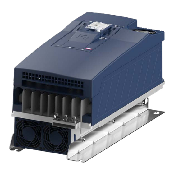
COMBIVERT F6 Power range: 45...90 kW / 400 V Housing size: The COMBIVERT F6 is characterized by the following features: • Operation of three-phase asynchronous motors and three-phase synchronous motors, in operating modes open-loop or closed-loop with and without speed feedback •... -
Page 24: Part Code
Multi encoder interface, CAN and STO on board, ® 3 EtherCAT or VARAN on board ® 1 Series COMBIVERT F6 Inverter size 12…32 Table 1: Part code EtherCAT® is registered trademark and patented technology, licensed by Beckhoff Automation GmbH, Germany... -
Page 25: Technical Data
3 Technical Data 3.1 Operating conditions 3.1.1 climatic ambient conditions Storage Standard Particularities Surrounding temperature EN 60721-3-1 -25…55 °C Relative humidity 5…95 % (without condensation) EN 60721-3-1 Storage height – – Max. 3000 m above sea level Transport Standard Particularities Surrounding temperature EN 60721-3-2 -25…70 °C... -
Page 26: Mechanical Ambient Conditions
3.1.2 Mechanical ambient conditions Storage Standard Particularities Vibration limits EN 60721-3-1 Covered by 3M4 Transport Standard Particularities Vibration limits EN 60721-3-2 Frequency 200…500 Hz, acceleration 15 m/s² Shock limit values EN 60721-3-2 Free drop from 0.25 m Operation Standard Particularities Frequency 5…9 Hz, amplitude 6 mm EN 60721-3-3 Frequency 9…200 Hz, acceleration 10 m/s²... -
Page 27: Electrical Operating Conditions
3.1.4 electrical operating conditions 3.1.4.1 Overvoltage Overvoltage Standard Particularities EN 61800-5-1 Overvoltage category – EN 60664-1 Table 5: Overvoltage 3.1.4.2 Electromagnetic compatibility The indicated values are only valid for units with external filter. eMc emitted interference Standard Particularities EN 55011 The specified value is only achieved in connec- Conducted emissions EN 61800-3 tion with an appropriate special external filter. Also see =>... -
Page 28: Unit Data Of The 400V Units
3.2 Unit data of the 400V units 3.2.1 Overview The technical data are for 2/4-pole standard motors. With other pole numbers the drive converter must be dimensioned onto the rated motor current. Contact KEB for special or medium frequency motors. Inverter size... -
Page 29: Voltage And Frequencies
UNIT DATA OF THe 400V UNITS 4) A detailed description of the derating => 3.2.4. 5) Observe limitations => 3.2.3.1. 3.2.2 Voltage and frequencies rated input voltage N_ac Rated mains voltage (USA) N_UL_ac Input voltage range 280...550 IN_ac Input phases Mains frequency / Hz 50 / 60... -
Page 30: Input And Output Currents/ Overload
UNIT DATA OF THe 400V UNITS 3.2.3 Input and output currents/ overload Inverter size Rated input current @ U = 400V N_ac Rated input current @ U = 480V N_UL_ac IN_UL Rated input current @ U = 565V N_dc IN_dc Rated input current @ U = 680V N_UL_dc... -
Page 31: Overload Characteristic (Ol)
UNIT DATA OF THe 400V UNITS 3.2.3.1 Overload characteristic (OL) All drive converters of housing size 6 can be operated at rated switching frequency with an utilization of 150 % for 60 s. Restrictions: • The thermal design of the heat sink is based on the rated current and the maximum surrounding temperature. -
Page 32: Frequency-Dependent Maximum Current (Ol2)
UNIT DATA OF THe 400V UNITS 3.2.3.2 Frequency-dependent maximum current (OL2) The characteristics of the maximum currents for a switching frequency which are de- pending on the output frequency are different for each drive converter, but the following general rules apply are generally applicable: •... -
Page 33: Figure 2: Overload Characteristic In The Lower Speed Range (Ol2) Example Unit Size 23
UNIT DATA OF THe 400V UNITS The following tables indicate the permissible maximum current for 3 output frequency values (0 Hz, 6 Hz, 25 Hz). In between there is a linear interpolation. Unit size 23 is represented exemplary. 200% 180% 160% 140% 120%... -
Page 34: Switching Frequency And Temperature
UNIT DATA OF THe 400V UNITS Inverter size 23 (4 kHz) Output frequency / Hz Frequency-dependent maximum current @ f = 2 kHz Frequency-dependent maximum current @ f = 4 kHz Frequency-dependent maximum current @ f = 8 kHz Frequency-dependent maximum current @ f = 16 kHz Table 15: Frequency-dependent maximum current for unit size 23... -
Page 35: Power Dissipation At Nominal Operating
UNIT DATA OF THe 400V UNITS 3.2.5 Power dissipation at nominal operating Inverter size Power dissipation at nominal operating 1356 1194 1650 1580 Power dissipation at DC supply 1158 1350 1208 D_dc Table 18: Power dissipation of the 400V units 1) Rated operation corresponds to U = 400 V;... -
Page 36: Dc Link / Braking Transistor Function Gtr7
UNIT DATA OF THe 400V UNITS 3.2.7 Dc link / braking transistor function GTr7 Activation of the braking transistor function In order to use the braking transistor (GTR7), the function must be activated with parameter "is30 braking transistor function". For more information => F6 Programming manual Inverter size DC link rated voltage @ U = 400V... -
Page 37: Fan
UNIT DATA OF THe 400V UNITS 3.2.8 Fan Inverter size Number Interior fan variable-speed Number Heat sink fan variable-speed The fans are speed-adjustable. They are automatically controlled to high or low speed, depending on the software settings. ATTENTION Destruction of the fan! ►... -
Page 38: Dimensions And Weights
DIMeNSIONS AND WeIGHTS 3.3 Dimensions and weights 3.3.1 Mounted version air cooler 23,2 Housing size 21.5 kg Weight Figure 4: Dimensions mounted version air cooler... -
Page 39: Mounted Version Water Cooler
DIMeNSIONS AND WeIGHTS 3.3.2 Mounted version water cooler 501,8 23,2 Housing size 18.1 kg Weight Figure 5: Dimensions mounted version water cooler... -
Page 40: Through-Mount Version Air Cooler Ip54
DIMeNSIONS AND WeIGHTS 3.3.3 Through-mount version air cooler IP54 5 x 101 = (505) 10x101=(505) 11,5 Housing size 20.6 kg Weight Figure 6: Dimensions through-mount version air cooler IP54 IP54 zone: Heat sink underneath the mounting plate. For proper installation, the enclosed seal (60F6T45-0002) must be installed between heat sink and housing (e.g. -
Page 41: Through-Mount Version Water Cooler Ip54
DIMeNSIONS AND WeIGHTS 3.3.4 Through-mount version water cooler IP54 31,5 (5 x 101) = 505 (5 x 101) = 505 11,5 16 x 7,5 Housing size 17.3 kg Weight Figure 7: Dimensions through-mount version water cooler IP54 IP54 zone: Heat sink underneath the mounting plate. For proper installation, the enclosed seal (60F6T45-0002) must be installed between heat sink and housing (e.g. -
Page 42: Control Cabinet Installation
DIMeNSIONS AND WeIGHTS 3.3.5 control cabinet installation Power loss for the control cabinet dimension => 3.2.5 A lower value can be used here depending on the operating mode/load. Dimen- Mounting distances Distance in mm Distance in inch sion Distance to preceding elements in the control cab- inet door. -
Page 43: Installation And Connection
OVerVIeW OF THe cOMbIVerT F6 4 Installation and connection 4.1 Overview of the cOMbIVerT F6 Housing size 6 Name Description Shield clambs for shielded control 1 / 5 lines LEDs (see the manual for the con- trol unit chapter „Overview“) FS: At K control board without function. -
Page 44: Figure 11: F6 Housing Size 6 Front View
OVerVIeW OF THe cOMbIVerT F6 Housing size 6 Name Description Interior fan Protective earth; at connection to protective earth each terminal may be assigned only once Power circuit terminals for: • mains input • Braking resistor • DC supply •... -
Page 45: Figure 12: F6 Housing Size 6 Rear View With K Control Board
F6 housing size 6 rear view with K control board Further views can be found in the respective control board manual. Instruction manual COMBIVERT F6 control board K https://www.keb.de/fileadmin/media/Manuals/dr/ma_dr_f6-cu-k- inst-20144795_en.pdf Instructions for use COMBIVERT F6 control board A https://www.keb.de/fileadmin/media/Manuals/dr/ma_dr_f6-cu-a- inst-20118593_en.pdf... -
Page 46: Connection Of The Power Unit
► Never exchange mains input and motor output! 4.2.1 connection of the voltage supply The COMBIVERT F6 housing size 6 can be sup- plied from the mains via terminals L1, L2 and L3. The use of the DC terminals for feed-in is permitted only with external precharging. -
Page 47: Terminal Block X1A For 400V Units
cONNecTION OF THe POWer UNIT 4.2.1.1 Terminal block X1A for 400V units Terminal connec- Tightening Name Function tion torque Mains connection 3-phase DC connection, Connection for intercon- nected operation Connection for braking resistor (between + and 8 mm stud for M8 10...15 Nm cable lugs 88...132 lb inch... -
Page 48: Protective Earth And Function Earth
cONNecTION OF THe POWer UNIT 4.2.2 Protective earth and function earth NOTE Protective and functional earth must not be connected to the same terminal. 4.2.2.1 Protective earth The protective earth (PE) serves for electrical safety particularly personal protection in error case. cAUTION electric shock due to incorrect dimensioning! ►... -
Page 49: Ac Connection
EN 61800- ⑤ systems HF filter for IT systems ⑥ KEB COMBIVERT Figure 16: Connection of the mains supply 400 Vac / 3-phase 4.2.3.2 Supply line The conductor cross-section of the supply line is determined by the following factors: • input current of the drive converter •... -
Page 50: Note On Hard Power Systems
„hard“ power systems or when under permanent drive load (continuous duty). For continuous duty (S1) drives with a medium duty of > 60 %, KEB provided the use of mains chokes with a terminal voltage U of 4%. -
Page 51: Dc Connection
4.2.4.1 Connection at DC voltage supply Legend DC voltage 400 / 480 V class: 390...780 Vdc Type aR Fuses Pay attention to the permissible voltage range ! max. occurring voltage 840 Vdc KEB COMBIVERT Figure 17: Connection at DC voltage supply... -
Page 52: Terminal Block X1A Dc Connection
cONNecTION OF THe POWer UNIT 4.2.4.2 Terminal block X1A DC connection Terminal connec- Tightening Name Function tion torque DC connection, 8 mm stud for M8 10...15 Nm +, - connection for intercon- cable lugs 88...132 lb inch nected operation Figure 18: Terminal block X1A DC connection M8 cable lugs with the following dimensions can be used for connections L1, L2, L3, U, V, W:... -
Page 53: Connection Of The Motor
OF THe POWer UNIT 4.2.5 connection of the motor 4.2.5.1 Wiring of the motor Legend KEB COMBIVERT Apply motor cable, shielding on both sides over a large surface on the bare metallic frame or mount- TA1 TA2 ing plate (remove paint if necessary) Three-phase motor Temperature monitoring (optional) =>... -
Page 54: Terminal Block X1A Motor Connection
cONNecTION OF THe POWer UNIT 4.2.5.2 Terminal block X1A motor connection Terminal connec- Tightening Name Function tion torque 8 mm stud for M8 10...15 Nm U, V, W Motor connection cable lugs 88...132 lb inch Figure 20: Terminal block X1A motor connection M8 cable lugs with the following dimensions can be used for connections L1, L2, L3, U, V, W: •... -
Page 55: Selection Of The Motor Cable
The maximum motor line length is depending on the capacity of the motor cable as well as on the EMC emitted interference. External measures must be taken here (e.g. the use of a line filter). The following information is valid for the operation under rated con- ditions and the use of KEB listed filters under chapter => 4.3.1! Max. motor cable length shielded max. leakage... -
Page 56: Motor Cable Length For Parallel Operation Of Motors
cONNecTION OF THe POWer UNIT 4.2.5.4 Motor cable length for parallel operation of motors The resulting motor cable length for parallel operation of motors, or parallel installation with multiple cables arises from the following formula: resulting motor cable length = ∑single line length x √Number of motor lines 4.2.5.5 Motor cable cross-section The cable cross-section of the motor cable depends on the real effective value of the motor current, the line length, the type of the used cable (observe the manufacturer's specifications) as well as the ambient conditions such as bundling and temperature. -
Page 57: Connection Of The Temperature Monitoring And Brake Control (X1C)
OF THe POWer UNIT 4.2.5.8 Connection of the temperature monitoring and brake control (X1C) A switchable KTY84/PTC evaluation is implemented in the COMBIVERT F6. The de- sired operating mode can be adjusted via the software.If the evaluation is not required, it must be deactivated via software (=>... -
Page 58: Figure 24: Connection Of A Kty Sensor
cONNecTION OF THe POWer UNIT KTY sensors are polarized semiconductors and must be operated in forward direction! To this connect the anode to TA1 and the cathode to TA2! Non-observance leads to incorrect measurements in the upper temperature range. A protection of the motor winding is then no longer guaranteed. -
Page 59: Connection And Use Of A Braking Resistor
► Cover hot surfaces safe-to-touch. ► Before touching, check the surface. ► If necessary, attach warning signs on the system. 4.2.6.1 Installation instructions for side-mounted braking resistors Instructions for the installation of intrinsically safe braking resistors => https://www.keb.de/fileadmin/media/Manuals/dr/ma_dr_ Chapter „Installation in- safe-braking-resistors-20106652_gbr.pdf structions“. -
Page 60: Terminal Block X1A Connection Braking Resistor
cONNecTION OF THe POWer UNIT 4.2.6.2 Terminal block X1A connection braking resistor Terminal connec- Tightening Name Function tion torque Connection for brak- 8 mm stud for M8 10...15 Nm +, R ing resistor (between cable lugs 88...132 lb inch + and R) Figure 25: Terminal block X1A connection braking resistor M8 cable lugs with the following dimensions can be used for connections L1,... -
Page 61: Wiring Of An Intrinsically Safe Braking Resistor
Intrinsically safe braking resisitors behave in error case such as a safety fuse. They interrupt themselves without fire risk. More information about intrinsically safe braking resistors => https://www.keb.de/fileadmin/media/Manuals/dr/ma_dr_safe-brak- ing-resistors-20106652_en.pdf 4.2.6.4 Using a non-intrinsically safe braking resistor Using a non-intrinsically safe braking resistor with extend- ed temperature monitoring =>... -
Page 62: Accessories
400 V 24E6T60-3000 23Z1B04-1000 24E6T60-3000 24Z1B04-1000 Table 22: Filters and chokes The specified filters and chokes are designed for rated operation. 4.3.2 Side-mounted braking resistors Technical data and design about intrinsically safe braking resistors => https://www.keb.de/fileadmin/media/Manuals/dr/ma_dr_ safe-braking-resistors-20106652_en.pdf Technical data and design about non-intrinsically safe braking resistors => https://www.keb.de/fileadmin/media/Manuals/ dr/ma_dr_braking-resistors-20116737_en.pdf... -
Page 63: Installation And Operation Of Water-Cooled Devices
HeAT SINk AND OPerATING PreSSUre 5 Installation and Operation of Water-cooled Devices The use of water-cooled KEB COMBIVERT drive converters is offered, because there are process-caused coolants available with some applications. However, the following instructions must be observed. 5.1 Heat sink and operating pressure... -
Page 64: Requirements For The Coolant
reqUIreMeNTS FOr THe cOOLANT 5.3 requirements for the coolant The requirements for the coolant depend on the ambient conditions as well as the used cooling system. General requirements for the coolant: requirement Description Standards Corrosion protection according to 12502-1...5, water treatment and use of ma- terials in cooling systems according to VGB R 455 P The VGB cooling water directive (VGB-R 455 P) contains instructions about com-... - Page 65 Pipe diameter inside: 7...8 mm Figure 27: Open pipe ends for the connection of the cooling system Straight screw-in connection, cutting rings and union nuts (e.g. from Parker Er- meto) can be used for the connection of the cooling system. KEB recommends the use of a flow switch in order to monitor the flow in the cooling system.
- Page 66 cOOLANT TeMPerATUre AND MOISTUre cONDeNSATION 5.5 coolant temperature and moisture condensation The inlet temperature may not exceed 40°C. The maximum heat sink temperature is 90°C or 95°C depending on the power unit and overload capacity => 3.2.4. To ensure a safe operation the coolant output temperature must be 10K below this temperature. Due to high air humidity and high temperatures it can lead to moisture condensation.
- Page 67 cOOLANT TeMPerATUre AND MOISTUre cONDeNSATION Temperature control The cooling can be switched on by means of a pneumatic valve or a solenoid valve, which is connected uptream by a relay. The valves for temperature control must be used in the flow line of the cooling circuit in order to avoid pressure surges. All conventional valves can be used. Make sure that the valves are working properly and do not clamp. ATTENTION Destruction of the heat sink at storage of water-cooled devices! Observe the following points when storing water-cooled devices...
- Page 68 cOOLANT HeATING 5.6 coolant heating The following graphic shows examples of measurements with different flow rates. ΔT [K] 5 l/min 10 l/min 20 l/min 30 l/min 40 l/min 50 l/min 100 l/min Pv [kW] Figure 28: Coolant heating depending on power loss and flow rate with water 5.7 Typical pressure drop l/min 12,5 Figure 29:...
-
Page 69: Certification
cerTIFIcATION 6 Certification 6.1 Certification 6.1.1 ce-Marking CE marked drive converters and servo drives were developed and manufactured to comply with the regulations of the Low-Voltage Directive. The harmonized standards of the series EN 61800-5-1 EN 61800-3 were used. For more information about the EU declarations of conformity => 6.2... -
Page 70: Ul Certifications
6.1.2 UL certifications Acceptance according to UL is marked at KEB drive converters with the adjacent logo on the nameplate. To be conform according to UL for use on the North American and Canadian Market the following additionally instructions must be observed (original text of the UL-File): •... -
Page 71: Further Information And Documentation
6.2 Further information and documentation You find supplementary manuals and instructions for the download under "http://www.keb.de > Service & Downloads > Downloads". General instructions • EMC and safety instructions • Manuals for control boards, safety modules, fieldbus modules, etc. Instruction and information for construction and development • Input fuses in accordance with UL • Programming manual for control and power unit •... -
Page 72: Revision History
reVISION HISTOry 7 revision History Version Date Description 2016-04 Prototype 2016-09 Pre-series 2017-11 Serie, new CI, water cooling, UL certification included... - Page 73 Tel: +55 16 31161294 E-Mail: roberto.arias@keb.de Room 1709, 415 Missy 2000 725 Su Seo Dong Gangnam Gu 135- 757 Seoul Republic of Korea Tel: +82 2 6253 6771 Fax: +82 2 6253 6770 E-Mail: vb.korea@keb.de Société Française KEB SASU France Z.I.
Need help?
Do you have a question about the COMBIVERT F6 and is the answer not in the manual?
Questions and answers