Table of Contents
Advertisement
Advertisement
Chapters
Table of Contents

Subscribe to Our Youtube Channel
Related Manuals for Mitsubishi Electric MDS-D-SPJ3


Summary of Contents for Mitsubishi Electric MDS-D-SPJ3
- Page 2 MELDAS is a registered trademark of Mitsubishi Electric Corporation. Other company and product names that appear in this manual are trademarks or registered trademarks of their respective companies.
-
Page 4: Introduction
Introduction Thank you for selecting the Mitsubishi numerical control unit. This instruction manual describes the handling and caution points for using this AC servo/spindle.Incorrect handling may lead to unforeseen accidents, so always read this instruction manual thoroughly to ensure correct usage. In order to confirm if all function specifications described in this manual are applicable, refer to the specifications for each CNC. - Page 6 Precautions for safety Please read this manual and auxiliary documents before starting installation, operation, maintenance or inspection to ensure correct usage. Thoroughly understand the device, safety information and precautions before starting operation. The safety precautions in this instruction manual are ranked as "WARNING" and "CAUTION". DANGER When there is a potential risk of fatal or serious injuries if handling is mistaken.
- Page 7 The signs indicating prohibited and mandatory matters are explained below. Indicates a prohibited matter. For example, "Fire Prohibited" is indicated as Indicates a mandatory matter. For example, grounding is indicated as The meaning of each pictorial sign is as follows. CAUTION CAUTION rotated CAUTION HOT...
- Page 8 WARNING 1. Electric shock prevention Do not open the front cover while the power is ON or during operation. Failure to observe this could lead to electric shocks. Do not operate the unit with the front cover removed. The high voltage terminals and charged sections will be exposed, and can cause electric shocks.
- Page 9 2. Injury prevention In the system where the optical communication with CNC is executed, do not see directly the light generated from CN1A/CN1B connector of drive unit or the end of cable. When the light gets into eye, you may feel something is wrong for eye. (The light source of optical communication corresponds to class1 defined in JISC6802 or IEC60825-1.) The linear servomotor, direct-drive motor and built-in IPM spindle motor uses permanent magnets in the rotor, so observe the following precautions.
- Page 10 CAUTION 1. Fire prevention Install the units, motors and regenerative resistor on non-combustible material. Direct installation on combustible material or near combustible materials could lead to fires. Always install a circuit protector and contactor on the servo drive unit power input as explained in this manual.
- Page 11 CAUTION 3. Various precautions Observe the following precautions. Incorrect handling of the unit could lead to faults, injuries and electric shocks, etc. (1) Transportation and installation Correctly transport the product according to its weight. Use the motor's hanging bolts only when transporting the motor. Do not transport the machine when the motor is installed on the machine.
- Page 12 CAUTION Store and use the units under the following environment conditions. Environment Unit Motor Operation: 0 to 55°C(with no freezing), Operation: 0 to 40°C(with no freezing), Ambient temperature Storage / Transportation: -15°C to 70°C Storage: -15°C to 70°C (Note2) (with no freezing) (with no freezing) Operation: 90%RH or less Operation: 80%RH or less...
- Page 13 CAUTION Always connect the motor to the drive unit's output terminals (U, V, W). Do not directly connect a commercial power supply to the servomotor. Failure to observe this could result in a fault. When using an inductive load such as a relay, always connect a diode as a noise measure parallel to the load.
- Page 14 CAUTION (4) Usage methods In abnormal state, install an external emergency stop circuit so that the operation can be stopped and power shut off immediately. Turn the power OFF immediately if smoke, abnormal noise or odors are generated from the unit or motor.
- Page 15 CAUTION (5) Troubleshooting If a hazardous situation is predicted during power failure or product trouble, use a servomotor with magnetic brakes or install an external brake mechanism. Use a double circuit configuration that allows the Shut off with NC brake Shut off with the servomotor control PLC output.
- Page 16 CAUTION (8) Transportation The unit and motor are precision parts and must be handled carefully. According to a United Nations Advisory, the battery unit and battery must be transported according to the rules set forth by the International Civil Aviation Organization (ICAO), International Air Transportation Association (IATA), International Maritime Organization (IMO), and United States Department of Transportation (DOT), etc.
- Page 18 Treatment of waste The following two laws will apply when disposing of this product. Considerations must be made to each law. The following laws are in effect in Japan. Thus, when using this product overseas, the local laws will have a priority.
- Page 20 This symbol mark is according to the directive 2006/66/EC Article 20 Information for end- users and Annex II. Your MITSUBISHI ELECTRIC product is designed and manufactured with high quality materials and components which can be recycled and/or reused. This symbol means that batteries and accumulators, at their end-of-life, should be disposed of separately from your household waste.
-
Page 22: Table Of Contents
Contents 1 Introduction ..............1 - 1 1-1 Servo/spindle drive system configuration ..................1 - 2 1-1-1 System configuration ........................ 1 - 2 1-2 Explanation of type ........................... 1 - 3 1-2-1 Servomotor type ........................1 - 3 1-2-2 Servo drive unit type......................... 1 - 4 1-2-3 Spindle motor type........................ - Page 23 3-2-7 High-speed synchronous tapping control (OMR-DD control) ........... 3 - 9 3-2-8 Dual feedback control......................3 - 10 3-2-9 HAS control ..........................3 - 10 3-2-10 Control loop gain changeover....................3 - 10 3-2-11 Spindle output stabilizing control ..................3 - 11 3-2-12 High-response spindle acceleration/deceleration function ...........
- Page 24 5 Dedicated Options ............. 5 - 1 5-1 Servo options............................ 5 - 2 5-1-1 Battery option ........................... 5 - 4 5-1-2 Ball screw side detector (OSA105-ET2)................... 5 - 9 5-1-3 Machine side detector ......................5 - 11 5-2 Spindle options ..........................5 - 15 5-2-1 Spindle side ABZ pulse output detector (OSE-1024 Series) ..........
- Page 25 Appendix 1 Cable and Connector Specifications ...........Appendix 1 - 1 Appendix 1-1 Selection of cable....................Appendix 1 - 2 Appendix 1-1-1 Cable wire and assembly ................. Appendix 1 - 2 Appendix 1-2 Cable connection diagram ................Appendix 1 - 4 Appendix 1-2-1 Battery cable.....................
- Page 26 Appendix 4-5 Measures for various cables................Appendix 4 - 5 Appendix 4-5-1 Measures for wiring in panel..............Appendix 4 - 5 Appendix 4-5-2 Measures for shield treatment ..............Appendix 4 - 5 Appendix 4-5-3 Servo/spindle motor power cable ............. Appendix 4 - 6 Appendix 4-5-4 Servo/spindle motor feedback cable ............
- Page 28 Outline for MDS-D-SVJ3/SPJ3 Series 2-6-2 Connection of the grounding cable 2-7 Connection of regenerative resistor Instruction Manual (IB-1500193-D) 2-7-1 Standard built-in regenerative resistor (Only for MDS-D-SVJ3) 1 Installation 2-7-2 External option regenerative resistor 2-8 Wiring of the peripheral control 1-1 Installation of servomotor 2-8-1 Wiring of the Input/output circuit 1-1-1 Environmental conditions 2-8-2 Wiring of the contactor control...
- Page 29 4-5-2 Speed loop delay compensation 7 Maintenance 4-5-3 Dual feedback control 7-1 Periodic inspections 4-6 Settings for emergency stop 7-1-1 Inspections 4-6-1 Deceleration control 7-1-2 Cleaning of spindle motor 4-6-2 Vertical axis drop prevention control 7-2 Service parts 4-6-3 Vertical axis pull-up control 7-3 Adding and replacing units and parts 4-7 Protective functions 7-3-1 Replacing the drive unit...
- Page 30 Appendix 3-8 Precautions in balancing of motor with Appendix 4 Compliance to EC Directives Appendix 4-1 Compliance to EC Directives Appendix 4-1-1 European EC Directives Appendix 4-1-2 Cautions for EC Directive compliance Appendix 5 EMC Installation Guidelines Appendix 5-1 Introduction Appendix 5-2 EMC instructions Appendix 5-3 EMC measures Appendix 5-4 Measures for panel structure...
-
Page 32: Servo/Spindle Drive System Configuration
章 付録 Introduction Contents 1-1 Servo/spindle drive system configuration ............. 1 - 2 1-1-1 System configuration ................1 - 2 1-2 Explanation of type ..................1 - 3 1-2-1 Servomotor type ................... 1 - 3 1-2-2 Servo drive unit type ................1 - 4 1-2-3 Spindle motor type................ - Page 33 (Note) Prepared Prepared Prepared by user Prepared by user by user by user Spindle Servo drive unit drive unit (MDS SVJ3) (MDS-D-SPJ3) Option L1 L2 L3 L1 L2 L3 Regene- Regene- rative rative resistor resistor CN1A CN1A From NC CN1B...
-
Page 34: Explanation Of Type
4000 r/min 176 SQ. (2) Magnetic brakes None Mitsubishi Electric Corporation Nagoya Works 3.5 kW 3500 r/min 176 SQ. Mitsubishi Electric Dalian Industrial Products Co., Ltd. (MDI) Sy mbol Magnetic brake 1.2 kW 3000 r/min 130 SQ. None None 2.2 kW 3000 r/min 130 SQ. -
Page 35: Servo Drive Unit Type
MITSUBISHI CNC 1 Introduction 1-2-2 Servo drive unit type Output MITSUBISHI TYPE Type Applicable standard Input/output conditions Software No. Manual No. Serial No. Rating nameplate ① MDS-D-SVJ3- Compatible HF □ HF-KP □ (1) Unit Type motor type MDS-D-SVJ3- Stall torque Unit width 12.0 13.7... -
Page 36: Spindle Motor Type
MDS-D-SVJ3/SPJ3 Series Specifications Manual 1-2 Explanation of type 1-2-3 Spindle motor type MITSUBISHI ELECTRIC AC SPINDLE MOTOR MODEL SJ−D7. 5/100−01 kW r/min A max S1 CONT 5. 5 1500−6000 35 3. 3 10000 18 S2 30min 7. 5 1500−6000... -
Page 37: Tool Spindle Motor Type
2.2 kW 2000 r/min 130 SQ. 3.0 kW 2000 r/min 176 SQ. < Combination with spindle drive unit > Unit Type Compatible HF □ HF-KP □ MDS-D-SPJ3- motor type Stall torque 10.5 14.3 0.64 Unit width (N・m) Rated output 075NA 60mm 0.75kW... -
Page 38: Spindle Drive Unit Type
1-2-5 Spindle drive unit type Output MITSUBISHI TYPE Type Applicable standard Input/output conditions Software No. Manual No. Serial No. Rating nameplate MDS-D-SPJ3- (1) Capacity Symbol Rated output Unit w idth 075NA 0.75kW 60mm w ide 22NA 2.2kW 90mm w ide 37NA 3.7kW... - Page 39 1 - 8...
-
Page 40: Specifications
章 付録 Specifications Contents 2-1 Servomotor ....................2 - 2 2-1-1 Specifications list .................. 2 - 2 2-1-2 Torque characteristics ................2 - 5 2-2 Spindle motor....................2 - 7 2-2-1 Specifications ..................2 - 7 2-2-2 Output characteristics ................. 2 - 13 2-3 Tool spindle motor .................. -
Page 41: Servomotor
MITSUBISHI CNC 2 Specifications 2-1 Servomotor 2-1-1 Specifications list < HF Series > HF Series ABS specifications: HF □ -A51 / -A48 Servomotor type HF75 HF105 HF54 HF104 HF154 HF224 HF204 HF354 Compatible servo drive MDS-D-SVJ3- 07NA 07NA 07NA 10NA 20NA 20NA 20NA... - Page 42 MDS-D-SVJ3/SPJ3 Series Specifications Manual 2-1 Servomotor < HF Series > HF Series ABS specifications: HF □ -A51 / -A48 Servomotor type HF123 HF223 HF303 HF142 HF302 Compatible servo drive MDS-D-SVJ3- 10NA 10NA 20NA 10NA 10NA unit type Rated output [kW] Rated current [A] 10.7 Continuous...
- Page 43 MITSUBISHI CNC 2 Specifications < HF-KP Series > HF-KP Series Servomotor type Absolute position standard HF-KP13J-S17 HF-KP23JW04-S6 HF-KP43JW04-S6 HF-KP73JW04-S6 Compatible servo drive MDS-D-SVJ3- 03NA 03NA 04NA 07NA unit type Rated output [kW] 0.75 Rated current [A] 0.77 Continuous characteris- Rated torque [N•m] 0.32 0.64 tics...
-
Page 44: Torque Characteristics
MDS-D-SVJ3/SPJ3 Series Specifications Manual 2-1 Servomotor 2-1-2 Torque characteristics < HF Series > [ HF75 ] [ HF105 ] Short time operation range Short time operation range Continuous operation range Continuous operation range 2000 4000 5000 2000 4000 5000 Rotation speed [r/min] Rotation speed [r/min] [ HF54 ] [ HF104 ]... - Page 45 MITSUBISHI CNC 2 Specifications < HF Series > [ HF142 ] [ HF302 ] Short time operation range Short time operation range Continuous operation range Continuous operation range 1000 2000 1000 2000 Rotation speed [r/min] Rotation speed [r/min] < HF-KP Series > [ HF-KP13J-S17 ] [ HF-KP23JW04-S6 ] [ HF-KP43JW04-S6 ]...
-
Page 46: Spindle Motor
2-2 Spindle motor 2-2 Spindle motor 2-2-1 Specifications < SJ-D Series (Standard) > Spindle motor type SJ-D3.7/100-01 SJ-D5.5/100-01 SJ-D7.5/100-01 SJ-D11/80-01 Compatible spindle drive MDS-D-SPJ3- 37NA 55NA 75NA 110NA unit type Continuous rating [kW] Output capacity Short time rating [kW] (15-minute rating) - Page 47 MITSUBISHI CNC 2 Specifications < SJ-DJ Series (Compact & lightweight specifications) > Spindle motor type SJ-DJ5.5/100-01 SJ-DJ7.5/100-01 SJ-DJ11/100-01 Compatible spindle drive MDS-D-SPJ3- 55NA 75NA 110NA unit type Continuous rating [kW] Output capacity Short time rating [kW] (25%ED rating) (15-minute rating)
- Page 48 MDS-D-SVJ3/SPJ3 Series Specifications Manual 2-2 Spindle motor < SJ-V Series (Standard) > Spindle motor type SJ-VL0.75-01T SJ-VL1.5-01T SJ-V2.2-01T SJ-V3.7-01T SJ-V5.5-01ZT Compatible spindle drive MDS-D-SPJ3- 075NA 22NA 22NA 37NA 55NA unit type Continuous rating [kW] 0.75 Output 0.75 capacity Short time rating [kW]...
- Page 49 MITSUBISHI CNC 2 Specifications < SJ-V Series (Standard) > Spindle motor type SJ-V7.5-01ZT SJ-V7.5-03ZT SJ-V11-01T SJ-V11-01ZT Compatible spindle drive MDS-D-SPJ3- 75NA 110NA 110NA 110NA unit type Continuous rating [kW] Output capacity Short time rating [kW] (30-minute rating) (30-minute rating) (15-minute rating)
- Page 50 MDS-D-SVJ3/SPJ3 Series Specifications Manual 2-2 Spindle motor < SJ-V Series (High-speed) > Spindle motor type SJ-VL2.2-02ZT Compatible spindle drive MDS-D-SPJ3- 37NA unit type Output Continuous rating [kW] capacity Short time rating [kW] 2.2 (15-minute rating) Power facility capacity [kVA] Base rotation speed [r/min]...
- Page 51 MITSUBISHI CNC 2 Specifications < SJ-VL Series (Low-inertia) > Spindle motor type SJ-VL11-05FZT-S01 SJ-VL11-10FZT SJ-VL11-07ZT SJ-VL11-07ZT Compatible spindle drive MDS-D-SPJ3- 110NA 110NA 110NA 110NA unit type Continuous rating [kW] Output capacity Short time rating [kW] (10-minute rating) (15-minute rating) (30-minute rating)
-
Page 52: Output Characteristics
MDS-D-SVJ3/SPJ3 Series Specifications Manual 2-2 Spindle motor 2-2-2 Output characteristics < SJ-D Series (Standard)> [ SJ-D3.7/100-01 ] [ SJ-D5.5/100-01 ] [ SJ-D7.5/100-01 ] 30-minute rating 30-minute rating Continuous rating 15-minute rating Continuous rating Continuous rating 1500 6000 10000 1500 6000 10000 1500 6000... - Page 53 MITSUBISHI CNC 2 Specifications < SJ-V Series (Standard)> [ SJ-VL0.75-01T ] [ SJ-VL1.5-01T ] [ SJ-V2.2-01T ] 10-minute rating 0.75 0.75 10-minute rating Continuous rating 15-minute rating Continuous rating Continuous rating 1500 6000 10000 1500 6000 10000 1500 6000 10000 Rotation speed [r/min] Rotation speed [r/min] Rotation speed [r/min]...
- Page 54 MDS-D-SVJ3/SPJ3 Series Specifications Manual 2-2 Spindle motor < SJ-VL Series (Low-inertia)> [ SJ-VL11-05FZT-S01 ] [ SJ-VL11-10FZT ] [ SJ-VL11-07ZT ] During During acceleration/deceleration acceleration/deceleration During acceleration/deceleration 30-minute rating Continuous rating 15-minute rating 10-minute rating Continuous rating Continuous rating 5000 6000 12000 0 1500 2200...
-
Page 55: Tool Spindle Motor
HF-KP Series Tool spindle motor type HF-KP □ -W09 HF-KP46 HF-KP56 HF-KP96 Compatible spindle 075NA 075NA 075NA MDS-D-SPJ3- drive unit type Rated output [kW] Continuous charac- Rated current [A] teristics 0.64 0.80 1.43 Rated torque [N•m] Power facility capacity [kVA]... - Page 56 HF Series HF □ -A48 Tool spindle motor type HF75 HF105 HF54 HF104 HF154 HF224 HF204 HF123 HF223 HF303 Compatible spindle drive MDS-D-SPJ3- 075NA 075NA 075NA 22NA 37NA 37NA 37NA 075NA 22NA 37NA unit type Rated output [kW] 0.75 Continuous...
-
Page 57: Output Characteristics
MITSUBISHI CNC 2 Specifications 2-3-2 Output characteristics < HF-KP Series > [ HF-KP46JW09 ] [ HF-KP56JW09 ] [ HF-KP96JW09 ] Short time operation range Short time operation range Short time operation range Continuous operation range Continuous operation range Continuous operation range 2000 4000 6000... - Page 58 MDS-D-SVJ3/SPJ3 Series Specifications Manual 2-3 Tool spindle motor < HF Series > [ HF75 ] [ HF105 ] Short time operation range Short time operation range Continuous operation range Continuous operation range 2000 4000 2000 4000 Rotation speed [r/min] Rotation speed [r/min] [ HF54 ] [ HF104 ] [ HF154 ]...
-
Page 59: Drive Unit
MITSUBISHI CNC 2 Specifications 2-4 Drive unit 2-4-1 Installation environment conditions Common installation environment conditions for servo and spindle are shown below. Operation: 0 to 55 ℃ (with no freezing), Storage / Transportation: -15 ℃ to 70 ℃ (with no freezing) Ambient temperature Operation: 90%RH or less (with no dew condensation) Ambient humidity... -
Page 60: Spindle Drive Unit
MDS-D-SVJ3/SPJ3 Series Specifications Manual 2-4 Drive unit 2-4-3 Spindle drive unit Spindle drive unit MDS-D-SPJ3 Series Spindle drive unit type 075NA 22NA 37NA 55NA 75NA 110NA MDS-D-SPJ3- Rated output [kW] 0.75 11.0 Rated voltage [V] 200AC (50Hz) / 200 to 230AC (60Hz) Tolerable fluctuation: between +10% and -15%... -
Page 61: Unit Outline Dimension Drawing
MITSUBISHI CNC 2 Specifications 2-4-4 Unit outline dimension drawing Unit [mm] 2 - 22... -
Page 62: Explanation Of Each Part
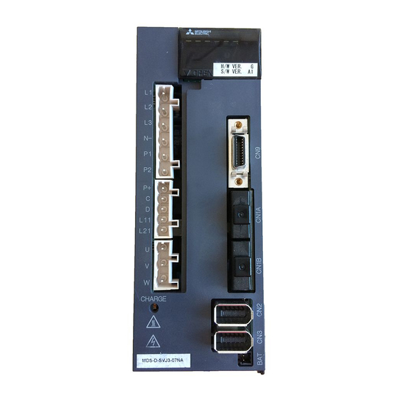
MDS-D-SVJ3/SPJ3 Series Specifications Manual 2-4 Drive unit 2-4-5 Explanation of each part (1) Explanation of each servo drive unit part (10) (10) (10) (11) (11) (12) (12) (12) (11) (13) (13) (13) MDS-D-SVJ3-03NA/04NA/07NA MDS-D-SVJ3-10NA/20NA MDS-D-SVJ3-35NA The connector and terminal block layout may differ according to the unit being used. Refer to each unit outline drawing for details. - Page 63 (10) (11) (11) (11) (10) (12) (12) (12) MDS-D-SPJ3-075NA MDS-D-SPJ3-22NA MDS-D-SPJ3-37NA The connector and terminal block layout may differ according to the unit being used. Refer to each unit outline drawing for details. <Each part name> Name Description Screw size Unit status indication LED Axis No.
- Page 64 MDS-D-SVJ3/SPJ3 Series Specifications Manual 2-4 Drive unit (3) Explanation of each spindle drive unit (5.5 to 11kW) part (10) (11) MDS-D-SPJ3-55NA/75NA (10) (11) MDS-D-SPJ3-110NA The connector and terminal block layout may differ according to the unit being used. Refer to each unit outline drawing for details.
- Page 65 2 - 26...
-
Page 66: Function Specifications
章 付録 Function Specifications Contents 3-3-1 Jitter compensation ....... 3 - 12 Function specifications list ........3 - 2 3-1 Base functions ..........3 - 4 3-3-2 Notch filter ..........3 - 12 3-1-1 Full closed loop control......3 - 4 3-3-3 Adaptive tracking-type notch filter .. -
Page 67: Function Specifications List
MITSUBISHI CNC 3 Function Specifications Function specifications list <Servo specification> MDS-DM- MDS-D- MDS-DH- MDS-DM- SPV2F/3F MDS-D- Item V1/V2 V1/V2 MDS-DM- SVJ3 SPV2/3 ● ● ● (Note2) ● 1-1 Full closed loop control ● ● ● ● ● 1-2 Position command synchronous control Base ●... - Page 68 MDS-D-SVJ3/SPJ3 Series Specifications Manual <Spindle specifications> MDS-DM- MDS-D- MDS-DH- MDS-D- SPV2F/3F MDS-D- Item MDS-DM- SPJ3 SPV2/3 ● ● ● ● ● 1-5 Spindle's continuous position loop control ● ● ● 1-6 Coil changeover control ● ● ● ● ● 1-7 Gear changeover control ●...
-
Page 69: Base Functions
MITSUBISHI CNC 3 Function Specifications 3-1 Base functions 3-1-1 Full closed loop control The servo control is all closed loop control using the detector's feedback. "Full closed loop control" is the system that directly detects the machine position using a linear scale, whereas the general "semi-closed loop"... -
Page 70: Speed Command Synchronous Control
MDS-D-SVJ3/SPJ3 Series Specifications Manual 3-1 Base functions 3-1-3 Speed command synchronous control This is one of the controls which enable two servo motors to drive the same axis. This is also called "Speed tandem control". The same position command is issued to the 2-axis servo control, and the control is carried out according to each axis' position and speed feedbacks. -
Page 71: Spindle's Continuous Position Loop Control
MITSUBISHI CNC 3 Function Specifications 3-1-5 Spindle's continuous position loop control Under this control, position loop control is always applied to spindle, including when speed command is issued (in cutting). There is no need for control changeover nor zero point return during orientation and C axis control changeover. -
Page 72: Coil Changeover Control
MDS-D-SVJ3/SPJ3 Series Specifications Manual 3-1 Base functions 3-1-6 Coil changeover control A signal output from the spindle drive unit controls the changeover of the low-speed and high-speed specification coils in a spindle motor. The drive unit automatically outputs the coil changeover sequence in accordance with the motor speed. 3-1-7 Gear changeover control This function enables a spindle motor to perform both high-speed light cutting and low-speed heavy cutting by changing the gear ratio between the motor and spindle. -
Page 73: Servo/Spindle Control Functions
MITSUBISHI CNC 3 Function Specifications 3-2 Servo/Spindle control functions 3-2-1 Torque limit function This control suppresses the motor output torque with the parameter values (SV013, SV014). This function is used for stopper positioning control and stopper reference position establishment, by switching the two setting values. -
Page 74: Speed Loop Pid Changeover Control
MDS-D-SVJ3/SPJ3 Series Specifications Manual 3-2 Servo/Spindle control functions 3-2-4 Speed loop PID changeover control This function is used under full-closed loop control. Normally, machine-end position tracking delays compared with the motor-end position. Under full-closed position loop control, machine-end position is used for position feedback. Therefore, the motor-end position tends to advance too much, which may cause overshooting of the machine-end position. -
Page 75: Dual Feedback Control
MITSUBISHI CNC 3 Function Specifications 3-2-8 Dual feedback control This function is used under full-closed loop control. When a linear scale is used, the machine-end position, such as a table, is directly detected, which may render the position loop control unstable. With this control, however, high-frequency components are eliminated from the machine-end feedback signals, which will lead to stable control. -
Page 76: Spindle Output Stabilizing Control
MDS-D-SVJ3/SPJ3 Series Specifications Manual 3-2 Servo/Spindle control functions 3-2-11 Spindle output stabilizing control Spindle motor's torque characteristic is suppressed due to voltage saturation in the high-speed rotation range, therefore the current control responsiveness significantly degrades, which may cause excessive current. With this control, however, the current and flux commands are compensated to avoid the voltage saturation so that the current control responsiveness will not degrade. -
Page 77: Compensation Controls
MITSUBISHI CNC 3 Function Specifications 3-3 Compensation controls 3-3-1 Jitter compensation The load inertia becomes much smaller than usual if the motor position enters the machine backlash when the motor is stopped. Because this means that an extremely large VGN1 is set for the load inertia, vibration may occur. Jitter compensation can suppress the vibration that occurs at the motor stop by ignoring the backlash amount of speed feedback pulses when the speed feedback polarity changes. -
Page 78: Overshooting Compensation
MDS-D-SVJ3/SPJ3 Series Specifications Manual 3-3 Compensation controls 3-3-4 Overshooting compensation The phenomenon when the machine position goes past or exceeds the command during feed stopping is called overshooting. In OVS compensation, the overshooting is suppressed by subtracting the torque command set in the parameters when the motor stops. -
Page 79: Lost Motion Compensation Type 2
MITSUBISHI CNC 3 Function Specifications 3-3-6 Lost motion compensation type 2 Servo motor always drives the machine opposing to the frictional force, and the torque which is required to oppose the friction during the axis movement is outputted by I control (Integral control) of the speed loop PI control. -
Page 80: Lost Motion Compensation Type 4
MDS-D-SVJ3/SPJ3 Series Specifications Manual 3-3 Compensation controls 3-3-8 Lost motion compensation type 4 When the difference between static and dynamic friction is large, the friction torque changes sharply at the inversion of the travel direction. When the lost motion type 4 is used together with the type 2 or type 3, the acute change of the friction torque is compensated so that the path accuracy at the travel direction inversion can be enhanced. -
Page 81: Protection Function
MITSUBISHI CNC 3 Function Specifications 3-4 Protection function 3-4-1 Deceleration control at emergency stop When an emergency stop (including NC failure, servo alarm) occurs, the motor will decelerate following the set time constant while maintaining the READY ON state. READY will turn OFF and the dynamic brakes will function after stopping. The deceleration stop can be executed at a shorter distance than the dynamic brakes. -
Page 82: Collision Detection Function
MDS-D-SVJ3/SPJ3 Series Specifications Manual 3-4 Protection function 3-4-4 Collision detection function Collision detection function quickly detects a collision of the motor shaft, and decelerates and stops the motor. This suppresses the generation of an excessive torque in the machine tool, and helps to prevent an abnormal state from occurring.Impact at a collision will not be prevented by using this collision detection function, so this function does not necessarily guarantee that the machine tool will not be damaged or that the machine accuracy will be maintained after a collision. -
Page 83: Sequence Functions
MITSUBISHI CNC 3 Function Specifications 3-5 Sequence functions 3-5-1 Contactor control function With this function, the contactor ON/OFF command is output from the power supply unit (or servo/spindle drive unit for integrated type) based on the judgement as to whether it is in emergency stop, emergency stop cancel, spindle deceleration and stop or vertical axis drop prevention control, etc. -
Page 84: Specified Speed Output
MDS-D-SVJ3/SPJ3 Series Specifications Manual 3-5 Sequence functions 3-5-4 Specified speed output This function is to output a signal that indicates whether the machine-end speed has exceeded the speed specified with the parameter. With this function, the protection door, etc. can be locked to secure the machine operator when the machine- end speed has exceeded the specified speed. -
Page 85: Diagnosis Function
MITSUBISHI CNC 3 Function Specifications 3-6 Diagnosis function 3-6-1 Monitor output function <Servo drive unit> Drive unit has a function to D/A output the various control data. The servo adjustment data required for setting the servo parameters to match the machine can be D/A output. Measure using a high-speed waveform recorder, oscilloscope, etc. - Page 86 MDS-D-SVJ3/SPJ3 Series Specifications Manual 3-6 Diagnosis function (2) Output data settings (Standard output) 【#2261】 SV061 DA1NO D/A output ch1 data No. Input the data number you wish to output to the D/A output channel 1. When using the 2-axis drive unit, set "-1" to the axis that the data will not be output. ---Setting range--- -1 to 127 【#2262】...
- Page 87 MITSUBISHI CNC 3 Function Specifications (Servo control signal) Servo control input (NC to Servo) Servo control output (Servo to NC) Details Details 16384 Servo control input 1-0 READY ON command 16480 Servo control output 1-0 In READY ON 16385 Servo control input 1-1 Servo ON command 16481 Servo control output 1-1...
- Page 88 D/A output. The data can be measured with a high-speed waveform recorder or oscilloscope, etc. (1) D/A output specifications connector Name Name MDS-D-SPJ3 Item Explanation No. of channels Output cycle 0.8ms (min. value)
- Page 89 MITSUBISHI CNC 3 Function Specifications (2) Output data settings (Standard output) 【#13125】 SP125 DA1NO D/A output ch1 data No. Input the desired data number to D/A output channel. ---Setting range--- -32768 to 32767 【#13126】 SP126 DA2NO D/A output ch2 data No. Input the desired data number to D/A output channel.
- Page 90 MDS-D-SVJ3/SPJ3 Series Specifications Manual 3-6 Diagnosis function (Special output) The result of PLG(TS5690) installation accuracy diagnosis is output to D/A output. D/A output magnification:SP127(DA1MPY) and SP128(DA2MPY) is 0. PLG installation diagnosis function can be enabled during the rotation, when open loop control is enabled:SP018(SPEC2)/bit1=1.
- Page 91 MITSUBISHI CNC 3 Function Specifications (Spindle control signal) Spindle control input (NC to Spindle) Spindle control output (Spindle to NC) Details Details 16384 Spindle control input 1-0 READY ON command 16480 Spindle control output 1-0 In ready ON 16385 Spindle control input 1-1 Servo ON command 16481 Spindle control output 1-1...
-
Page 92: Machine Resonance Frequency Display Function
MDS-D-SVJ3/SPJ3 Series Specifications Manual 3-6 Diagnosis function 3-6-2 Machine resonance frequency display function If resonance is generated and it causes vibrations of the current commands, this function estimates the vibration frequency and displays it on the NC monitor screen (AFLT frequency). This is useful in setting the notch filter frequencies during servo adjustment. - Page 93 3 - 28...
-
Page 94: Characteristics
章 付録 Characteristics Contents 4-1 Servomotor ....................4 - 2 4-1-1 Environmental conditions ..............4 - 2 4-1-2 Quakeproof level .................. 4 - 2 4-1-3 Shaft characteristics ................4 - 3 4-1-4 Machine accuracy................. 4 - 4 4-1-5 Oil / water standards................4 - 5 4-1-6 Flange of servo motor................ -
Page 95: Servomotor
MITSUBISHI CNC 4 Characteristics 4-1 Servomotor 4-1-1 Environmental conditions Environment Conditions Ambient temperature 0°C to +40°C (with no freezing) Ambient humidity 80% RH or less (with no dew condensation) Storage temperature -15°C to +70°C (with no freezing) Storage humidity 90% RH or less (with no dew condensation) Indoors (no direct sunlight) Atmosphere No corrosive gas, inflammable gas, oil mist or dust... -
Page 96: Shaft Characteristics
MDS-D-SVJ3/SPJ3 Series Specifications Manual 4-1 Servomotor 4-1-3 Shaft characteristics There is a limit to the load that can be applied on the motor shaft. Make sure that the load applied on the radial direction and thrust direction, when mounted on the machine, is below the tolerable values given below. -
Page 97: Machine Accuracy
MITSUBISHI CNC 4 Characteristics 4-1-4 Machine accuracy Machine accuracy of the servo motor's output shaft and around the installation part is as below. (Excluding special products) Measurement Flange size [mm] Accuracy (mm) point Less than 100 100 SQ., 130 SQ. 176 SQ. - 250 SQ. 280 or over Amplitude of the flange surface to the 0.05... -
Page 98: Oil / Water Standards
MDS-D-SVJ3/SPJ3 Series Specifications Manual 4-1 Servomotor 4-1-5 Oil / water standards (1) The motor protective format uses the IP type, which complies with IEC Standard. (Refer to the section “2-1-1 Specifications list".) However, these Standards are short-term performance specifications. They do not guarantee continuous environmental protection characteristics. -
Page 99: Flange Of Servo Motor
MITSUBISHI CNC 4 Characteristics 4-1-6 Flange of servo motor Mount the servo motor on a flange which has the following size or produces an equivalent or higher heat dissipation effect: Flange size Servo Motor (mm) HF, HF-KP 150x150x6 50 to 100W 250x250x6 200 to 400W 250x250x12... - Page 100 MDS-D-SVJ3/SPJ3 Series Specifications Manual 4-1 Servomotor < HF series > HF75 HF105 10000.0 10000.0 When stopped When stopped When rotating When rotating 1000.0 1000.0 100.0 100.0 10.0 10.0 Motor current value (stall rated current value ratio %) Motor current value (stall rated current value ratio %) HF54 HF104 10000.0...
- Page 101 MITSUBISHI CNC 4 Characteristics HF303 HF142 10000.0 10000.0 When stopped When stopped When rotating When rotating 1000.0 1000.0 100.0 100.0 10.0 10.0 Motor current value (stall rated current value ratio %) Motor current value (stall rated current value ratio %) HF302 10000.0 When stopped...
- Page 102 MDS-D-SVJ3/SPJ3 Series Specifications Manual 4-1 Servomotor < HF-KP series > HF-KP13 HF-KP23 10000.0 10000.0 When stopped When stopped When rotating When rotating 1000.0 1000.0 100.0 100.0 10.0 10.0 Motor current value (stall rated current value ratio %) Motor current value (stall rated current value ratio %) HF-KP43 HF-KP73 10000.0...
-
Page 103: Magnetic Brake
MITSUBISHI CNC 4 Characteristics 4-1-8 Magnetic brake 1. The axis will not be mechanically held even when the dynamic brakes are used. If the machine could drop when the power fails, use a servomotor with magnetic brakes or provide an external brake mechanism as holding means to prevent dropping. - Page 104 MDS-D-SVJ3/SPJ3 Series Specifications Manual 4-1 Servomotor (2) Magnetic brake characteristics < HF Series > Motor type HF54B, HF104B Item HF154B,HF224B HF204B, HF354B HF75B, HF105B HF123B, HF223B HF303B, HF302B HF142B Spring closed non-exciting operation magnetic brakes Type (Note 1) (for maintenance and emergency braking) Rated voltage 24VDC Rated current at 20°C (A)
- Page 105 MITSUBISHI CNC 4 Characteristics (3) Magnetic brake power supply 1. Always install a surge absorber on the brake terminal when using DC OFF. CAUTION 2. Do not pull out the cannon plug while the brake power is ON. The cannon plug pins could be damaged by sparks.
-
Page 106: Dynamic Brake Characteristics
MDS-D-SVJ3/SPJ3 Series Specifications Manual 4-1 Servomotor 4-1-9 Dynamic brake characteristics If a servo alarm that cannot control the motor occurs, the dynamic brakes will function to stop the servomotor regardless of the parameter settings. (1) Deceleration torque The dynamic brake uses the motor as a generator, and obtains the deceleration torque by consuming that energy with the dynamic brake resistance. - Page 107 MITSUBISHI CNC 4 Characteristics (2) Coasting rotation distance during emergency stop The distance that the motor coasts (angle for rotary axis) when stopping with the dynamic brakes can be approximated with the following expression. : Motor coasting distance (angle) [mm, (deg)] : Axis feedrate [mm/min, (deg/min)] : Motor speed...
-
Page 108: Spindle Motor
MDS-D-SVJ3/SPJ3 Series Specifications Manual 4-2 Spindle motor 4-2 Spindle motor 4-2-1 Environmental conditions Environment Conditions Ambient temperature 0°C to +40°C (with no freezing) Ambient humidity 90% RH or less (with no dew condensation) Storage temperature -20°C to +65°C(with no freezing) Storage humidity 90% RH or less (with no dew condensation) Indoors (no direct sunlight);... -
Page 109: Tool Spindle Motor
MITSUBISHI CNC 4 Characteristics 4-3 Tool spindle motor 4-3-1 Environmental conditions Environment Conditions Ambient temperature 0°C to +40°C (with no freezing) Ambient humidity 80% RH or less (with no dew condensation) Storage temperature -15°C to +70°C (with no freezing) Storage humidity 90% RH or less (with no dew condensation) Indoors (no direct sunlight) Atmosphere... -
Page 110: Tool Spindle Temperature Characteristics
MDS-D-SVJ3/SPJ3 Series Specifications Manual 4-3 Tool spindle motor 4-3-3 Tool spindle temperature characteristics < HF-KP Series > [ HF-KP46J(K)W09 ] [ HF-KP56J(K)W09 ] 100K 2000 4000 6000 2000 4000 6000 Rotation speed [r/min] Rotation speed [r/min] [ HF-KP96J(K)W09 ] 2000 4000 6000 Rotation speed [r/min]... -
Page 111: Drive Unit
MITSUBISHI CNC 4 Characteristics 4-4 Drive unit 4-4-1 Environmental conditions Environment Conditions Ambient temperature 0°C to +55°C (with no freezing) Ambient humidity 90% RH or less (with no dew condensation) Storage temperature -15°C to +70°C (with no freezing) Storage humidity 90% RH or less (with no dew condensation) Indoors (no direct sunlight);... -
Page 112: Dedicated Options
章 付録 Dedicated Options Contents 5-1 Servo options ....................5 - 2 5-1-1 Battery option ..................5 - 4 5-1-2 Ball screw side detector (OSA105-ET2) ..........5 - 9 5-1-3 Machine side detector................. 5 - 11 5-2 Spindle options ................... 5 - 15 5-2-1 Spindle side ABZ pulse output detector (OSE-1024 Series) .... -
Page 113: Servo Options
SIN wave mental (HEIDENHAIN) serial signal signal out- detector Distance-coded MDS-B-HR-11(P) Mitsubishi (Required) reference Various scale SIN wave signal (MITSUBISHI ELECTRIC) serial signal Note scale is also available Mitsubishi SR75, SR85 Mitsubishi serial Mitsubishi serial signal (MAGNESCALE) signal serial signal... - Page 114 Mitsubishi SIN wave signal SIN wave detector (HEIDENHAIN) (HEIDENHAIN) serial signal signal MDS-B-HR-11(P) Mitsubishi output Various scale SIN wave signal (MITSUBISHI ELECTRIC) serial signal RU77 Mitsubishi serial Mitsubishi Not required (MAGNESCALE) signal serial signal Mitsubishi RCN223M, RCN227M Mitsubishi serial Mitsubishi...
-
Page 115: Battery Option
MITSUBISHI CNC 5 Dedicated Options 5-1-1 Battery option This battery option may be required to establish absolute position system. Refer to "Servo option" and use the following battery option depending on the servo system. Type MR-J3BAT MDS-BTBOX-36 Unit and battery integration Installation type Drive unit with battery holder type type... - Page 116 MDS-D-SVJ3/SPJ3 Series Specifications Manual 5-1 Servo options (1) Cell battery (MR-J3BAT) (a) Specifications Cell battery Battery option type MR-J3BAT(Note1) Lithium battery series ER6V Nominal voltage 3.6V Nominal capacity 2000mAh Hazard class Battery shape Single battery Number of Battery ER6V×1 batteries used safety Lithium alloy 0.7g...
- Page 117 MITSUBISHI CNC 5 Dedicated Options (2) Battery box (MDS-BTBOX-36) MDS-D-SVJ3 Series have no battery voltage drop warning signal input. CAUTION To use MDS-BTBOX-36, be sure to use together with MDS-D/DH/DM Series. (a) Specifications Battery box Battery option type MDS-BTBOX-36 Battery model name size-D alkaline batteries LR20 x 4 pieces (Note1) Nominal voltage 3.6V (Unit output), 1.5V (Isolated battery)
- Page 118 MDS-D-SVJ3/SPJ3 Series Specifications Manual 5-1 Servo options (d) Wiring of the battery voltage drop warning output The battery voltage drop warning is detected in the MDS-BTBOX-36 and output to the servo drive unit as digital signal.Connect the battery voltage drop warning signal to one of the servo drive units supported by MDS-BTBOX-36.
- Page 119 MITSUBISHI CNC 5 Dedicated Options System configuration Servo Servo drive unit drive unit (MDS-D-SVJ3) (MDS-D-SVJ3) When connecting a battery box to MDS-D-SVJ3, connect to the connector "BAT". (It is the same as that for the cell battery connection. ) 1-axis servo 2-axis servo Spindle Power supply...
-
Page 120: Ball Screw Side Detector (Osa105-Et2)
MDS-D-SVJ3/SPJ3 Series Specifications Manual 5-1 Servo options 5-1-2 Ball screw side detector (OSA105-ET2) (1) Specifications Detector type OSA105-ET2 Detector resolution 1,000,000 pulse/rev Absolute position method Detection method (battery backup method) Electrical Tolerable rotation speed at power off characteristics 500r/min (Note) Detector output data Serial data Power consumption... - Page 121 MITSUBISHI CNC 5 Dedicated Options (2) Outline dimension drawings OSA105-ET2 DIA. -0.020 70 DIA. 8.72 85 SQ. 4-5.5 DIA. CM10-R10P [Unit (3) Explanation of connectors Connector pin layout Function Function P5(+5V) LG(GND) 5 - 10...
-
Page 122: Machine Side Detector
MDS-D-SVJ3/SPJ3 Series Specifications Manual 5-1 Servo options 5-1-3 Machine side detector The machine side detectors are all other manufacturer's parts, and must be prepared by the user. (1) Relative position detector Depending on the output signal specifications, select a machine side relative position detector with which the following (a), (b) or (c) is applied. - Page 123 MITSUBISHI CNC 5 Dedicated Options (b) SIN wave output (using MDS-B-HR) When using a relative position detector that the signal is the SIN wave output, the detector output signal is converted in the detector conversion unit (MDS-B-HR), and then the signal is transmitted to the drive unit in the serial communication.
- Page 124 MDS-D-SVJ3/SPJ3 Series Specifications Manual 5-1 Servo options (c) Rectangular wave output Select a relative position detector with an A/B phase difference and Z-phase width at the maximum feedrate that satisfies the following conditions. Use an A, B, Z-phase signal type with differential output (RS-422 standard product) for the output signal Phase difference Output circuit A, B, Z-phase...
- Page 125 MITSUBISHI CNC 5 Dedicated Options (2) Absolute position detector The applicable absolute position detectors are as follows. Tolerable maximum Manufacturer Detector type Interface unit type Minimum detection resolution speed 0.1μm SR77 Not required 0.05μm 200m/min SR87 0.01μm Magnescale Co., Ltd 0.0000429°...
-
Page 126: Spindle Options
MDS-D-SVJ3/SPJ3 Series Specifications Manual 5-2 Spindle options 5-2 Spindle options According to the spindle control to be adopted, select the spindle side detector based on the following table. (a) No-variable speed control (When spindle and motor are directly coupled or coupled with a 1:1 gear ratio) Spindle Control specifications Without spindle side detector... -
Page 127: Spindle Side Abz Pulse Output Detector (Ose-1024 Series)
MITSUBISHI CNC 5 Dedicated Options 5-2-1 Spindle side ABZ pulse output detector (OSE-1024 Series) When a spindle and motor are connected with a V-belt, or connected with a gear ratio other than 1:1, use this spindle side detector to detect the position and speed of the spindle. Also use this detector when orientation control and synchronous tap control, etc are executed under the above conditions. - Page 128 MDS-D-SVJ3/SPJ3 Series Specifications Manual 5-2 Spindle options (3) Outline dimension drawings MS3102A20 -29P 4- 5.4 hole +0.012 +0.14 1.15 Shaft section [Unit: mm] Key way magnified figure Spindle side detector (OSE-1024-3-15-68, OSE-1024-3-15-68-8) 5 - 17...
-
Page 129: Spindle Side Plg Serial Output Detector (Ts5690, Mu1606 Series)
Tolerable speed [r/min] 40,000 20,000 10,000 Signal output Mitsubishi high-speed serial 1.Selected detectors must be able to tolerate the maximum rotation speed of the spindle. CAUTION 2.Please contact your Mitsubishi Electric dealer for the special products not listed above. 5 - 18... - Page 130 MDS-D-SVJ3/SPJ3 Series Specifications Manual 5-2 Spindle options (3) Outline dimension drawings Always apply the notched fitting section machining with the specified dimensions to the sensor CAUTION installation surface. <TS5690N64xx + MU1606N601> [Unit: mm] Round crimp contact for thermistor 0.5-4 (For M4 screw) Output connector (by Tyco Electronics) Housing (Cap) #172161-1...
- Page 131 MITSUBISHI CNC 5 Dedicated Options <TS5690N12xx + MU1606N709> [Unit: mm] Round crimp contact for thermistor 0.5-4 (For M4 screw) Output connector (by Tyco Electronics) Housing (Cap) #172161-1 100±10 Contact (Socket) #170365-4 Accessories (Note 5) Sensor mounting Housing (Plug) #172169-1 Qty: 1 face (Note 4) Contact (Pin) #170363-4 Qty: 9 23.7...
- Page 132 MDS-D-SVJ3/SPJ3 Series Specifications Manual 5-2 Spindle options <TS5690N25xx + MU1606N805> [Unit: mm] Output connector (by Tyco Electronics) Housing (Cap) #172161-1 Contact (Socket) #170365-4 Accessories (Note 5) Contact (Pin) #170363-4 Qty: 9 Housing (Plug) #172169-1 Qty: 1 Round crimp contact for thermistor 0.5-4 (For M4 screw) 100±10 Sensor mounting...
-
Page 133: Spindle Side Accuracy Serial Output Detector (Erm280, Mpci Series)
MITSUBISHI CNC 5 Dedicated Options 5-2-3 Spindle side accuracy serial output detector (ERM280, MPCI Series) C-axis control detector is used in order to perform an accurate C-axis control. Minimum detection Tolerable maximum Manufacturer Detector type Interface unit type resolution speed EIB192M C4 1200 0.0000183°... -
Page 134: Detector Interface Unit
MDS-D-SVJ3/SPJ3 Series Specifications Manual 5-3 Detector interface unit 5-3 Detector interface unit 5-3-1 Serial output interface unit for ABZ analog detector MDS-B-HR This unit superimposes the scale analog output raw waves, and generates high resolution position data.Increasing the detector resolution is effective for the servo high-gain. MDS-B-HR-12(P) is used for the synchronous control system that 1-scale 2-drive operation is possible and not used in MDS-D-SVJ3. - Page 135 MITSUBISHI CNC 5 Dedicated Options (3) Explanation of connectors Connector Application Remarks name CON1 For connection with servo drive unit (2nd system) Not provided for 1-part system specifications CON2 For connection with servo drive unit CON3 For connection with scale For connection with pole detection unit CON4 *Used for linear servo system...
- Page 136 MDS-D-SVJ3/SPJ3 Series Specifications Manual 5-3 Detector interface unit 5-3-2 Pulse output interface unit for ABZ analog detector IBV Series (Other manufacturer's product) (1) Appearance IBV100 series IBV600 series (2) Specifications Type IBV 101 IBV 102 IBV 660B Manufacturer HEIDENHAIN Input signal A-phase, B-phase: SIN wave 1Vpp, Z-phase Maximum input frequency 400kHz...
- Page 137 MITSUBISHI CNC 5 Dedicated Options 5-3-3 Serial output interface unit for ABZ analog detector EIB192M (Other manufacturer's product) (1) Appearance (2) Specifications Type EIB192M A4 20μm EIB192M C4 1200 EIB192M C4 2048 Manufacturer HEIDENHAIN Input signal A-phase, B-phase: SIN wave 1Vpp, Z-phase Maximum input frequency 400kHz Output signal...
- Page 138 MDS-D-SVJ3/SPJ3 Series Specifications Manual 5-3 Detector interface unit 5-3-4 Serial output interface unit for ABZ analog detector EIB392M (Other manufacturer's product) (1) Appearance (2) Specifications Type EIB392M A4 20μm EIB392M C4 1200 EIB392M C4 2048 Manufacturer HEIDENHAIN Input signal A-phase, B-phase: SIN wave 1Vpp, Z-phase Maximum input frequency 400kHz Output signal...
- Page 139 MITSUBISHI CNC 5 Dedicated Options 5-3-5 Serial output interface unit for ABZ analog detector ADB-20J Series (Other manufacturer's product) (1) Appearance (2) Specifications Type ADB-20J20 ADB-20J60 ADB-20J71 Manufacturer MHI MACHINE TOOL ENGINEERING CO., LTD Maximum response speed 10,000r/min 3,600m/min 5,000r/min 10,000r/min Output signal Mitsubishi high-speed serial signal...
-
Page 140: Drive Unit Option
MDS-D-SVJ3/SPJ3 Series Specifications Manual 5-4 Drive unit option 5-4 Drive unit option 5-4-1 Optical communication repeater unit (FCU7-EX022) When the distance of the optical communication cable between NC control unit and drive unit is over 30m (M700V/M70V Series: maximum 30m, M700/M70/C70 Series: maximum 20m), the communication can be performed by relaying the optical signal. - Page 141 MITSUBISHI CNC 5 Dedicated Options (2) Explanation of connectors Connector name Application Remarks OPT1IN, OPT1OUT, Optical connector OPT2IN, OPT2OUT DCIN 24VDC Power connector 24VDC/ Power OFF detection DCOUT Relays the PD25/27 output to NC control unit. output connector Relays the power OFF detection signal (ACFAIL) when sharing 24V power from PD25/PD27 for NC control unit and optical communication ACFAIL Power OFF detection connector...
- Page 142 MDS-D-SVJ3/SPJ3 Series Specifications Manual 5-4 Drive unit option DC24V output (DCOUT) <PCB side connector type> Connector: 3-178137-5 Recommended manufacturer: Tyco Electronics <Cable side connector type> Connector: 2-178127-6 Contact: 1-175218-5 Recommended manufacturer: Tyco Electronics Power OFF input ACFAIL (Terminal name:CF01) <PCB side connector type> Connector: 53103-0230 Recommended manufacturer: MOLEX <Cable side connector type>...
- Page 143 MITSUBISHI CNC 5 Dedicated Options (3) Outline dimension drawings [Unit: mm] 2-M5-0.8 screw OPT1IN OPT1OUT OPT2IN OPT2OUT FUSE DCOUT DCIN ACFAIL 5 - 32...
-
Page 144: Regenerative Option
MDS-D-SVJ3/SPJ3 Series Specifications Manual 5-4 Drive unit option 5-4-2 Regenerative option Confirm the regeneration resistor capacity and possibility of connecting with the drive unit. Refer to "7-2 Selection of the regenerative resistor" for details on selecting an regenerative resistor. The regenerative resistor generates heats, so wire and install the unit while taking care to safety. When using the regenerative resistor, make sure that flammable matters, such as cables, do not contact the resistor, and provide a cover on the machine so that dust or oil does not accumulate on the resistor and ignite. - Page 145 OHMK×3 units OHMK×3 units Parameter 1300h 1400h 1500h 1600h setting value Regenerative 100W 300W 300W 500W capacity Resistance value MDS-D-SPJ3-075NA MDS-D-SPJ3-22NA MDS-D-SPJ3-37NA MDS-D-SPJ3-55NA MDS-D-SPJ3-75NA MDS-D-SPJ3-110NA External option regenerative resistor Corresponding FCUA-RB75/2 spindle drive unit FCUA-RB22 FCUA-RB37 FCUA-RB55 (1 unit) Parameter...
- Page 146 MDS-D-SVJ3/SPJ3 Series Specifications Manual 5-4 Drive unit option (3) External option regenerative resistor < GZG200W39OHMK, GZG200W120OHMK > [Unit: mm] 4.3 x 2 mounting hole < GZG300W39OHMK > [Unit: mm] mounting hole 5.5 x 2 5 - 35...
- Page 147 MITSUBISHI CNC 5 Dedicated Options (4) External option regenerative resistor unit < MR-RB032 > [Unit: mm] mounting hole MR - RB032 Resistance Regenerative Type Mass (kg) capacity (W) value ( ) MR-RB032 5 - 36...
- Page 148 MDS-D-SVJ3/SPJ3 Series Specifications Manual 5-4 Drive unit option < MR-RB12 > [Unit: mm] mounting hole MR - RB12 Regenerative Resistance Type Mass (kg) capacity (W) value ( ) MR-RB12 5 - 37...
- Page 149 MITSUBISHI CNC 5 Dedicated Options < MR-RB32, MR-RB30, MR-RB31 > [Unit: mm] Regenerative Resistance Type Mass (kg) capacity (W) value ( ) MR-RB32 MR-RB30 MR-RB31 5 - 38...
- Page 150 MDS-D-SVJ3/SPJ3 Series Specifications Manual 5-4 Drive unit option < MR-RB50, MR-RB51 > [Unit: mm] Resistance Regenerative Type Mass (kg) capacity (W) value ( ) MR-RB50 MR-RB51 5 - 39...
- Page 151 MITSUBISHI CNC 5 Dedicated Options < FCUA-RB22, FCUA-RB37 > [Unit: mm] 2 - crimping terminals Manufacturer : Japan Solderless Terminal Mfg. Co., Ltd. Item : Item Ring tongue terminal (R-type, Nylon-insulated) (fl Model No. : FN2-M4 Outline dimension (mm) Resistance Regenerative Type Mass (kg)
- Page 152 MDS-D-SVJ3/SPJ3 Series Specifications Manual 5-4 Drive unit option < R-UNIT-1, -2 > [Unit: mm] Ceiling 2-Φ6 hole Ceiling Hot wind discharge Terminal layout (Earth terminal) Terminal screw size: M4 x 0.7 screw Applicable crimp termina Bare round terminal up to 5.5 Power for fan AC200V, 50/60Hz 13/11W, 0.08/0.07A...
- Page 153 MITSUBISHI CNC 5 Dedicated Options < R-UNIT-3, -4 > [Unit: mm] Embedded installation (outer heat radiating section) 3-Φ6 hole Terminal layout Hot wind discharge Ceiling (Earth terminal) Terminal screw size: M4 x 0.7 screw Applicable crimp termina Bare round terminal up to 5.5 Power for fan AC200V, 50/60Hz 39/33W, 0.24/0.21A...
- Page 154 MDS-D-SVJ3/SPJ3 Series Specifications Manual 5-4 Drive unit option < R-UNIT-5 > [Unit: mm] Embedded installation (outer heat radiating section) 3-Φ6 hole Ceiling Hot wind discharge Terminal layout (Earth terminal) Terminal screw size: M4 x 0.7 screw Applicable crimp termina Bare round terminal up to 5.5 Power for fan AC200V, 50/60Hz 32/30W, 0.21/0.19A...
-
Page 155: Cables And Connectors
5-5 Cables and connectors 5-5-1 Cable connection diagram The cables and connectors that can be ordered from Mitsubishi Electric Corp. as option parts are shown below. Cables can only be ordered in the designated lengths. Purchase a connector set, etc., to create special length cables. -
Page 156: List Of Cables And Connectors
MDS-D-SVJ3/SPJ3 Series Specifications Manual 5-5 Cables and connectors 5-5-2 List of cables and connectors < Optical communication cable> Item Model Contents Drive unit side connector Drive unit side connector (Japan Aviation Electronics Indus- (Japan Aviation Electronics Indus- try) try) Optical communication cable G396-L□M □: Length Connector: 2F-2D103... - Page 157 MITSUBISHI CNC 5 Dedicated Options < Optical communication repeater unit > Item Model Contents Optical communication Drive unit side/ Optical communication repeater unit side cable Optical communication repeater unit side connector For wiring between connector (Tyco Electronics) drive unit and optical G380-L□M (Tyco Electronics) Connector: 1123445-1...
- Page 158 MDS-D-SVJ3/SPJ3 Series Specifications Manual 5-5 Cables and connectors < Servo / tool spindle detector cable and connector > Item Model Contents Drive unit side connector Motor detector/ (3M) Ball screw side detector side connector CNV2E-8P-□M Receptacle : 36210-0100PL (DDK) □: Length Shell kit : 36310-3200-008 Plug...
- Page 159 MITSUBISHI CNC 5 Dedicated Options Item Model Contents Motor detector/ Ball screw side detector side connector (DDK) CNE10-R10S(9) Plug : CM10-SP10S-M(D6) Applicable cable outline Contact : CM10-#22SC(S1)(D8) ø6.0 to 9.0mm Reinforcing cover for straight plug motor CM10-SP-CV detector/ (DDK) CNE10-CVS Ball screw Motor side detector...
- Page 160 MDS-D-SVJ3/SPJ3 Series Specifications Manual 5-5 Cables and connectors < Brake cable and connector > Item Model Contents Servomotor side brake connector (DDK) Plug : CM10-SP2S-S(D6) CNB10-R2S(6) Contact : CM10-#22SC(S2)(D8) Applicable cable outline ø4.0 to 6.0mm Reinforcing cover for straight plug CM10-SP-CV (DDK) CNE10-CVS...
- Page 161 MITSUBISHI CNC 5 Dedicated Options < Power connector > Item Model Contents Motor side power connector (DDK) Plug: CE05-6A18-10SD-C-BSS CNP18-10S(14) Clamp: CE3057-10A-1 (D240) Applicable cable outline ø10.5 to 14mm Power connector for HF75, 105, 54,104,154, Motor side power connector (DDK) 224, 123, 223, 142 Plug: CE05-8A18-10SD-C-BAS CNP18-10L(14)
- Page 162 These connectors are supplied for each drive unit. Applicable cable size: MDS-D-SVJ3- 0.14mm to 2.5mm Cable 03NA,04NA,07NA finish outside For MDS-D-SPJ3-075NA diameter: For CNP3 (For motor power) to φ3.8mm 54928-0370(MOLEX) Connection lever 54932-0000(MOLEX) For CNP1 (For power supply) PC4/6-STF-7.62-CRWH drive unit...
- Page 163 For CNP2 (For control power) Applicable cable size: 05JFAT-SAXGSA-E-SS For MDS-D-SVJ3- 10NA,20NA (J.S.T.) 0.2mm to 5.5mm Cable drive unit For MDS-D-SPJ3-22NA finish outside diameter: to φ5.0mm For CNP3 (For motor power)) 03JFAT-SAXGFS-XL (J.S.T.) 5 - 52...
- Page 164 MDS-D-SVJ3/SPJ3 Series Specifications Manual 5-5 Cables and connectors < Spindle detector cable and connector > Item Model Contents Spindle motor side connector Spindle drive unit side connector (3M) (Tyco Electronics) Receptacle: 36210-0100PL CNP2E-1-□M Connector: 172169-1 □: Length Motor side PLG cable Shell kit : 36310-3200-008 (MOLEX) Contact:170363-1(AWG26-22)
-
Page 165: Optical Communication Cable Specifications
MITSUBISHI CNC 5 Dedicated Options 5-5-3 Optical communication cable specifications (1) Specifications Cable model G396-L□M G380-L□M For wiring outside panel Specification application For wiring inside panel For long distance wiring Cable length 0.3, 0.5, 1.0, 2.0, 3.0, 5.0m 5.0, 10, 12, 15, 20, 25, 30m Minimum bend Enforced covering cable: 50mm 25mm... - Page 166 MDS-D-SVJ3/SPJ3 Series Specifications Manual 5-5 Cables and connectors (2) Cautions for using optical communication cable Optical communication cable is made from optical fiber. If optical fiber is added a power such as a major shock, lateral pressure, haul, sudden bending or twist, its inside distorts or breaks, and optical transmission will not be available.
- Page 167 MITSUBISHI CNC 5 Dedicated Options (c) Tension If tension is added on optical fiber, the increase of transmission loss occurs because of external force which concentrates on the fixing part of optical fiber or the connecting part of optical connector. At worst, the breakage of optical fiber or damage of optical connector may occur.
- Page 168 MDS-D-SVJ3/SPJ3 Series Specifications Manual 5-5 Cables and connectors (k) Disposal When incinerating optical communication cable, hydrogen fluoride gas or hydrogen chloride gas which is corrosive and harmful may be generated. For disposal of optical communication cable, request for specialized industrial waste disposal services that has incineration facility for disposing hydrogen fluoride gas or hydrogen chloride gas.
- Page 169 5 - 58...
- Page 170 章 付録 Specifications of Peripheral Devices Contents 6-1 Selection of wire.................... 6 - 2 6-1-1 Example of wires by unit............... 6 - 2 6-2 Selection of circuit protector and contactor........... 6 - 4 6-2-1 Selection of circuit protector ..............6 - 4 6-2-2 Selection of contactor ................
-
Page 171: Selection Of Wire
(1) 600V vinyl insulated wire (IV wire) 60°C product (Example according to IEC/EN60204-1, UL508C) CNP1 CNP3 CNP2 CNP2 Magnetic Terminal name (L11, L21) (P,C) brake (L1, L2, L3, (U, V, W, Unit type MDS-D-SPJ3-075NA MDS-D-SPJ3-22NA Spindle MDS-D-SPJ3-37NA drive MDS-D-SPJ3-55NA unit MDS-D-SPJ3-75NA MDS-D-SPJ3-110NA MDS-D-SVJ3-03NA MDS-D-SVJ3-04NA Servo MDS-D-SVJ3-07NA... -
Page 172: Selection Of Wire
(3) 600V bridge polyethylene insulated wire (IC) 105 °C product (Example according to JEAC8001) CNP1 CNP3 CNP2 CNP2 Magnetic Terminal name (L11, L21) (P,C) brake (L1, L2, L3, (U, V, W, Unit type MDS-D-SPJ3-075NA MDS-D-SPJ3-22NA Spindle MDS-D-SPJ3-37NA drive 1.25 MDS-D-SPJ3-55NA unit MDS-D-SPJ3-75NA MDS-D-SPJ3-110NA MDS-D-SVJ3-03NA MDS-D-SVJ3-04NA Servo MDS-D-SVJ3-07NA drive 1.25... -
Page 173: Selection Of Circuit Protector And Contactor
Circuit protector selection 2.5A current for 200V input Selection example of circuit protector NF30- NF30- NF30- NF30- NF30- NF30- (Mitsubishi Electric Corp.) SW3P-5A SW3P-10A SW3P-15A SW3P-15A SW3P-20A SW3P-30A Rated current of the selection example of circuit protector Unit type 075NA... -
Page 174: Selection Of Contactor
3.5kW Contactor selection 2.5A current for 200V input Selection example of contactor S-N12 S-N12 S-N12 S-N12 S-N18 S-N20 (Mitsubishi Electric Corp.) -AC200V -AC200V -AC200V -AC200V -AC200V -AC200V Conventional freeair thermal current of the selection example of contactor Unit type 075NA... -
Page 175: Selection Of Earth Leakage Breaker
Earth leakage current for each drive unit Unit Earth leakage current Maximum earth leakage current MDS-D-SPJ3-075NA to 110NA 15mA MDS-D-SVJ3-03NA to 35NA (Note) Maximum earth leakage current: Value that considers wiring length and grounding, etc.(Commercial frequency 50/60Hz) -
Page 176: Branch-Circuit Protection (For Control Power Supply)
MDS-D-SVJ3/SPJ3 Series Specifications Manual 6-4 Branch-circuit protection (for control power supply) 6-4 Branch-circuit protection (for control power supply) 6-4-1 Circuit protector This breaker is used to switch the control power and to provide overload and short-circuit protection. When connecting a circuit protector to the power input (L11 and L21) for the control circuit, use a product that does not trip (incorrectly activate) by a rush current when the power is turned ON. -
Page 177: Noise Filter
MITSUBISHI CNC 6 Specifications of Peripheral Devices 6-5 Noise filter (1) Selection Use an EMC noise filter if the noise conducted to the power line must be reduced. Select an EMC noise filter taking the drive unit's input rated voltage and input rated current into consideration. (2) Noise filter mounting position Install the noise filter to the drive unit's power input as the diagram below indicates. -
Page 178: Surge Absorber
MDS-D-SVJ3/SPJ3 Series Specifications Manual 6-6 Surge absorber 6-6 Surge absorber When controlling a magnetic brake of a servomotor in DC OFF circuit, a surge absorber must be installed to protect the relay contacts and brakes. Commonly a varistor is used. (1) Selection of varistor When a varistor is installed in parallel with the coil, the surge voltage can be adsorbed as heat to protect a circuit. -
Page 179: Relay
MITSUBISHI CNC 6 Specifications of Peripheral Devices 6-7 Relay The input/output circuit to control the external signal such as external emergency stop input and relay changeover signal output is wired. The input/output circuit for each unit is as follows. Input circuit Output circuit 24VDC 24VDC... -
Page 180: Selection
章 付録 Selection Contents 7-1 Selection of the servomotor ................7 - 2 7-1-1 Outline ....................7 - 2 7-1-2 Selection of servomotor capacity............7 - 3 7-1-3 Motor shaft conversion load torque ............ 7 - 11 7-1-4 Expressions for load inertia calculation ..........7 - 12 7-2 Selection of the spindle motor.............. -
Page 181: Selection Of The Servomotor
MITSUBISHI CNC 7 Selection 7-1 Selection of the servomotor 7-1-1 Outline It is important to select a servomotor matched to the purpose of the machine that will be installed. If the servomotor and machine to be installed do not match, the motor performance cannot be fully realized, and it will also be difficult to adjust the parameters. -
Page 182: Selection Of Servomotor Capacity
MDS-D-SVJ3/SPJ3 Series Specifications Manual 7-1 Selection of the servomotor 7-1-2 Selection of servomotor capacity The following three elements are used to determine the servomotor capacity. 1. Load inertia ratio 2. Short time characteristics (acceleration/deceleration torque) 3. Continuous characteristics (continuous effective load torque) Carry out appropriate measures, such as increasing the motor capacity, if any of the above conditions is not fulfilled. - Page 183 MITSUBISHI CNC 7 Selection (2) Short time characteristics In addition to the continuous operation range, the servomotor has the short time operation range that can be used only in a short time such as acceleration/deceleration. This range is expressed by the maximum torque and the torque characteristics.
- Page 184 MDS-D-SVJ3/SPJ3 Series Specifications Manual 7-1 Selection of the servomotor (b) Approximation when using the NC command linear acceleration/deceleration pattern + servo standard position control This is a normal command pattern or servo standard position control method. Using the expression (7-3) and (7-4), approximate the maximum torque "Ta1" and maximum torque occurrence speed "Nm"...
- Page 185 MITSUBISHI CNC 7 Selection (c) Approximation when using the NC command linear acceleration/deceleration pattern + servo SHG control (option) This is a servo’s position control method to achieve a normal command pattern and high precision. SHG control improves the position loop gain by stably controlling a delay of the position loop in the servo system.
- Page 186 MDS-D-SVJ3/SPJ3 Series Specifications Manual 7-1 Selection of the servomotor (d) Approximation when using the NC command soft acceleration/deceleration pattern + feed forward (high-speed accuracy) control If the feedforward amount is set properly, the delay of the servo position loop is guaranteed. Therefore, this command acceleration pattern can be approximated to the NC command and does not depend on the servo position control method.
- Page 187 MITSUBISHI CNC 7 Selection (e) Confirmation in the torque characteristics Confirm whether the maximum torque "Ta1" and maximum torque occurrence speed "Nm" required for this acceleration/deceleration pattern calculated in the item "(b)" to "(d)" are in the short time operation range of the torque characteristics.
- Page 188 MDS-D-SVJ3/SPJ3 Series Specifications Manual 7-1 Selection of the servomotor (3) Continuous characteristics A typical operation pattern is assumed, and the motor's continuous effective load torque (Trms) is calculated from the motor shaft conversion and load torque. If numbers <1> to <8> in the following drawing were considered a one cycle operation pattern, the continuous effective load torque is obtained from the root mean square of the torque during each operation, as shown in the expression (7-9).
- Page 189 MITSUBISHI CNC 7 Selection (a) Horizontal axis load torque When operations [1] to [8] are for a horizontal axis, calculate so that the following torques are required in each period. Table 7-3 Load torques of horizontal axes Period Load torque calculation method Explanation Normally the acceleration/deceleration time con- (Amount of acceleration torque) + (Kinetic friction torque)
-
Page 190: Motor Shaft Conversion Load Torque
MDS-D-SVJ3/SPJ3 Series Specifications Manual 7-1 Selection of the servomotor 7-1-3 Motor shaft conversion load torque The calculation method for a representative load torque is shown. Type Mechanism Calculation expression . ΔS πη πη :Load torque(N•m) F:Force in axial direction of the machine that moves linearly(N) η: Drive system efficiency V:Speed of object that moves linearly(mm/min) N:Motor speed(r/min) -
Page 191: Expressions For Load Inertia Calculation
MITSUBISHI CNC 7 Selection 7-1-4 Expressions for load inertia calculation The calculation method for a representative load inertia is shown. Type Mechanism Calculation expression . (D . (D + Rotary shaft is cylinder center :Load inertia(kg•cm ρ: Density of cylinder material(kg/cm L:Length of cylinder(cm) :Outer diameter of cylinder(cm) :Inner diameter of cylinder(cm) -
Page 192: Selection Of The Spindle Motor
MDS-D-SVJ3/SPJ3 Series Specifications Manual 7-2 Selection of the spindle motor 7-2 Selection of the spindle motor (1) Calculation of average output for spindle In the machine which carries out the spindle’s acceleration/deceleration frequently (example: tapping center), short-time rating is frequently used, and a rise in temperature become significant on the spindle motor or drive unit. -
Page 193: Selection Of The Regenerative Resistor
When the power supply regeneration method is used, consider using the MDS-D-V1/V2, MDS-D-SP/SP2 Series, MDS-DM-SPV Series. Make sure to mount the optional regenerative resistor outside the MDS-D-SPJ3 Series (spindle) unit. POINT A built-in regenerative resistor is not mounted. -
Page 194: Calculation Of The Regenerative Energy
According to expression (7-13), the regenerative energy E =5.48×10 ×0.85×(6.1+6.1)×3000 -18 =33.1(J) Drive unit charging energy Drive unit Charging energy Ec (J) Drive unit Charging energy Ec(J) MDS-D-SVJ3-03NA MDS-D-SPJ3-075NA MDS-D-SVJ3-04NA MDS-D-SPJ3-22NA MDS-D-SVJ3-07NA MDS-D-SPJ3-37NA MDS-D-SVJ3-10NA MDS-D-SPJ3-55NA MDS-D-SVJ3-20NA MDS-D-SPJ3-75NA MDS-D-SVJ3-35NA MDS-D-SPJ3-110NA... - Page 195 MITSUBISHI CNC 7 Selection (2) For servo unbalance axis The regenerative energy differs in the upward stop and downward stop for an unbalance axis. A constant regeneration state results during downward movement if the unbalance torque is the same as or larger than the friction torque.
-
Page 196: Calculation Of The Positioning Frequency
MDS-D-SVJ3/SPJ3 Series Specifications Manual 7-3 Selection of the regenerative resistor 7-3-3 Calculation of the positioning frequency Select the regenerative resistor so that the positioning frequency (deceleration stopping frequency for spindle) DP (times/minute) calculated from the regenerative resistor capacity P (W) and regenerative energy E (J) consumed by the regenerative resistor is within the range shown in expression (7-17). - Page 197 700W 2100W 2100W 3100W 680W 680W capacity Resistance value MDS-D-SPJ3-075NA MDS-D-SPJ3-22NA MDS-D-SPJ3-37NA MDS-D-SPJ3-55NA MDS-D-SPJ3-75NA MDS-D-SPJ3-110NA MDS-D-SPJ3 (spindle) unit is not equipped with a built-in regenerative resistor. CAUTION Thus, always mount the optional regenerative resistor outside the unit. 7 - 18...
- Page 198 Appendix 1 A p p e n d i x 章 付録 Cable and Connector Specifications Contents Appendix 1-1 Selection of cable............Appendix 1 - 2 Appendix 1-1-1 Cable wire and assembly........Appendix 1 - 2 Appendix 1-2 Cable connection diagram ..........Appendix 1 - 4 Appendix 1-2-1 Battery cable............
-
Page 199: Appendix
MITSUBISHI CNC Appendix 1 Cable and Connector Specifications Appendix 1-1 Selection of cable Appendix 1-1-1 Cable wire and assembly (1) Cable wire The specifications of the wire used for each cable, and the machining methods are shown in this section. When manufacturing the detector cable and battery connection cable, use the recommended wires shown below or equivalent products. - Page 200 MDS-D-SVJ3/SPJ3 Series Specifications Manual Appendix 1-1 Selection of cable (2) Cable assembly Assemble the cable with the cable shield wire securely connected to the ground plate of the connector. Core wire Connect with a ground plate of connector. Shield Sheath (external conductor) (3) Battery connection cable Wire characteristics...
-
Page 201: Appendix 1-2 Cable Connection Diagram
MITSUBISHI CNC Appendix 1 Cable and Connector Specifications Appendix 1-2 Cable connection diagram 1. Take care not to mistake the connection when manufacturing the detector cable. Failure to observe this could lead to faults, runaway or fire. CAUTION 2. When manufacturing the cable, do not connect anything to pins which have no description. Appendix 1-2-1 Battery cable <DG22 cable connection diagram (Connection cable between drive unit and drive unit)>... -
Page 202: Appendix 1-2-2 Optical Communication Repeater Unit Cable
MDS-D-SVJ3/SPJ3 Series Specifications Manual Appendix 1-2 Cable connection diagram When DG24 cable is used, proximity switch or external emergency stop cannot be wired, so these CAUTION functions cannot be used. Appendix 1-2-2 Optical communication repeater unit cable < F070 cable connection diagram > Optical communication repeater unit side connector (Tyco Electronics) -
Page 203: Appendix 1-2-3 Servo / Tool Spindle Detector Cable
MITSUBISHI CNC Appendix 1 Cable and Connector Specifications Appendix 1-2-3 Servo / tool spindle detector cable <CNV2E-8P, CNV2E-9P cable connection diagram> Motor detector/ Drive unit side connector Ball screw side detector side connector (3M) (DDK) Receptacle: 36210-0100PL Plug: CM10-SP10S-M (D6) (Straight) Shell kit: 36310-3200-008 CM10-AP10S-M (D6) (Angle) (MOLEX) - Page 204 MDS-D-SVJ3/SPJ3 Series Specifications Manual Appendix 1-2 Cable connection diagram < CNV2E-K1P, CNV2E-K2P cable connection diagram (Direct connection type) > Servo drive unit side connector Servo motor detector connector (3M) (Tyco Electronics) Receptacle : 36210 - 0100PL Connector : 1674320-1 : 36310 - 3200- 008 Shell kit MOLEX Connector set...
- Page 205 MITSUBISHI CNC Appendix 1 Cable and Connector Specifications <CNV2E-HP cable connection diagram> Drive unit side connector (3M) Receptacle: 36210-0100PL MDS-B-HR unit side connector (Hirose Electric) Shell kit: 36310-3200-008 (MOLEX) Plug: RM15WTP-8S Connector set: 54599-1019 Clamp: RM15WTP-CP (10) 0.5mm P5(+5V) 0.5mm P5(+5V) P5(+5V) 0.2mm...
- Page 206 MDS-D-SVJ3/SPJ3 Series Specifications Manual Appendix 1-2 Cable connection diagram <Rectangular wave communication detector (linear scale, etc.) cable connection diagram> Drive unit side connector (3M) Receptacle: 36210-0100PL Machine side rectangular wave Shell kit: 36310-3200-008 communication detector (MOLEX) Connector set: 54599-1019 0.5mm P5 (+5V) P5 (+5V) (Note) Contact the detector...
-
Page 207: Appendix 1-2-4 Spindle Detector Cable
MITSUBISHI CNC Appendix 1 Cable and Connector Specifications Appendix 1-2-4 Spindle detector cable <CNP2E-1 cable connection diagram> Spindle drive unit side connector (3M) Spindle motor side connector Receptacle: 36210-0100PL (Tyco Electronics) Shell kit: 36310-3200-008 Connector: 172169-1 (MOLEX) Contact: 170363-1(AWG26-22) Connector set: 54599-1019 170364-1(AWG22-18) (Note) P5(+5V) - Page 208 MDS-D-SVJ3/SPJ3 Series Specifications Manual Appendix 1-2 Cable connection diagram <CNP3EZ-2P, CNP3EZ-3P cable connection diagram> Spindle drive unit side connector Spindle motor side connector (3M) (DDK) Receptacle: 36210-0100PL Connector: MS3106A20-29S (D190) Shell kit: 36310-3200-008 Back shell: CE02-20BS-S (straight) (MOLEX) CE-20BA-S (angle) Connector set: 54599-1019 Clamp: CE3057-12A-3 P5(+5V)
-
Page 209: Appendix 1-3 Connector Outline Dimension Drawings
MITSUBISHI CNC Appendix 1 Cable and Connector Specifications Appendix 1-3 Connector outline dimension drawings Appendix 1-3-1 Optical communication cable For wiring between drive units (inside panel) Optical communication connector [Unit:mm] (6.7) (15) (13.4) Manufacturer: Japan Aviation Electron- ics Industry <Type> 37.65 Connector:2F-2D103 L 0.1... - Page 210 MDS-D-SVJ3/SPJ3 Series Specifications Manual Appendix 1-3 Connector outline dimension drawings For wiring between drive units (outside panel) Optical communication connector [Unit:mm] Manufacturer: Tyco Electronics <Type> Connector: 1123445-1 22.7 Cable appearance <Type> Connector: 1123445-1 (Tyco Electronics) Optical fiber: ESKA Premium (MITSUBISHI RAYON) (Note 1) The PCF fiber's light amount will drop depending on how the fibers are wound.
-
Page 211: Appendix 1-3-2 Di/O Or Maintenance Connector
MITSUBISHI CNC Appendix 1 Cable and Connector Specifications Appendix 1-3-2 DI/O or maintenance connector Connector for CN4/9 [Unit:mm] 12.0 22.0 14.0 Manufacturer: 3M <Type> Connector: 10120-3000VE Shell kit: 10320-52F0-008 33.3 12.7 [Unit:mm] 20.9 Manufacturer: 3M <Type> Connector: 10120-6000EL Shell kit:10320-3210-000 This connector is integrated with the ca- ble, and is not available as a connector set option. -
Page 212: Appendix 1-3-3 Servo Detector Connector
MDS-D-SVJ3/SPJ3 Series Specifications Manual Appendix 1-3 Connector outline dimension drawings Appendix 1-3-3 Servo detector connector Motor side detector connector / Ball screw side detector for connector [Unit:mm] Manufacturer: DDK <Type> Plug:CM10-SP10S-M(D6) (51.4) [Unit:mm] Manufacturer: DDK <Type> Reinforcing cover for straight plug: CM10-SP-CV (27) (Note 1) For the manufacturing method of CM10 series connector, refer to the section "Cable and connector... - Page 213 MITSUBISHI CNC Appendix 1 Cable and Connector Specifications Motor side detector connector / Ball screw side detector for connector [Unit:mm] Manufacturer: DDK <Type> Plug:CM10-AP10S-M(D6) (32.5) [Unit:mm] Manufacturer: DDK <Type> Reinforcing cover for angle plug: CM10-AP-D-CV (Note 1) For the manufacturing method of CM10 series connector, refer to the section "Cable and connector assembly"...
- Page 214 MDS-D-SVJ3/SPJ3 Series Specifications Manual Appendix 1-3 Connector outline dimension drawings Motor side detector connector [Unit:mm] Manufacturer: Tyco Electronics <Type> Assembly: 1674320-1 14.2 13.6 MDS-B-HR connector [Unit:mm] M19×1 M16×0.75 Manufacturer: Hirose Electric <Type> Plug: RM15WTP-8S (for CON1,2) RM15WTP-12P (for CON3) 36.8 [Unit:mm] M16×0.75 Manufacturer: Hirose Electric...
- Page 215 MITSUBISHI CNC Appendix 1 Cable and Connector Specifications Drive unit connector for CN2/3 [Unit:mm] 22.7 Manufacturer: 3M <Type> Receptacle: 36210-0100PL Shell kit: 36310-3200-008 Manufacturer: MOLEX <Type> Connector set:54599-1019 22.4 Appendix 1 - 18...
-
Page 216: Appendix 1-3-4 Brake Connector
MDS-D-SVJ3/SPJ3 Series Specifications Manual Appendix 1-3 Connector outline dimension drawings Appendix 1-3-4 Brake connector Brake connector [Unit:mm] Manufacturer: DDK <Type> Plug: CM10-SP2S-S(D6) (51.4) [Unit:mm] Manufacturer: DDK <Type> Reinforcing cover for straight plug: CM10-SP-CV (27) (Note 1) For the manufacturing method of CM10 series connector, refer to the section "Cable and connector assembly"... - Page 217 MITSUBISHI CNC Appendix 1 Cable and Connector Specifications Brake connector [Unit:mm] Manufacturer: DDK <Type> Plug: CM10-AP2S-S(D6) (32.5) [Unit:mm] Manufacturer: DDK <Type> Reinforcing cover for angle plug: CM10-AP-D-CV [Unit:mm] 26.6 12.3 Manufacturer: Japan Aviation Electron- ics Industry <Type> 12.7 JN4FT02SJ1-R (Note 1) For the manufacturing method of CM10 series connector, refer to the section "Cable and connector assembly"...
-
Page 218: Appendix 1-3-5 Power Connector
MDS-D-SVJ3/SPJ3 Series Specifications Manual Appendix 1-3 Connector outline dimension drawings Appendix 1-3-5 Power connector Motor power connector [Unit:mm] D or less 7.85 or more Manufacturer: DDK Plug: Type C±0.8 D or less -0.38 CE05-6A18-10SD-C-BSS 34.13 32.1 1-20UNEF-2A -18UNEF-2B CE05-6A22-22SD-C-BSS 40.48 38.3 -18UNEF-2B -18UNEF-2A... - Page 219 MITSUBISHI CNC Appendix 1 Cable and Connector Specifications Motor power connector [Unit:mm] 4-R2 11.7 Manufacturer: Japan Aviation Electron- ics Industry <Type> 12.7 JN4FT04SJ1-R 12.7 R0.5 Appendix 1 - 22...
-
Page 220: Appendix 1-3-6 Drive Unit Side Main Circuit Connector
MDS-D-SVJ3/SPJ3 Series Specifications Manual Appendix 1-3 Connector outline dimension drawings Appendix 1-3-6 Drive unit side main circuit connector Drive unit CNP1 connector (for power supply), CNP3 connector (for motor power) [Unit:mm] Housing Housing cover Pitch Manufacturer: MOLEX Type No. of poles 54928-0670 37.5 6 (for CNP1) - Page 221 MITSUBISHI CNC Appendix 1 Cable and Connector Specifications Drive unit CNP2 connector (for control power) [Unit:mm] 26.5 Housing Housing cover (20) Pitch Manufacturer: MOLEX <Type> Connector:54927-0520 [Unit:mm] Manufacturer: J.S.T. <Type> 27.9 Connector:05JFAT-SAXGSA-E-SS (20.32) 5.08 (8.4) Connection lever for drive unit [Unit:mm] 20.6 (4.9)
-
Page 222: Appendix 1-3-7 Spindle Detector Connector
MDS-D-SVJ3/SPJ3 Series Specifications Manual Appendix 1-3 Connector outline dimension drawings Appendix 1-3-7 Spindle detector connector Spindle drive unit Connector for CN2/3 [Unit:mm] 22.7 Manufacturer: 3M <Type> Receptacle: 36210-0100PL Shell kit: 36310-3200-008 Manufacturer: MOLEX <Type> Connector set: 54599-1019 22.4 Motor side PLG (TS5690) connector [Unit:mm] ±... - Page 223 MITSUBISHI CNC Appendix 1 Cable and Connector Specifications Spindle side detector connector (for OSE-1024) [Unit:mm] -18UNEF-2B Gasket 18.26 ± 0.12 Manufacturer: DDK <Type> Connector: MS3106A20-29S(D190) -18UNEF- 2A 12.16 ± 0.3 34.11 ± 0.5 [Unit:mm] screw 18UNEF - 2A 10.9 -18UNEF-2B screw Manufacturer: DDK <Type>...
- Page 224 Appendix 2 A p p e n d i x 章 付録 Restrictions for Lithium Batteries Contents Appendix 2-1 Restriction for Packing ..........Appendix 2 - 2 Appendix 2-1-1 Target Products ............ Appendix 2 - 3 Appendix 2-1-2 Handling by User ..........Appendix 2 - 4 Appendix 2-1-3 Reference .............
-
Page 225: Appendix
MITSUBISHI CNC Appendix 2 Restrictions for Lithium Batteries Appendix 2-1 Restriction for Packing The United Nations Dangerous Goods Regulations "Article 12" became effective from 2003. When transporting lithium batteries with means subject to the UN Regulations, such as by air transport, measures corresponding to the Regulations must be taken. -
Page 226: Appendix 2-1-1 Target Products
MDS-D-SVJ3/SPJ3 Series Specifications Manual Appendix 2-1 Restriction for Packing Appendix 2-1-1 Target Products The following Mitsubishi NC products use lithium batteries. If the lithium metal content exceeds 1g for battery cell and 2g for battery, the battery is classified as dangerous good (Class9). In order to avoid an accidental actuation during the transportation, all lithium battery products incorporated in a machinery or device must be fixed securely and must be shipped with wrapped over the outer package as to prevent damage or short-circuits. -
Page 227: Appendix 2-1-2 Handling By User
MITSUBISHI CNC Appendix 2 Restrictions for Lithium Batteries Appendix 2-1-2 Handling by User The following technical opinion is solely Mitsubishi's opinion. The shipper must confirm the latest IATA Dangerous Goods Regulations, IMDG Codes and laws and orders of the corresponding export country. These should be checked by the company commissioned for the actual transportation. -
Page 228: Appendix 2-1-3 Reference
MDS-D-SVJ3/SPJ3 Series Specifications Manual Appendix 2-1 Restriction for Packing (b) Preparation of shipping documents and declaration of dangerous goods For information required in description, refer to "Appendix2-2 Product information data sheet". (2) When packaged by user The user must follow UN Regulations when packing, preparing for shipping and preparing the indications, etc. -
Page 229: Appendix 2-2 Products Information Data Sheet (Er Battery)
MITSUBISHI CNC Appendix 2 Restrictions for Lithium Batteries Appendix 2-2 Products information data sheet (ER battery) MSDS system does not cover the product used in enclosed state. The ER battery described in this section applies to that product. This description is applied to the normal use, and is provided as reference but not as guarantee. This description is based on the lithium battery's (ER battery) hazardous goods data sheet (Products information data sheet) which MITSUBISHI has researched, and will be applied only to the ER batteries described in "Transportation Restrictions for Lithium Batteries: Restriction for Packing". - Page 230 MDS-D-SVJ3/SPJ3 Series Specifications Manual Appendix 2-2 Products information data sheet (ER battery) (6) Physical/chemical properties Physical form Solid Shape Cylinder type Smell Odorless Not applicable (insoluble) Appearance Boiling point/Boiling range, Melting point, De- No information composition tempera- ture, Flash point (7) Stability and reactivity Stability Stable under normal handling condition.
-
Page 231: Appendix 2-3 Issuing Domestic Law Of The United States
MITSUBISHI CNC Appendix 2 Restrictions for Lithium Batteries Appendix 2-3 Issuing Domestic Law of the United States for Primary Lithium Battery Transportation Federal Aviation Administration (FAA) and Research and Special Programs Administration (RSPA) announced an additional regulation (interim final rule) for the primary lithium batteries transportation restrictions item in "Federal Register"... -
Page 232: Appendix 2-4 Restriction Related To Eu Battery Directive
This symbol mark is according to the directive 2006/66/EC Article 20 Information for end-users and Annex II. Your MITSUBISHI ELECTRIC product is designed and manufactured with high quality materials and components which can be recycled and/or reused. This symbol means that batteries and accumulators, at their end-of-life, should be disposed of separately from your household waste. - Page 233 Appendix 2 - 10...
- Page 234 Appendix 3 A p p e n d i x 章 付録 Compliance to EC Directives Contents Appendix 3-1 Compliance to EC Directives ........Appendix 3 - 2 Appendix 3-1-1 European EC Directives ........Appendix 3 - 2 Appendix 3-1-2 Cautions for EC Directive compliance ....Appendix 3 - 2 Appendix 3 - 1 Appendix 3 - 1...
- Page 235 MITSUBISHI CNC Appendix 3 Compliance to EC Directives Appendix 3-1 Compliance to EC Directives Appendix 3-1-1 European EC Directives In the EU Community, the attachment of a CE mark (CE marking) is mandatory to indicate that the basic safety conditions of the Machine Directives (issued Jan. 1995), EMC Directives (issued Jan. 1996) and the Low-voltage Directives (issued Jan.
- Page 236 MDS-D-SVJ3/SPJ3 Series Specifications Manual Appendix 3-1 Compliance to EC Directives (2) Environment Use the units under an Overvoltage II (MDS-D, MDS-D-SVJ3/SPJ3) and Pollution Class of 2 or less environment as stipulated in IEC60664. (a) To adjust the units to the Overvoltage Category II, insert an isolating transformer of the star connection complying with EN or IEC standard in the input of the power supply unit.
- Page 237 MITSUBISHI CNC Appendix 3 Compliance to EC Directives (6) Peripheral devices [1] Use EN/IEC Standards compliant parts for the circuit protector and contactor. [2] Select type B circuit protector manufactured by RCD. Apply Annex C of EN60204-1 for sizing of the circuit protector. (7) Miscellaneous [1] Refer to the next section "EMC Installation Guidelines"...
- Page 238 Appendix 4 A p p e n d i x 章 付録 EMC Installation Guidelines Contents Appendix 4-1 Introduction ..............Appendix 4 - 2 Appendix 4-2 EMC instructions............Appendix 4 - 2 Appendix 4-3 EMC measures ............. Appendix 4 - 3 Appendix 4-4 Measures for panel structure ........
-
Page 239: Appendix 4-2 Emc Instructions
MITSUBISHI CNC Appendix 4 EMC Installation Guidelines Appendix 4-1 Introduction EMC Instructions became mandatory as of January 1, 1996. The subject products must have a CE mark attached indicating that the product complies with the Instructions. As the NC unit is a component designed to control machine tools, it is believed to be out of the direct EMC Instruction subject. -
Page 240: Appendix 4-3 Emc Measures
MDS-D-SVJ3/SPJ3 Series Specifications Manual Appendix 4-3 EMC measures Appendix 4-3 EMC measures The main items relating to EMC measures include the following. [1] Store the device in an electrically sealed metal panel. [2] Earth all conductors that are floating electrically. (Lower the impedance.) Wire the power line away from the signal wire. -
Page 241: Appendix 4-4-2 Measures For Door
MITSUBISHI CNC Appendix 4 EMC Installation Guidelines Appendix 4-4-2 Measures for door [1] Use metal for all materials configuring the door. [2] Use an EMI gasket or conductive packing for the contact between the door and control panel unit. [3] The EMI gasket or conductive packing must contact at a uniform and correct position of the metal surface of the control panel unit. -
Page 242: Appendix 4-5 Measures For Various Cables
MDS-D-SVJ3/SPJ3 Series Specifications Manual Appendix 4-5 Measures for various cables Appendix 4-5 Measures for various cables The various cables act as antennas for the noise and discharge the noise externally. Thus appropriate treatment is required to avoid the noise. The wiring between the drive unit and motor act as an extremely powerful noise source, so apply the following measures. -
Page 243: Appendix 4-5-3 Servo/Spindle Motor Power Cable
MITSUBISHI CNC Appendix 4 EMC Installation Guidelines Appendix 4-5-3 Servo/spindle motor power cable Control panel Control panel Earth with paint mask Conduit connector Earth with P or U clip Cannon Cannon connector To drive unit connector To drive unit Servomotor Conduit Servomotor Shield cable... -
Page 244: Appendix 4-5-4 Servo/Spindle Motor Feedback Cable
MDS-D-SVJ3/SPJ3 Series Specifications Manual Appendix 4-5 Measures for various cables Appendix 4-5-4 Servo/spindle motor feedback cable Use a shield pair cable for feed back cable of the servo motor to earth on NC side (inside the control panel.) Mounting a ferrite core directly behind the unit connector is also effective in suppressing noise. Control panel Cannon connector To drive unit... -
Page 245: Appendix 4-6 Emc Countermeasure Parts
MITSUBISHI CNC Appendix 4 EMC Installation Guidelines Appendix 4-6 EMC countermeasure parts Appendix 4-6-1 Shield clamp fitting The effect can be enhanced by connecting the cable directly to the earthing plate. Install an earthing plate near each panel's outlet (within 10cm), and press the cable against the earthing plate with the clamp fitting. If the cables are thin, several can be bundled and clamped together. -
Page 246: Appendix 4-6-2 Ferrite Core
MDS-D-SVJ3/SPJ3 Series Specifications Manual Appendix 4-6 EMC countermeasure parts Appendix 4-6-2 Ferrite core A ferrite core is integrated and mounted on the plastic case. Quick installation is possible without cutting the interface cable or power cable. This ferrite core is effective against common mode noise, allowing measures against noise to be taken without affecting the signal quality. -
Page 247: Appendix 4-6-3 Power Line Filter
MITSUBISHI CNC Appendix 4 EMC Installation Guidelines Appendix 4-6-3 Power line filter < Power line filter for 200V > HF3000A-TM Series for 200V ■Features (a) 3-phase 3-wire type (250V series, 500V series) (b) Compliant with noise standards German Official Notice Vfg243, EU Standards EN55011 (Class B) (c) Effective for use with IGBT inverter and MOS-FET inverter. - Page 248 MDS-D-SVJ3/SPJ3 Series Specifications Manual Appendix 4-6 EMC countermeasure parts <Typical characteristics> 40A item <Circuit diagram> (500V Series) (250V Series) ■Outline dimensions [Unit: mm] Dimension Model HF3005A-TM HF3010A-TM HF3015A-TM HF3020A-TM HF3030A-TM HF3040A-TM HF3050A-TM HF3060A-TM HF3080A-TM HF3100A-TM HF3150A-TM Appendix 4 - 11...
- Page 249 MITSUBISHI CNC Appendix 4 EMC Installation Guidelines MX13 Series 3-phase high attenuation noise filter for 200V ■Features (a) Perfect for mounting inside control panel: New shape with uniform height and depth dimensions (b) Easy mounting and maintenance work: Terminals are centrally located on the front (c) Complaint with NC servo and AC servo noise: High attenuation of 40dB at 150KHz (d) Safety Standards:UL1283, CSAC22.2 No.8, EN60939(SEMKO) (e) Patent and design registration pending...
- Page 250 MDS-D-SVJ3/SPJ3 Series Specifications Manual Appendix 4-6 EMC countermeasure parts ■Example of using MX13 Series This is a noise filter with the same dimensions as the drive unit depth (200mm) and height (380mm). This unit can be laid out easily in the device by arraigning it in a row with the servo unit. As with the servo unit, the terminals are arranged on the front enabling ideal wire lead-out.
- Page 251 MITSUBISHI CNC Appendix 4 EMC Installation Guidelines ■Outline dimension drawings MX13030, MX13050 (Installation hole) [Unit:mm] MX13030 MX13050 10.5 M4 screw M6 screw M4 screw M6 screw Appendix 4 - 14...
- Page 252 MDS-D-SVJ3/SPJ3 Series Specifications Manual Appendix 4-6 EMC countermeasure parts MX13100, MX13150 (Installation hole) (Installation hole) [Unit:mm] MX13100 MX13150 27.5 150.5 37.5 57.5 M6 screw M8 screw 37.5 56.5 149.5 Appendix 4 - 15...
-
Page 253: Appendix 4-6-4 Surge Protector
MITSUBISHI CNC Appendix 4 EMC Installation Guidelines Appendix 4-6-4 Surge protector Insert a surge protector in the power input section to prevent damage to the control panel or power supply unit, etc. caused by the surge (lightning or sparks, etc.) applied on the AC power line. Use a surge protector that satisfies the following electrical specifications. - Page 254 MDS-D-SVJ3/SPJ3 Series Specifications Manual Appendix 4-6 EMC countermeasure parts 200V R•A•V-BXZ Series (for protection between line and earth) Maximum Surge Surge Circuit tolerable Clamp withstand withstand Electrostatic Service Part name voltage circuit voltage level voltage capacity temperature 50/60Hz voltage 8/20 µs 1.2/50 µs RAV-781BXZ-4 3AC 250V...
- Page 255 MITSUBISHI CNC Appendix 4 EMC Installation Guidelines < Surge protector for both between phases and between phase and earth > ■ Features This surge protector can protect both between phases and between phase and earth. This contains a fuse and has windows to check malfunction or device degradation. ■Specifications LT-C Series 200V AC operation...
- Page 256 MDS-D-SVJ3/SPJ3 Series Specifications Manual Appendix 4-6 EMC countermeasure parts < Example of surge protector installation > An example of installing the surge protector in the machine control panel is shown below. A short-circuit fault will occur in the surge protector if a surge exceeding the tolerance is applied. Thus, install a circuit protector in the stage before the surge protector.
- Page 257 Appendix 4 - 20...
- Page 258 Appendix 5 A p p e n d i x 章 付録 EC Declaration of Conformity Contents Appendix 5-1 Compliance to EC Directives ........Appendix 5 - 2 Appendix 5-1-1 Low voltage equipment......... Appendix 5 - 2 Appendix 5 - 1 Appendix 5 - 1...
- Page 259 MITSUBISHI CNC Appendix 5 EC Declaration of Conformity Appendix 5-1 Compliance to EC Directives Each series can respond to LVD and EMC directive. Approval from a third party certification organization has been also acquired for the Low Voltage Directive. The declaration of conformity of each unit is shown below. Appendix 5-1-1 Low voltage equipment MDS-D-SVJ3/SPJ3 Series Appendix 5 - 2...
- Page 260 Appendix 6 A p p e n d i x 章 付録 Instruction Manual for Compliance with UL/c-UL Standard Contents Appendix 6-1 Operation surrounding air ambient temperature ... Appendix 6 - 2 Appendix 6-2 Notes for AC servo/spindle system....... Appendix 6 - 2 Appendix 6-2-1 General Precaution............
-
Page 261: Appendix
MITSUBISHI CNC Appendix 6 Instruction Manual for Compliance with UL/c-UL The instructions of UL/c-UL listed products are described in this manual. The descriptions of this manual are conditions to meet the UL/c-UL standard for the UL/c-UL listed products. To obtain the best performance, be sure to read this manual carefully before use. To ensure proper use, be sure to read specification manual, connection manual and maintenance manual carefully for each product before use. -
Page 262: Appendix 6-2-4 Peripheral Devices
Protector (240Vac) Class T (300Vac) contactor (AC3) MDS-D-SVJ3(#)-03(##) S-N12 MDS-D-SVJ3(#)-04(##) S-N12 MDS-D-SVJ3(#)-07(##) S-N12 MDS-D-SVJ3(#)-10(##) S-N12 MDS-D-SVJ3(#)-20(##) S-N21 MDS-D-SVJ3(#)-35(##) S-N21 MDS-D-SPJ3(#)-075(##) S-N12 MDS-D-SPJ3(#)-22(##) S-N12 MDS-D-SPJ3(#)-37(##) S-N21 MDS-D-SPJ3(#)-55(##) S-N25 MDS-D-SPJ3(#)-75(##) 125A S-N25 MDS-D-SPJ3(#)-110(##) 175A S-N50 Circuit Protector for spindle motor Fan Select the Circuit Protector by doubling the spindle motor fan rated. - Page 263 MITSUBISHI CNC Appendix 6 Instruction Manual for Compliance with UL/c-UL Appendix 6-2-5 Field Wiring Reference Table for Input and Output (Power Wiring) Use the UL-approved Round Crimping Terminals to wire the input and output terminals of MDS-D/DH Series. Crimp the terminals with the crimping tool recommended by the terminal manufacturer. Please protect terminal ring by the insulation cover.
- Page 264 MDS-D/DH Series Specifications Manual Appendix 6-2 Notes for AC servo/spindle system (2) Spindle Drive Unit (MDS-D/DH-SP/SP2, MDS-D-SPJ3) MDS-D-SP(#)- 160 to 200 240 to 320 400 to 600 Unit Type MDS-D-SPJ3(#)- 22, 37(##) 22(##) 55(##) to 110(##) MDS-DH-SP(#)- 100 to 160...
- Page 265 MITSUBISHI CNC Appendix 6 Instruction Manual for Compliance with UL/c-UL (3) Servo Drive Unit (MDS-D/DH/DM-V1/V2/V3/D-SVJ3) MDS-D-V1(#)- 160W, 320 320W MDS-DH-V1(#)- 160, 160W Unit Type 10(##) MDS-D-SVJ3(#)- 10 to 35(##) 20(##) TE2 (L+, L-) Torque [lb in/ N m] 35.4/4.0 <- TE3 (L11, L21) Torque [lb in/ N m] Terminal...
-
Page 266: Appendix 6-2-6 Motor Over Load Protection
MDS-D/DH Series Specifications Manual Appendix 6-2 Notes for AC servo/spindle system (5) Notes of Round Crimping Terminals and Terminal Block The non-insulation ring tongue must have the insulated sleeving described below to prevent electric shock. The insulated sleeve must be provided with SUMITOMO ELECTRIC FINE POLYMER INC. (File No.: E48762, Catalogue No.: SUMITUBE F(Z) or 939) per the illustration below. -
Page 267: Appendix 6-2-8 Spindle Drive/Motor Combinations
2.2, 3.7, 7.5, 11 / 2.2, 3.7, 5.5, 7.5 (Note) Applicable unit depends on the range of power constant of motor.Inquire of Mitsubishi about the detail of the combinations. Spindle Motor Drive Unit SJ-V SJ-VL MDS-D-SPJ3(#)-075(##) SJ-VL0.75 MDS-D-SPJ3(#)-22(##) SJ-V2.2 SJ-VL1.5, SJ-VL2.2 MDS-D-SPJ3(#)-37(##) SJ-V3.7 MDS-D-SPJ3(#)-55(##) SJ-V5.5... -
Page 268: Appendix 6-2-9 Servo Drive/Motor Combinations
MDS-D/DH Series Specifications Manual Appendix 6-2 Notes for AC servo/spindle system Appendix 6-2-9 Servo Drive/Motor Combinations Following combinations are the Standard combinations Servomotor Drive Unit HF-KP HF-SP HF-MP MDS-D-SVJ3(#)-03(##) 053, 13, 23 053, 13, 23 MDS-D-SVJ3(#)-04(##) MDS-D-SVJ3(#)-07(##) 51, 52 MDS-D-SVJ3(#)-10(##) 81, 102 75, 104, 105 MDS-D-SVJ3(#)-20(##) -
Page 269: Appendix 6-3 Ac Servo/Spindle System Connection
Servo Motor Spindle Motor Encoder Encoder and Servo Motor Thermal Protection Servo Motor Encoder Encoder Appendix 6-3-2 MDS-D-SVJ3/SPJ3 Series MDS-D-SVJ3 Series MDS-D-SPJ3 Series CNP1 Refer to specification manual External IB-1500158. Emergency Stop (Only SVJ3S, Resistor SPJ3S) CN1A CNP2 From NC... - Page 270 Appendix 7 A p p e n d i x 章 付録 Compliance with Restrictions in China Contents Appendix 7-1 Compliance with China CCC certification system ..Appendix 7 - 2 Appendix 7-1-1 Outline of China CCC certification system.... Appendix 7 - 2 Appendix 7-1-2 First catalogue of products subject to compulsory product certification ......
-
Page 271: Appendix
MITSUBISHI CNC Appendix 7 Compliance with Restrictions in China Appendix 7-1 Compliance with China CCC certification system Appendix 7-1-1 Outline of China CCC certification system The Safety Certification enforced in China included the "CCIB Certification (certification system based on the "Law of the People’s Republic of China on Import and Export Commodity Inspection"... - Page 272 MDS-D-SVJ3/SPJ3 Series Specifications Manual Appendix 7-1 Compliance with China CCC certification system Appendix 7-1-2 First catalogue of products subject to compulsory product certification The First Catalogue of Products subject to Compulsory Product Certification, covering 132 items (19 categories) based on the CCIB products (104 items), CCEE products (107 items) and CEMC products (Compulsory EMC Certification products) was designated on December 3, 2001.
-
Page 273: Compulsory Product Certification
MITSUBISHI CNC Appendix 7 Compliance with Restrictions in China Appendix 7-1-3 Precautions for shipping products As indicated in Appendix 7-1-2, NC products are not included in the First Catalogue of Products subject to Compulsory Product Certification. However, the Customs Officer in China may judge that the product is subject to CCC Certification just based on the HS Code.(Note2) NC cannot be imported if its HS code is used for the product subject to CCC Certification. - Page 274 MDS-D-SVJ3/SPJ3 Series Specifications Manual Appendix 7-1 Compliance with China CCC certification system The following documents must be prepared to apply for an exemption of the "Import Commodity Safety and Quality License" and "CCC Certification". (1) Formal Application (a) Relevant introduction and description of the company. (b) The characteristics of the products to be exempted.
-
Page 275: Ccc Certification
MITSUBISHI CNC Appendix 7 Compliance with Restrictions in China Appendix 7-1-5 Mitsubishi NC product subject to/not subject to CCC certification The state whether or not Mitsubishi NC products are subject to the CCC Certification is indicated below, based on the "First Catalogue of Products subject to Compulsory Product Certification" issued by the State General Administration of Quality Supervision, Inspection and Quarantine (AQSIQ) of the People's Republic of China and the Certification and Accreditation Administration of the People's Republic of China (CNCA) on July 1, 2002. -
Page 276: Appendix 7-2 Response To The China Environment Restrictions
MDS-D-SVJ3/SPJ3 Series Specifications Manual Appendix 7-2 Response to the China environment restrictions Appendix 7-2 Response to the China environment restrictions Appendix 7-2-1 Outline of the law on the pollution prevention and control for electronic information products Ministry of Information Industry (information industry ministry) issued this law on Feb.28, 2006 (Note) (effective from Mar.1, 2007.) in order to protect the environment and the health of the people with restricting and reducing the environmental pollution caused by the electronic information product wastes. - Page 277 MITSUBISHI CNC Appendix 7 Compliance with Restrictions in China Appendix 7-2-3 Indication based on “Pollution suppression marking request for electronic information product” (1) Electronic information product pollution suppression marking Note: This symbol mark is for China only. This marking indicates the environmental protection expiration date applied to the electronic information products sold in China according to the law on the pollution prevention and control for electronic information products issued on Feb.28, 2006.
- Page 278 Revision History Revision details Date of revision Manual No. Jun. 2006 IB(NA)1500158-A First edition created. Jan. 2011 IB(NA)1500158-B - "Outline for MDS-D-SVJ3/SPJ3 Series Instruction Manual (IB-1500193-C)" was added. - The following servomotors were added. HF224, HF123, HF223, HF303, HF142, HF302, HF-KP13, HF-KP23, HF- KP43, HF-KP73 - SJ-D Series and SJ-DJ Series were added.
- Page 279 Revision details Date of revision Manual No. Jan. 2011 IB(NA)1500158-C - Descriptions related to the unit type followed by "NA" were added. (SVJ3- 10NA/20NA, SPJ3-22NA: The connector for CNP1,2 and 3 was changed.) - "Precautions for safety" was revised. - "System configuration" was revised. - "Servomotor type"...
- Page 281 Global Service Network AMERICA EUROPE MITSUBISHI ELECTRIC AUTOMATION INC. (AMERICA FA CENTER) MITSUBISHI ELECTRIC EUROPE B.V. (EUROPE FA CENTER) Central Region Service Center GOTHAER STRASSE 10, 40880 RATINGEN, GERMANY 500 CORPORATE WOODS PARKWAY, VERNON HILLS, ILLINOIS 60061, U.S.A. TEL: +49-2102-486-0 / FAX: +49-2102-486-5910...
- Page 282 MITSUBISHI ELECTRIC AUTOMATION (CHINA) LTD. (CHINA FA CENTER) Singapore Service Center China (Shanghai) Service Center 307 ALEXANDRA ROAD #05-01/02 MITSUBISHI ELECTRIC BUILDING SINGAPORE 159943 1-3,5-10,18-23/F, NO.1386 HONG QIAO ROAD, CHANG NING QU, TEL: +65-6473-2308 / FAX: +65-6476-7439 SHANGHAI 200336, CHINA...
- Page 283 Every effort has been made to keep up with software and hardware revisions in the contents described in this manual. However, please understand that in some unavoidable cases simultaneous revision is not possible. Please contact your Mitsubishi Electric dealer with any questions or comments regarding the use of this product. Duplication Prohibited This manual may not be reproduced in any form, in part or in whole, without written permission from Mitsubishi Electric Corporation.
Need help?
Do you have a question about the MDS-D-SPJ3 and is the answer not in the manual?
Questions and answers
Не нашёл перечень ошибок с расшифровкой,спасибо.