
Subscribe to Our Youtube Channel
Related Manuals for Teldat Atlas 250


Summary of Contents for Teldat Atlas 250
- Page 1 Manual Teldat S.A. Atlas 250 Installation Manual Copyright© Teldat-DM698-I Version 4.1 7/2015 Teldat S.A. Atlas 250...
- Page 2 This publication is subject to change. Teldat S.A. offers no warranty whatsoever for information contained in this manual. Teldat S.A. is not liable for any direct, indirect, collateral, consequential or any other damage connected to the deliv- ery, supply or use of this manual.
-
Page 3: Table Of Contents
Technical Specifications ....... . Installing PMC Cards ....... . . Atlas 250... - Page 4 Recycling and the Environment ......Translated Safety Warnings ......Atlas 250...
-
Page 5: I Important Information
Teldat S.A. I Important Information Note Teldat S.A. reserves the right to make changes and improvements to the appropriate features of the Atlas 250 in both the software and hardware, modifying the specifications of this manual without prior notice. Atlas 250... -
Page 6: Chapter 1 Introduction
(DLSw). This option allows the transport network architecture to be standardized for TCP/IP. In the case of interfaces with public or private Wide Area Network (WAN), the Atlas 250 enables access to the Integ- rated Services Digital Network (ISDN) through a basic access via the D and/or B channel. In addition to the direct X.25 option, the possibility of FRAME-RELAY or PPP connections up to speeds of 2 Mbps has been added. -
Page 7: Chapter 2 Installation
2 Installation Teldat S.A. Chapter 2 Installation The Atlas 250 multimedia router is designed to be both a desktop and a rack device. In either case, in order to ac- complish correct installation, please follow the recommendations given below: Caution Before connecting the device, please read the following instructions carefully. -
Page 8: Connection
(NT1 or TR1). You can use a flat cable with RJ45 male connectors, provided with the device. Passive-Bus terminal resistances The Atlas 250 routers have a pushbutton (labeled as “TERM”) in order to connect the BUS-S termination resist- Atlas 250... -
Page 9: Connecting For Configuration
2.2.4 Connecting for configuration The Atlas 250 routers have a DB-9 female connector on the rear panel referred to as “AUX” , which provides access to the device local console for configuration and monitoring purposes. In order to use this, you must connect the “AUX”... -
Page 10: Installation In A Rack
2.3 Installation in a rack In order to install the Atlas 250 router in a 19-inch rack, you need two plastic strips like the ones shown in the figure. The strips and the associated screws are not included in the basic packet and need to be acquired separately. -
Page 11: Switching On The Device
At this point, if everything has gone smoothly, the S LED is lit up in green. An example of what is displayed on the console can be found in Procedure to ignore the configuration page 10 Atlas 250... -
Page 12: Chapter 3 Description Of The Equipment
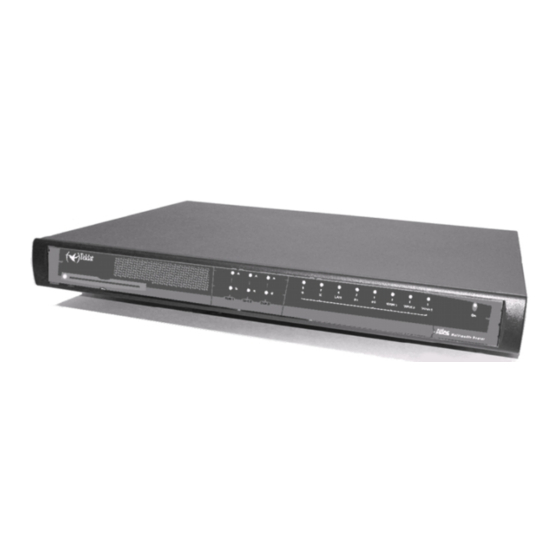
On the front panel, you can see the LEDs which display the status of the various interfaces and devices that the Atlas 250 router has. Located on the rear panel is the power point, the AUX console connection (in DB-9 format) for local configur- ation and monitoring and the micro-switches. -
Page 13: Description Of The Microswitches
3.2 Description of the microswitches In the interior of the Atlas 250 routers, you will find a group of SW2 micro-switches. These are identified by the num- bers ‘1’ to ‘8’ as shown in the below figure. These activate test functions, software loading functions etc. All these mi- cro-switches are in the OFF position by default. -
Page 14: Procedure To Ignore The Configuration
• Turn the device on with the ON/OFF switch. When the device is switched on, a message similar to the one shown below will appear on the configuration console: ************************************************** ******************* Router Teldat **************** ************************************************** BOOT CODE VERSION: 01.02 Dec 28 2004 12:56:28... - Page 15 As you can see, the text “Empty configuration used” appears in the box. On reaching this point, you can set micro- switch ‘5’ in the OFF position (it is not necessary to turn off the device). This way, the saved configuration will run next time you restart the device. Atlas 250...
-
Page 16: Appendix A Technical Information
• In order to view the content of the Smart Card, or the free space, use the ‘FILE LIST’ command from the configura- tion menu (please see manual “Dm704-I Configuration and Monitoring”). Given that the Smart Card is a slow device, it may take a few seconds to respond. Atlas 250... - Page 17 864 Jan 16 1999 ROUTER2.CFZ -rwxrwxrwx 1 ftp 3551 Jan 16 1999 STARTUP.CFZ -rwxrwxrwx 1 ftp 543 Jan 16 1999 ROUTER.CFZ 226 List transfer completed, data connection is closed. 591 bytes received in 18,25 seconds (0,03 Kbytes/sec) ftp> bye Atlas 250...
-
Page 18: Write
• FLASH. The Flash configuration is read. If the file cannot be found the device will boot with the default configura- tion. On saving the configuration through the ‘SAVE’ command, the behavior, depending on the active media is as follows: Atlas 250... -
Page 19: Format
As with any logical support, the Smart Card must be formatted before it can be used. The Smart Card is already formatted on leaving the factory. However, should it be necessary, the Atlas 250 has the means to do this. -
Page 20: Updating The Software And The Configurations
This is handled as a standard disk unit. The executable codes have a .bin extension and can by updated via FTP us- ing the Atlas 250 router FTP server, and by XModem through the device local console. The configurations have a .cfg extension and can only be read and written via FTP. If you wish to make copies of your configurations, simply obtain the .cfg router file possessed by the router. -
Page 21: Updating Using Ftp
Teldat S.A. A.3.1 Updating using FTP The Teldat devices have an internal FTP server that is capable of distinguishing if the loading file is from BIOS, an application or comes from another source. Therefore, the server operation is completely transparent. -
Page 22: Updating Via Xmodem
(not all of them are operative in this server). “help” <command_name> provides help on the indicated command. For further information, please consult the Teldat Router manual related to FTP, reference “Dm724-I FTP Protocol” . You can, at any point, view the status of the buffer through the “quote site statbuffer” command. If you wish to de- lete it, use the “quote site clearbuffer”... - Page 23 3. 19200 6. 115200 Press 0 to abort load... Set baud rate to 38400 and send the file with Xmodem with chk protocol. When the transfer finish, reset baud rate to 9600. Example of changing the transfer speed Atlas 250...
-
Page 24: Connecting The Connectors
Technical Information Teldat S.A. Code downloading via XModem through Windows Hyperterminal Fig. 16: A.4 Connecting the connectors A.4.1 Twisted pair connections (RJ45) RJ45 LAN RJ45 PIN Ethernet Tx+(input) Tx-(input) Rx+(output) Rx-(output) Atlas 250... -
Page 25: Isdn Connector
PC asynchronous port or terminal. DB9 PIN Signal Joined Pins 1-4-6 Joined Pins A.4.4 WAN Connector Note Cables used for multi-purpose Teldat drivers must not be used in these connections. You must use end-to-end pin-to-pin connector cables. Atlas 250... -
Page 26: Technical Specifications
Nº PORTS SPEED 10 Mbps (10BaseT)/ 100 Mbps (100BaseT) CONNECTOR RJ45 female WAN Interfaces PROTOCOLS FRAME RELAY, X.25, PPP, SDLC, X.28, SCADA INTERFACES Insertable Drivers V.24 / V.35 / X.21 DTE/ DCE and RS-485 2-4 Wire Nº PORTS Atlas 250... -
Page 27: Installing Pmc Cards
A.6 Installing PMC Cards The Atlas 250 features and interfaces can be amplified by inserting PMC boards (PCI mezzanine card). The Atlas 250 will support up to 3 cards simultaneously. In order to correctly insert the card, please follow the steps given be- low. - Page 28 (4) Find the place where the PMC board needs to be located, depending on the availability of the free slots and the mechanical characteristics of the PMC board. The following figure shows the Atlas 250 baseboard as seen from the device front panel. The various slots are labeled as SLOT1, SLOT2 and SLOT3.
- Page 29 (8) Place the PMC card in the slot so that it firstly adjusts to the space on the device rear panel and subsequently to the two PMC connections. This operation must be carried out carefully, without forcing any piece or part of the device. Check that the board is clearly settled over the PMC connectors. Atlas 250...
- Page 30 If the problem persists, please contact your usual supplier. (12) Connect a terminal to the console and check that the device detects the PMC board. This information is dis- played on booting as shown in the following figure. Atlas 250...
- Page 31 Technical Information Teldat S.A. (13) Finally, in order to use and configure the board, you need to boot the device with a default configuration. Atlas 250...
-
Page 32: Appendix B Safety Information
B.1 Recycling and the Environment Please do not, under any circumstances, throw away any Atlas 250 with normal domestic waste. Ask your local town hall for information on how to correctly dispose of them in order to protect the environment against e-waste. Always respect the current laws regarding waste material.
Need help?
Do you have a question about the Atlas 250 and is the answer not in the manual?
Questions and answers