
Subscribe to Our Youtube Channel
Related Manuals for Teldat Atlas-i70


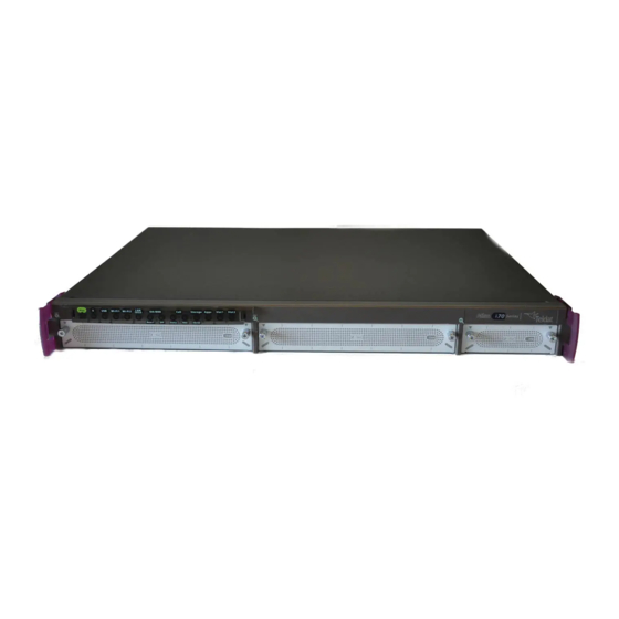
Summary of Contents for Teldat Atlas-i70
- Page 1 Manual Teldat S.A. Teldat Router Atlas-i70 Installation Manual Copyright© Teldat Dm667-I Version 1.1 3/2017 Teldat S.A. Teldat Router Atlas-i70...
- Page 2 This publication is subject to change. Teldat S.A. offers no warranty whatsoever for information contained in this manual. Teldat S.A. is not liable for any direct, indirect, collateral, consequential or any other damage connected to the deliv- ery, supply or use of this manual.
-
Page 3: Table Of Contents
WAN Connection ........Teldat Router Atlas-i70... - Page 4 Dimensions and weight ....... . A.5.9 Environmental Specifications ......Teldat Router Atlas-i70...
-
Page 5: I Related Documents
Related Documents Teldat S.A. I Related Documents Teldat Dm748-I Software Updating Teldat Router Atlas-i70... -
Page 6: Chapter 1 About This Guide
1 About This Guide Teldat S.A. Chapter 1 About This Guide This installation guide for the Teldat Atlas-i70 router contains information on how to correctly install this device in a working environment. 1.1 Supported Devices The information provided in this installation guide only applies to the Teldat Atlas-i70 router. -
Page 7: Chapter 2 Teldat Atlas-I70
2.1.2 Hardware Monitoring The LEDs on the front panel are used to monitor the hardware in the Teldat Atlas-i70 router. These LEDs provide visual information on the state of the device and reference the condition of the hardware components, indicating whether there is connectivity, data flow, etc. -
Page 8: Chapter 3 Components And Power Supply
3 Components and Power Supply Teldat S.A. Chapter 3 Components and Power Supply The following chapter provides detailed information on the chassis of the Teldat Atlas-i70 router and its compon- ents. This information includes: • Components. • Information on assembly. - Page 9 Amber -> Auto-test. Green -> Interface up (blinking, in some cards, when there is con- nection data activity). Slot 2 Expansion Slot 2 Information Off -> There is no card in the expansion slot. Red -> Interface down. Teldat Router Atlas-i70...
-
Page 10: Rear Panel
Green -> Link detected. Blinking: con- nection data activity. 3.1.2 Rear Panel The following figure shows the rear panel. Here you will find the majority of the Teldat Atlas-i70 router connectors. Rear panel Fig. 3: The following table provides information on each connector, as well as a description:... -
Page 11: Expansion Slots
On/Off switch. 3.2 Expansion Slots The Teldat Atlas-i70 router has two expansion slots. This allows you to increase the features and interfaces by in- serting different cards or boards. These slots are located on the router's front panel, as shown in the following figure: Expansion slots Fig. -
Page 12: Installation In A Rack
3.3 Installation in a rack The Teldat Atlas-i70 device can be installed in a 19” rack. The necessary strips and screws are not provided by de- fault and have to be acquired separately. -
Page 13: Standalone
Fig. 10: 3.3.1 Standalone Teldat Atlas-i70 devices can be placed as standalones on a flat, stable surface. The adhesive rubber feet must be stuck to the underside panel to prevent the router from sliding. Make sure there is enough space around the router (for ventilation purposes) and check that the power cord and data cables can reach it. -
Page 14: Plug-In Modules
The Teldat Atlas-i70 router is powered through an internal AC/DC source. The Teldat Atlas-i70 may also incorporate a card to inject PoE through the 4 ports of the 8-port Switch. In this case, an external adapter is needed to provide power to PoE module. -
Page 15: Poe Source
• Disconnect the data cables. 3.5.2 PoE Source The Teldat Atlas-i70 can be powered through an Ethernet cable that complies with the PoE 802.3af standard (15.4 W per port). This feature needs an external adapter and internal card to work. - Page 16 ICache:ON DCache:ON Write-Back L2Cache:ON Mem Info: DRAM size: 1024 Megabytes BANK 0: 1024 Megabytes FLASH: 32256 KB. EEPROM: 16384 Bytes. Devices: SWITCH(8) 10/100/1000 USB 2 USB 1 NVRAM 128 KB SECURITY ENGINE(0x0a120500) POE CARD 0 GIGABIT ETHERNET 1 Teldat Router Atlas-i70...
-
Page 17: Rst Button
Once the MiniPoE card has been installed, we can connect the PoE source to the device: Connecting the PoE source to the device through external PoE adaptor connector Fig. 16: 3.6 RST Button The different RST button features are described below. RST button Fig. 17: Teldat Router Atlas-i70... -
Page 18: Rebooting The Device
3.7.2 WAN Connection The Teldat Atlas-i70 has one Ethernet interface for WAN connection. This port has two connectors - SFP for optical link and RJ45 for 10/100/1000 Base-T link - but they cannot work simultaneously. This interface is totally independ- ent from the switch and is handled as just one more interface. -
Page 19: Connecting A 3G Usb Device (Usb Connector)
3.7.3 Connecting a 3G USB device (USB connector) The Teldat Atlas-i70 router has a USB HOST 2.0 Type A connector interface. It allows 3G USB modems to be con- nected. The interface can be activated by purchasing the corresponding software license. - Page 20 Then fix the hard disk using the appropriate 4 screws, taking care not to damage it during the tightening process (red arrows). Placing the hard disk Fig. 24: (6) Finally, insert the tray into the device once again using the slot guides. Teldat Router Atlas-i70...
-
Page 21: Procedure To Install A Flash Memory Expansion Sd
(8) Connect the equipment as indicated in section 3.5.1.1 "Connecting". Connect the terminal to the console and check that the device detects the hard disk. 3.8.2 Procedure to install a flash memory expansion SD To install an SD card, insert it into the SD tray as shown in the following figure: Teldat Router Atlas-i70... - Page 22 3 Components and Power Supply Teldat S.A. Inserting SD card Fig. 27: Teldat Router Atlas-i70...
-
Page 23: Chapter 4 Compliance
Teldat S.A. Chapter 4 Compliance 4.1 Manufacturer Information Teldat Brand Manufacturer Teldat S. A. Country Spain Postal Address Isaac Newton, 10 Parque Tecnológico de Madrid, 28760 Tres Cantos, Madrid, Spain International Phone +34 91 807 65 65 Teldat Router Atlas-i70... -
Page 24: Safety Warnings
4 Compliance Teldat S.A. 4.2 Safety Warnings Connecting Discon- necting Teldat Router Atlas-i70... -
Page 25: Weee Information
Directive 2009/125/EC (ErP) Directive 2011/65/EU (RoHS) of the European Parliament and of the Council. Spanish (ES) Español Por la presente, Teldat S.A. declara que el tipo de equipo radioeléctrico Teldat At- las-i70 es conforme con: Directiva 2014/30/UE (EMC) Directiva 2014/35/UE (LVD) -
Page 26: Laser Product
• IEC/EN 60950-1, IEC/EN 60825-1 and IEC/EN 60825-2 European standard • FCC 21 CFR Chapter 1, Subchapter J (in accordance with FDA and CDRH re- quirements) • UL and/or CSA registered component for North America • 47 CFR Part 15, Class A Teldat Router Atlas-i70... -
Page 27: Appendix A Technical Information
A.3 Connecting to the device A.3.1 Connecting using the local console (Aux connector) The Teldat Atlas-i70 router has a RJ45 female connector on the front panel ( Aux.), which provides access to the device's local console. Aux Connector Fig. 30: To configure this, connect the Aux. -
Page 28: Connectors
RJ45 female-DB9 female adapter (also provided). Connecting for Configuration Fig. 31: A.4 Connectors A.4.1 LAN Connector (Switch) RJ45 LAN RJ45 PIN FE Signals GE Signals BI-DA+ [PoE+] BI-DA+ BI-DA- [PoE+] BI-DA- BI-DB+ [PoE-] BI-DB+ BI-DC+ BI-DC- BI-DB- [PoE-] BI-DB- BI-DD+ BI-DD- Teldat Router Atlas-i70... -
Page 29: Wan Base-T Connector
RJ45 WAN RJ45 PIN FE Signals GE Signals BI-DA+ BI-DA+ BI-DA- BI-DA- BI-DB+ BI-DB+ BI-DC+ BI-DC- BI-DB- BI-DB- BI-DD+ BI-DD- A.4.3 WAN SFP Connector Standard SFP connector A.4.4 USB Connector USB Type A DATA- DATA+ Shell Shield Teldat Router Atlas-i70... -
Page 30: Configuration Connector
FLASH Memory (32 Mbytes). A.5.2 LAN Interface PROTOCOLS Ethernet (802.3). PORTS 8-port switch managed with MDI/MDX auto-detection. SPEED 10/100/1000 Mbps (Base-T). CONNECTOR RJ45 female. A.5.3 WAN Base-T Interface STANDARDS Ethernet (802.3). SPEED 10/100/1000 Mbps (Base-T). CONNECTOR RJ45 female. Teldat Router Atlas-i70... -
Page 31: Wan Sfp Interface
CONNECTOR Standard SFP connector. A.5.5 USB Interface 3G USB MODEMS Please visit the Teldat website http://www.teldat.com for a list of supported 3G USB modems. SPEED The interface complies with the USB 2.0 (480 Mbps) standard; the end speed de- pends on the 3G USB modem used. -
Page 32: Environmental Specifications
Technical Information Teldat S.A. A.5.9 Environmental Specifications TEMPERATURE OPERATING NORMALLY: 0 ºC to 40 ºC. STORED: -25 ºC to 70 ºC. RELATIVE HUMIDITY On: 5 % to 90 %. Teldat Router Atlas-i70...
Need help?
Do you have a question about the Atlas-i70 and is the answer not in the manual?
Questions and answers