Welch Allyn Connex Service Manual
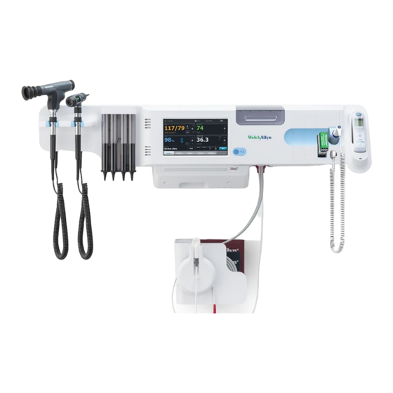
Integrated wall system
Hide thumbs
Also See for Connex:
- Service manual (221 pages) ,
- Directions for use manual (96 pages) ,
- Startup manual (23 pages)
Table of Contents
Advertisement
Advertisement
Table of Contents

Subscribe to Our Youtube Channel
Related Manuals for Welch Allyn Connex


Summary of Contents for Welch Allyn Connex
- Page 1 ® Welch Allyn Connex Integrated Wall System Service manual Software version 2.3X...
- Page 2 © 2017 Welch Allyn. All rights are reserved. To support the intended use of the product described in this publication, the purchaser of the product is permitted to copy this publication, for internal distribution only, from the media provided by Welch Allyn. No other use, reproduction, or distribution of this publication, or any part of it, is permitted without written permission from Welch Allyn.
-
Page 3: Table Of Contents
Overview ....................9 Purpose and scope ....................9 Technical support services ................. 10 Recommended service intervals ................ 14 The Welch Allyn Service Tool ................15 Battery performance ..................16 Controls, indicators, and connectors ........... 19 Service menu ..................23 Access the Service screens ................23 General tab ...................... - Page 4 Service and repair training ................117 Appendices ..................119 Decontamination and cleaning requirements ..........119 Configuration options ..................120 Factory defaults ....................122 Disassembly and repair reference ..............131 Connex Integrated Wall System interconnect diagram ........139 Service record ....................140...
-
Page 5: Symbols
Follow the operating instructions/directions for use (DFU) — mandatory action. A copy of the DFU is available on this website. A printed copy of the DFU can be ordered from Welch Allyn for delivery within 7 days. Power symbols Power on/Display power-saving... - Page 6 ® Symbols Welch Allyn Connex Integrated Wall System (on the device, green indicator) Battery charge level Alternating Current power present, battery fully charged (on the device, amber indicator) Battery cover Alternating Current power present, battery is charging Alternating Current (AC)
- Page 7 Service manual Symbols 3 Nonionizing electromagnetic Recycle the product separate from radiation other disposables Restrictions for use of wireless Call for maintenance device in Europe. European Community's Class 2 radio equipment. Defibrillation-proof Type BF applied Do not expose to open flame parts Atmospheric pressure limitation Not for injection...
- Page 8 ® Symbols Welch Allyn Connex Integrated Wall System...
-
Page 9: Safety
Safety All users of the system must read and understand all safety information presented in this manual before using or repairing the system. United States federal law restricts this device to sale, distribution, or use by or on the order of a licensed medical practitioner. Warnings and cautions WARNING Safety risk. -
Page 10: General Safety Considerations
• To ensure patient safety, use only accessories recommended or supplied by Welch Allyn. (See the accessories list in the Welch Allyn Connex Integrated Wall System Directions for use on the user documentation CD or http://www.welchallyn.com. Always use accessories according to your facility’s standards and according to the manufacturer’s recommendations and instructions. - Page 11 Service manual Safety 7 • Remove static-sensitive components and assemblies from their static-shielding bags only at static-safe workstations—a properly grounded table and grounded floor mat— and only when you are wearing a grounded wrist strap (with a resistor of at least 1 megohm in series) or other grounding device.
- Page 12 ® 8 Safety Welch Allyn Connex Integrated Wall System...
-
Page 13: Overview
Purpose and scope This manual is a reference for periodic preventive maintenance and corrective service procedures for the Welch Allyn Connex Integrated Wall System, firmware version 2.3X. It is intended for use only by trained and qualified service personnel. Corrective service is supported to the level of field-replaceable units. These include circuit-board assemblies and some subassemblies, case parts, and other parts. -
Page 14: Technical Support Services
Partners in Care service agreements While product warranties provide basic assurance of Welch Allyn hardware quality, they may not include the full range of services and support you need. Welch Allyn offers premium service and support through our Partners in Care program. Whether you service your own devices and require a minimum of support or rely on us to service your device, Welch Allyn provides a program that will meet your needs. - Page 15 Qualified service personnel or a Welch Allyn Service Center should repair products out of warranty. If you are advised to return a product to Welch Allyn for repair or routine maintenance, schedule the repair with the service center nearest you.
- Page 16 12 Overview Welch Allyn Connex Integrated Wall System Returning products When returning a product to Welch Allyn for service, ensure that you have the following information: • Product name, model number, and serial number. This information may be found on the product and serial number labels on the bottom of the device.
- Page 17 Remember that the device and any batteries must be packed and shipped separately. e. Write the Welch Allyn RMA number with the Welch Allyn address on the outside of the shipping carton. WARNING Safety risk. Do not ship any battery that has...
-
Page 18: Recommended Service Intervals
To confirm that the device is functioning within the design specifications, perform periodic service as indicated in the following table. Customers who have the Standard unlicensed edition of the Welch Allyn Service Tool can perform the basic functional verification and calibration procedures referenced in the table by following the instructions in this manual. -
Page 19: The Welch Allyn Service Tool
Welch Allyn technical training course or complete online training for the device. Clinicians and technical service personnel can use the service tool to manage and maintain supported Welch Allyn products. You can use the service tool to do the following: •... -
Page 20: Battery Performance
Integrated Wall System • Recover devices. In the rare case where a device can no longer boot because of corrupted firmware, the service tool can connect the device to Welch Allyn Technical Support to reinstall the firmware. • Extensible. The service tool software accepts new plug-ins to support future Welch Allyn products. - Page 21 Service manual Overview 17 ○ For storage less than 30 days: Maintain temperature between –4 °F and 122 °F (–20 °C and 50 °C). ○ For storage between 30 days and 90 days: Maintain temperature between –4 °F and 104 °F (–20 °C and 40 °C). ○...
- Page 22 ® 18 Overview Welch Allyn Connex Integrated Wall System...
-
Page 23: Controls, Indicators, And Connectors
Description Front view Physical assessment instruments - Handles Handles accept any 3.5V Welch Allyn instrument head. and handle cradles Handle cradles support using one handle at a time. A handle turns on automatically when you remove it from a cradle and turns off when you return it. - Page 24 ® 20 Controls, indicators, and connectors Welch Allyn Connex Integrated Wall System No. Feature Description Braun ThermoScan® PRO thermometer and Support temperature measurements from the ear. Dock charges dock the thermometer battery. SureTemp® Plus thermometer connector Secures the probe connection to the wall system.
- Page 25 Service manual Controls, indicators, and connectors 21 No. Feature Description USB connectors Provides access to host USB connections for optional accessories. USB cable retainer Reduces strain on USB cables and connectors; helps prevent cables from disconnecting. Back view Recess for mounting bracket Secures the monitor when mounted on the wall.
- Page 26 ® 22 Controls, indicators, and connectors Welch Allyn Connex Integrated Wall System No. Feature Description Mounting materials Wall mounting rail bracket and hardware Secures the wall system to the wall. Accessory bin mounting bracket and Secure accessory bin to the wall and provide routing and strain hardware relief for power cord.
-
Page 27: Service Menu
Service menu Access the Service screens Note You cannot access the Service screens if sensors or physiological alarms are active or if vital sign measurements are displayed. 1. From the Home tab, touch the Settings tab. 2. Touch the Advanced tab. 3. - Page 28 ® 24 Service menu Welch Allyn Connex Integrated Wall System If you selected All settings, the device reboots. Save the device configuration or custom data to a drive You can save the device configuration or custom data (custom modifiers and custom scoring) to a USB flash drive.
- Page 29 Service manual Service menu 25 2. Go to the Service screens as described in “Access the Service screens.” 3. Touch the General tab. 4. Select Configure from USB. A confirmation dialog appears. 5. Select Device configuration and/or Custom data XML. A confirmation dialog appears to confirm overwriting the existing configuration.
-
Page 30: Self-Tests Tab
® 26 Service menu Welch Allyn Connex Integrated Wall System Send device information to PartnerConnect The device sends technical information, such as log files, to PartnerConnect periodically. You can also manually send this information at any time by following this procedure. -
Page 31: Device Tab
Service manual Service menu 27 5. Touch OK. Copies of both log files are saved to the drive. Device tab View device and module information 1. Go to the Service screens as described in “Access the Service screens.” 2. Touch the Device tab. Device and module information appears for you to view. - Page 32 ® 28 Service menu Welch Allyn Connex Integrated Wall System...
-
Page 33: Power-Up Sequence
2. Insert a fully charged battery into the system. 3. Upon each power up, confirm the following: a. The light bar flashes amber. b. The Welch Allyn startup screen appears. c. A beep sounds, followed by one chime. Note If no chimes sound, replace the speaker as specified in “Remove the speaker.”... - Page 34 ® Power-up sequence Welch Allyn Connex Integrated Wall System...
-
Page 35: Troubleshooting
AC power and call Welch Allyn Technical Support immediately. CAUTION Replace parts, components, or accessories only with parts supplied or approved by Welch Allyn. The use of any other parts can lead to inferior performance and will void the product warranty. Symptoms and solutions... - Page 36 ® 32 Troubleshooting Welch Allyn Connex Integrated Wall System Symptom Possible cause Suggested action An internal connection is faulty Check the power-flex cable connection at J6 on the main board. Check the AC power harness connections from the IEC connector to the power supply.
- Page 37 Service manual Troubleshooting 33 Mechanical Symptom Possible cause Suggested action Cracks in housing Non-approved cleaning agents Replace plastic housing as necessary. Use only approved cleaning agents. Display Symptom Possible cause Suggested action The touchscreen does not respond Software error Reboot the device. Press and hold the power button until the device shuts down.
-
Page 38: User Interface
® 34 Troubleshooting Welch Allyn Connex Integrated Wall System Symptom Possible cause Suggested action The device powered down after a period of Turn on the device by pressing inactivity Power button. In Advanced Settings, touch the General tab and then touch... - Page 39 Service manual Troubleshooting 35 Communication Symptom Possible cause Suggested action Cannot communicate through the The battery charge is low Connect the device to AC power USB client connection and allow the battery to fully charge. The communications board does not receive Check the voltage from J49 on power the main board for +5.0, ±0.5V...
- Page 40 ® 36 Troubleshooting Welch Allyn Connex Integrated Wall System Symptom Possible cause Suggested action The network Ethernet switches are not set to the Set the switches to 10 Mbps full correct speed to work with the device duplex. The cable run to the switch is too long Use a shorter patch cable.
- Page 41 Check the error logs for NIBP errors. See the service tool help files for details on specific errors and suggested actions. Check with Welch Allyn for software updates. If no NIBP error is logged, the main board might Replace the main board if be defective necessary.
- Page 42 Check the error logs for SpO2 errors. See the service tool help files for details on specific errors and suggested actions. Check with Welch Allyn for software updates. If no SpO2 error is logged, the main board might Replace the main board if be defective necessary.
- Page 43 Service manual Troubleshooting 39 Symptom Possible cause Suggested action The weight scale is not licensed Purchase a license and install the license using the service tool. The weight scale is not connected Check cables and connections. Use the service tool to test connectivity.
- Page 44 ® 40 Troubleshooting Welch Allyn Connex Integrated Wall System For additional troubleshooting tips for the thermometer, see the Note manufacturer’s product documentation. Braun ThermoScan PRO 6000 thermometer Symptom Possible cause Suggested action Braun measurements are inaccurate Probe lens is displaced Examine lens for displacement.
- Page 45 C/F button or return to the dock while holding the C/F button. Retry upgrade. *Host device Braun 6000 settings override configuration settings from Welch Allyn Service Tool. Note For additional troubleshooting tips for the thermometer, see the manufacturer’s product documentation.
- Page 46 For Honeywell model 4600g barcode readers, verify that the PID is set to 020A. The barcode scanner did not enumerate properly Power cycle the Connex device. The patient ID or clinician ID do not The barcode scanner is not programmed to properly...
- Page 47 Note The GS 777 Wall Transformer will accommodate instrument heads of the Welch Allyn approved Halogen and LED type bulbs without any manual adjustment. For information about instrument heads, follow the instructions provided in their directions for use.
-
Page 48: Technical Alarm Messages
® 44 Troubleshooting Welch Allyn Connex Integrated Wall System Symptom Possible cause Suggested action #000000009 An audio system error #000000010 An Ethernet system error #000000011 The touchscreen controller failed #000000012 Five or more SMBUS errors over a 1-minute period occurred... - Page 49 Check the error logs for NIBP service. errors. See the service tool help files for details on specific errors and suggested actions. Check with Welch Allyn for software updates. The ambient temperature is out of range Use the monitor in the specified temperature range.
- Page 50 Check the error logs for SpO2 errors. See the service tool help files for details on specific errors and suggested actions. Check with Welch Allyn for software updates. Attach SpO2 sensor to monitor. The sensor was not detected Check the sensor connection.
- Page 51 Service manual Troubleshooting 47 Message Possible cause Suggested action Reattach the SpO2 sensor to the patient's finger. Low SpO2 signal quality. Check Poor sensor placement on the patient. Remove the sensor from the sensor. patient and reapply. Low SpHb signal quality. Check sensor.
- Page 52 ® 48 Troubleshooting Welch Allyn Connex Integrated Wall System Message Possible cause Suggested action have installed the CAL-KEY assembly, replace the module. Insert correct color-coded probe The probe well is missing Insert a temperature probe well. well. The SureTemp temperature module is faulty...
- Page 53 Service manual Troubleshooting 49 Temperature messages (Braun ThermoScan PRO) Message Possible cause Suggested action Alarm Unable to detect temperature. Retry measurement. Measurement was not taken Retry measurement. Measurement recalled from memory Loose or broken USB cable Check USB connection and cable. Replace as necessary.
- Page 54 See the service tool help files for details on specific errors and suggested actions. Check with Welch Allyn for software updates. The USB cable is disconnected Check the USB cable. The battery is depleted or missing Replace the batteries.
- Page 55 Service manual Troubleshooting 51 Message Possible cause Suggested action The communications board malfunctioned Replace the communications board. Radio messages Message Possible cause Suggested action Alarm Radio not functional. Call for A hardware failure occurred Replace the radio. service. The radio has the wrong software Update the radio software.
- Page 56 A device requiring a license has been connected Obtain an authorization code use. to the USB connection from Welch Allyn to activate the license. Unable to save configuration to There was a problem writing the configuration Use a Welch Allyn approved USB.
-
Page 57: System Messages
The date or time is not set Set the date and time. The date or time is not set properly Reset the date or time. Incompatible Welch Allyn device. A known USB device enumerates, but fails The device may be faulty. Test a known good device. - Page 58 ® 54 Troubleshooting Welch Allyn Connex Integrated Wall System Message Possible cause Suggested action Information Device is operating in battery The AC power cord has been disconnected Touch the alarm icon to dismiss mode. or plug the monitor to AC power.
- Page 59 Service manual Troubleshooting 55 Message Possible cause Suggested action management tab in Advanced settings. Patient ID required to send data. The configuration requires a patient ID to send Add a patient ID. data Patient list is full. Delete some The maximum number of patients was exceeded Delete a patient from the list to patients to add more.
- Page 60 ® 56 Troubleshooting Welch Allyn Connex Integrated Wall System...
-
Page 61: Disassembly And Repair
For more information about these tests and the service tool, see “Functional verification and calibration.” If you do not have the service tool, contact Welch Allyn Technical Support. WARNING Electrical shock hazard. Disconnect AC power before opening the system. Disconnect and remove the battery before proceeding with disassembly. -
Page 62: Required Tools And Equipment
® 58 Disassembly and repair Welch Allyn Connex Integrated Wall System CAUTION When the system case is opened, regard all parts as extremely fragile. Execute all procedure steps with care and precision. CAUTION Observe screw torque specifications, especially with screws that secure directly into plastic standoffs. - Page 63 Service manual Disassembly and repair 59 Option 1. After the device is powered up, a brief press of the power button opens an onscreen dialog with the following options: • Power down. Device behavior varies based on the active profile, whether or not patient trend data is stored, and whether or not patient context is established.
-
Page 64: Module Replacement - Bottom Housing
® 60 Disassembly and repair Welch Allyn Connex Integrated Wall System – If you opted to remove patient data from the device, monitoring and patient assignment end, and trend data on the device is deleted. • Cancel. This button dismisses the dialog and returns you to the previous screen. -
Page 65: Module Replacement - Main Housing
Service manual Disassembly and repair 61 7. Disconnect the USB cable from the rear of the module. Reassembly notes • When aligning the module with the housing, the USB connection is on the left. • The NIBP module must always be in the front-most slot. Module replacement —... - Page 66 ® 62 Disassembly and repair Welch Allyn Connex Integrated Wall System 3. For systems with the Braun thermometer option, disconnect the USB cable from the rear of the Braun housing. 4. Locate and remove the module retaining plate by removing the four #2 Phillips screws.
-
Page 67: Remove The System From The Wall And Remove The Battery
Service manual Disassembly and repair 63 Reassembly notes • When aligning the module with the housing, the USB connection is on the bottom. • The temperature module must always take up the last two spots closest to the end. • The blank cover's beveled edge must be on the right when facing the device for proper alignment. -
Page 68: Remove The Handle Module Assembly
® 64 Disassembly and repair Welch Allyn Connex Integrated Wall System 6. Remove the AC power cord. 7. Remove the comms connection cover. Loosen the two captive screws, using a number 2 Phillips screwdriver, until the cover is free from the housing. -
Page 69: Remove The Handles
Service manual Disassembly and repair 65 4. Remove the four large Phillips screws while supporting the end of the handle module assembly. 5. Lift the handle module assembly up and away from the main assembly while guiding the USB cable through the slotted opening. Remove the handles •... -
Page 70: Remove The 767 Controller Pcba
® 66 Disassembly and repair Welch Allyn Connex Integrated Wall System Reassembly note When reconnecting the handle connection wires to the handle PCBA, the connecting wires must be facing up and away from the PCBA. Remove the 767 controller PCBA •... - Page 71 Service manual Disassembly and repair 67 2. Push in the snap tabs and remove the cradle assembly by pushing outward. Reassembly notes • For ease of assembly, connect the IR wire assemblies to the optical sensors before attaching the handle cradle to the handle assembly housing. •...
-
Page 72: Open The Chassis
® 68 Disassembly and repair Welch Allyn Connex Integrated Wall System Open the chassis • Remove the system from the wall and remove the battery as described. • Remove the handle module assembly from the main assembly as described. •... -
Page 73: Remove The Power Supply
Service manual Disassembly and repair 69 Number Item Small 4-pin connector Mini USB cable USB cable Ethernet cable 4. Disconnect the power supply cable from the power supply. 5. Separate the chassis from the front housing. Remove the power supply •... -
Page 74: Remove The Ground Lug, Ac Power Harness Assembly, And Iec Connector
® 70 Disassembly and repair Welch Allyn Connex Integrated Wall System 3. Remove the power supply. Reassembly notes • When reinstalling the power supply, orient the board so that the end of the board with the AC to power supply (J1) connection is closest to the IEC connector. -
Page 75: Remove The Communications Board
Service manual Disassembly and repair 71 Note You must now replace the AC power harness. It cannot be reused. b. Push in on the three plastic release tabs to release the IEC connector. Remove the communications board • Open the chassis as described. 1. -
Page 76: Remove The Radio Board And Antenna
® 72 Disassembly and repair Welch Allyn Connex Integrated Wall System 6. If replacing the communications board, remove the radio board as described in "Remove the radio board and antenna." Remove the radio board and antenna CAUTION Do not remove the radio antenna from the chassis unless you are replacing the radio and antenna or the chassis. -
Page 77: Remove The Light Bar
Service manual Disassembly and repair 73 a. Remove the Pro Gaff tape securing the antenna cable to the housing. b. Carefully disconnect the antenna cable by lifting up on the wire neck just before the connection point. c. Use a soft tool such as a spudger to separate the adhesive from the inside of the chassis of the antenna plate. -
Page 78: Remove The Fan
® 74 Disassembly and repair Welch Allyn Connex Integrated Wall System 2. Remove the light bar and cover. 3. Remove the light bar from the light-bar cover. 4. Disconnect the light-bar harness from the light-bar board. 5. Remove the light-bar board from the light bar by sliding the board out from the connector end. -
Page 79: Remove The Power Panel
Service manual Disassembly and repair 75 2. Press the flanges on the sides of the fan harness connector and separate the fan connector from the power panel. 3. Slide the fan up and remove. Remove the power panel • Open the chassis as described. •... -
Page 80: Remove The Speaker
® 76 Disassembly and repair Welch Allyn Connex Integrated Wall System 2. Disconnect the speaker connector wire. 3. Remove the two torx screws that attach the power panel to the front housing and slide the power panel out of the housing. -
Page 81: Remove The Battery Board
Service manual Disassembly and repair 77 Remove the battery board Before you begin, remove the following as described in the manual: • Power Panel 1. Remove the battery compartment from the power panel by pushing in on the four plastic tabs. 2. -
Page 82: Remove The Main Board
® 78 Disassembly and repair Welch Allyn Connex Integrated Wall System 2. Disconnect the connectors at J29 and J30 to disconnect the power harness. 3. Disconnect the connectors at J34, J12, J49, J46, and J45 to disconnect the main harness. - Page 83 Service manual Disassembly and repair 79 1. Disconnect the following on the main board: a. The power button flex cable at J6. b. The LCD harness at J19. c. The LCD flex cable at J48. 2. Remove the Ethernet cable: a.
- Page 84 Enter the device’s serial number. This can be found on the bottom of the device. ○ Enter the main board (host controller) serial number. ○ Select the device model number from the Connex Integrated Wall System dropdown menu. ○ Restore any previously licensed features by entering the authorization code in the service tool.
-
Page 85: Remove The Lcd
Update the host controller software to the current version or version in use at your facility. If the required version of the host software is not available after connecting the device to the service tool, contact Welch Allyn Technical Support. Remove the LCD Before you begin, remove the main board as described. - Page 86 ® 82 Disassembly and repair Welch Allyn Connex Integrated Wall System • Place the LCD frame over the LCD. Verify that the LCD frame does not cover the LCD flex cable. • Replace the Pro gaff tape in the frame opening under the display harness as shown.
-
Page 87: Remove The Module Well
Service manual Disassembly and repair 83 • When adding the ferrite beads, align the beads with the marks on the LCD frame. • Add Pro Gaff tape to secure the harness to the LCD frame where the harness passes through. Remove the module well •... -
Page 88: Remove The Front Housing
® 84 Disassembly and repair Welch Allyn Connex Integrated Wall System Module USB connectors USB slot Material number Connection 715891 MCE to modules—Braun if installed 715891 MCE to modules 715891 MCE to modules 715891 MCE to modules 715891 MCE to modules... - Page 89 Service manual Disassembly and repair 85 3. Disconnect the power button cable from the main board at J6. 4. Disconnect and remove the Ethernet cable. 5. Remove the four large Phillips screws that mount the LCD to the housing. 6. Carefully lift the LCD and the attached main board from the housing. CAUTION Support the LCD as you lift the assembly from the housing.
-
Page 90: Replace The Power Button
® 86 Disassembly and repair Welch Allyn Connex Integrated Wall System Replace the power button • Open the chassis as described. • Remove the module well as described. 1. Disconnect the power button flex cable from the main board at J6. -
Page 91: Functional Verification And Calibration
These tests are for customers who have the Standard unlicensed edition of the Welch Allyn Service Tool. If you have the Gold licensed edition of the service tool, use the tool to perform a complete functional verification and calibration of the device in lieu of performing the basic tests. - Page 92 ® 88 Functional verification and calibration Welch Allyn Connex Integrated Wall System • To use the Standard unlicensed edition to test the NIBP module, follow the instructions in this service manual. • For instructions on using the Gold licensed edition, see the service tool help files.
- Page 93 Service manual Functional verification and calibration 89 Test Description NIBP Temp SpO2 SpHb Host Valve control Verifies control of the system valve Overpressure Verifies pump limits Probe detect Verifies the operation of the probe detect switch² Accuracy (Temp) Verifies the accuracy of the thermometer across range Functional check Verifies module operation with cal-...
-
Page 94: Basic Functional Verification Checks
Note Calibration is available only with the service tool, Gold licensed edition. The basic functional verification test using the Welch Allyn Service Tool Standard edition meets the minimum requirements for routine preventive maintenance. These tests verify basic functionality of the NIBP, SpO2, SpHb, and thermometry parameters. Welch Allyn recommends using the service tool, Gold licensed edition, to perform verification of the device when completing a repair. - Page 95 Full functional verification check and calibration tools The list of tools below is what is required to perform a full device functionality check and calibration. The tools are used in conjunction with the Welch Allyn service tool, Gold licensed edition, to perform a device calibration.
- Page 96 ® 92 Functional verification and calibration Welch Allyn Connex Integrated Wall System Material no. Description Component 4500-30 Blood pressure hose, 5 ft. NIBP 620216 Fitting "Y" 1/8 X 1/8 X 1/8 NIBP Create a blood pressure Y-tube The blood pressure Y-tube is a piece of custom test equipment that connects the device to the test setup.
- Page 97 Service manual Functional verification and calibration 93 Item Item Blood pressure Y-tube NIBP leak test (Standard unlicensed edition) The NIBP leak test is performed automatically using the service tool. The leak test pressurizes the system with a start pressure (P ) of 250 mmHg ±...
- Page 98 To ensure patient safety, Welch Allyn recommends that a qualified service technician perform a full functional verification and calibration on an annual basis.
- Page 99 Service manual Functional verification and calibration 95 12. Record the reading on the pressure meter and the service tool and compare the results. 13. Using the hand bulb, pressurize the NIBP system to 50 mmHg ± 5 mmHg and allow 10 seconds for the pressure to stabilize.
- Page 100 The tester takes approximately 20 minutes to heat to the lowest set point. To expedite testing, Welch Allyn recommends the following practices: • To eliminate waiting for the tester to heat to the next set point, use three testers, each set to one of three different set points.
- Page 101 Use this procedure in place of the verification and calibration test for the Note Braun PRO 4000 and Braun PRO 6000 in the Welch Allyn Service Tool version 1.0.2.0 and earlier. CAUTION Before the test, place thermometers and tester in the same room for approximately 30 minutes so that they adjust to the ambient temperature.
- Page 102 ® 98 Functional verification and calibration Welch Allyn Connex Integrated Wall System 1. Complete the following pre-check steps: a. Check the probe tip lens window with a magnifying glass for signs of displacement. Any gaps in the seam between bezel and the lens window indicate a displaced lens window.
- Page 103 Service manual Functional verification and calibration 99 Perform a Braun ThermoScan PRO 6000 functional verification test 1. Complete the following pre-check steps: a. Check the probe tip lens window with a magnifying glass for signs of displacement. Any gaps in the seam between bezel and the lens window indicate a displaced lens window.
- Page 104 ® 100 Functional verification and calibration Welch Allyn Connex Integrated Wall System 9. Remove the Braun PRO 6000 thermometer from the 9600 Plus Calibration Tester and compare the temperature displayed on the tester with the temperature on the thermometer’s display.
-
Page 105: Electrical Safety Testing
Medical Electrical Equipment - Recurrent Test and Test After Repair of Medical Electrical Equipment. Due to the variability of test equipment in the field, Welch Allyn does not include specific instructions to perform electrical safety tests. When performing electrical safety tests, refer to your test equipment manuals for detailed instruction. - Page 106 ® 102 Electrical safety testing Welch Allyn Connex Integrated Wall System Item Description Type Order no. The mating electrical connector, a right-angled socket made of nickel- POAG-WB6DIN 01.0404 plated brass with Multilam™ made of gold-plated, hard-drawn copper alloy. Insulator T-POAG6 15.5004-24...
-
Page 107: Options, Upgrades, And Licenses
The training is required to be eligible to receive the Welch Allyn Service Tool Gold licensed edition. The Gold licensed edition is required to verify that the device is functioning correctly after it has been serviced. -
Page 108: Available Options, Upgrades, And Licenses
® 104 Options, upgrades, and licenses Welch Allyn Connex Integrated Wall System Available options, upgrades, and licenses The following options, upgrades, and licenses can be added to each model’s base configuration. CAUTION Before installing any option, disconnect the patient from the wall system and power down the device. -
Page 109: Install Options
This section lists the host firmware requirements for each parameter. If your device does not meet the minimum requirements, you can upgrade the host firmware online through the Welch Allyn Service Tool. • SpHb requirement: host firmware version 1.70.03 or later •... -
Page 110: Masimo Parameter Upgrades
“Disassembly and repair” section of this manual. If you do not participate in a Partners in Care Biomed program, contact Welch Allyn to order a Masimo hardware upgrade and arrange for Welch Allyn to perform the upgrade. -
Page 111: Field Replaceable Units
Field replaceable units This listing includes only field-replaceable service parts. Product accessories—including 3.5V instrument heads and other consumable items—are listed separately in the accessories list in the device’s directions for use, which is available from Welch Allyn Customer Service. Front housing Serv Kit, PLFM, LCD display (material no. - Page 112 No. Item Main board (P3) 1 ea Serv kit, Connex Integrated Wall System, main housing assembly (material no. 104244) Item Main housing 1 ea Platform power button, flex pattern B...
- Page 113 Service manual Field replaceable units 109 Individual parts Material no. Item 103552 Platform fan assembly 1 ea 103554 Platform speaker assembly 1 ea 104250 CIWS handle module assembly 1 ea 103578 Platform LCD harness 1 ea 103564 Platform module, blank 1 ea 103563 Platform USB cable mini B RT-type A RT...
-
Page 114: Chassis
® 110 Field replaceable units Welch Allyn Connex Integrated Wall System Chassis Serv Kit, PLFM, Standard comms PCBA (material no. 103355) No. Item Communications board 1 ea Serv Kit, CIWS, Radio (material no. 107011) Item Antenna board 1 ea Radio board, 802.11a/b/g 1 ea Screw, M3 X 0.5, Phillips pan head... - Page 115 Service manual Field replaceable units 111 No. Item Antenna mounting foam tape 1 ea Antenna cable 1 ea Serv Kit, Cable, USB client (material no. 104251) No. Item Cable, USB client 1 ea Serv Kit, Wire Harness, AC to Power supply (material no. 104254) No.
-
Page 116: Handles
® 112 Field replaceable units Welch Allyn Connex Integrated Wall System Handles Serv Kit, Handle assembly (material no. 104299) No. Item Handle assembly 1 ea Serv Kit, Platform 767 controller PCBA (material no. 104247) No. Item PCBA: Platform 767 controller, pattern E 1 ea Serv Kit, Handle, cradle, and opticals assembly (material no. - Page 117 Diagnostic otoscope with throat illuminator assembly 1 ea Panoptic assembly without blue filter (material no. 11810) No. Item Panoptic assembly without blue filter 1 ea Dispenser, Large ear speculum, Connex IWS, Full (material no. 52100-PF) No. Item Ear speculum dispenser, large 1 ea...
-
Page 118: Modules
® 114 Field replaceable units Welch Allyn Connex Integrated Wall System Dispenser, Small ear speculum, Connex IWS, Full (material no. 52400-PF) No. Item Ear speculum dispenser, small 1 ea Modules Serv Kit, Module assembly, MODPG NIBP (material no. 104248) Item... -
Page 119: Miscellaneous Parts
Masimo SpHb SW upgrade - sold by WA (material no. 104361) Item Masimo software license 1 ea Welch Allyn SpHb user interface license 1 ea Authorization code for online upgrade 1 ea Serv Kit, PW, Masimo MX SpO2, SpHb repair (replacement only) (material no. -
Page 120: Licenses
Standard license CIWS 8400/8500 104197 Weight scale Partners in Care service and support agreements Material no. Item Material no. Item S1-CIWS Connex Integrated Wall System, S1-CIWS-2 Connex Integrated Wall System, Comprehensive partnership program Comprehensive, Comprehensive 1 year partnership program 2 years... -
Page 121: Service And Repair Training
(International only) extended warranty, 2 years Service and repair training Required to be eligible to receive the service tool, Gold edition. Note Material no. Item CIWSREP-TRN Connex Integrated Wall System repair training CIWSREPW-TRN Connex Integrated Wall System repair web training... - Page 122 ® 118 Field replaceable units Welch Allyn Connex Integrated Wall System...
-
Page 123: Appendices
Appendices Decontamination and cleaning requirements As a safety precaution, the system must undergo decontamination before being returned to Welch Allyn for service, repair, inspection, or disposal. Note Contaminated items must not be returned without prior, written agreement. Decontaminate the system according to your facility’s procedures and local Note regulations. -
Page 124: Configuration Options
® 120 Appendices Welch Allyn Connex Integrated Wall System CAUTION DO NOT use harsh solvents such as acetone on the system. The following agents are compatible with the system. Follow the cleaning agent manufacturer’s guidelines: • ™ CaviWipes • ®... - Page 125 Service manual Appendices 121 Position Description [Head pair] One character that indicates whether 3.5V instrument heads are included: • C: Includes MacroView (23820) and Coaxial Ophthalmoscope (11720) heads. • P: Includes MacroView (23820) and PanOptic (11810) heads. X: Does not include instrument heads. •...
-
Page 126: Factory Defaults
® 122 Appendices Welch Allyn Connex Integrated Wall System Factory defaults General alarm Settings Default value General Display alarm limits Enabled Alarm audio on Enabled Alarm audio off Disabled Volume Medium Patient rest mode on Advanced General Allow user to disable alarms... - Page 127 Service manual Appendices 123 NIBP Settings Default value Alarms Systolic and diastolic alarm limits on/off control Systolic: Upper limit Adult: 220 mmHg (29.3 kPa) Pediatric: 145 mmHg (19.3 kPa) Neonate: 100 mmHg (13.3 kPa) Systolic: Lower limit Adult: 75 mmHg (10.0 kPa) Pediatric: 75 mmHg (10.0 kPa) Neonate: 50 mmHg (6.7 kPa) Diastolic: Upper limit...
- Page 128 ® 124 Appendices Welch Allyn Connex Integrated Wall System Settings Default value Algorithm default SureBP Cuff inflation target (step algorithm) Adult 160 mmHg (21.3 kPa) Pediatric 140 mmHg (18.7 kPa) Neonate 90 mmHg (12.0 kPa) Allow interval program changes Enabled...
- Page 129 Service manual Appendices 125 SpHb Settings Default value Alarms Alarm limits on/off control Upper limit 17.0 g/dL (11.0 mmol/L) Lower limit 7.0 g/dL (4.0 mmol/L) Setup Trend period 1 hr Advanced Default view Numeric Reference Venous Unit of measure g/dL Default averaging Medium Temperature...
-
Page 130: Pulse Rate
® 126 Appendices Welch Allyn Connex Integrated Wall System Settings Default value Enable pulse timer Enabled Enable Celsius only selection Disabled Pulse rate Settings Default value Alarms Alarm limits on/off control Upper limit Adult: 120 bpm Pediatric: 150 bpm Neonate: 200 bpm... - Page 131 Service manual Appendices 127 Patient manual parameters In software versions 2.30.00 and higher, the manual parameter fields are Note blank (no defaults set). Settings Default value Height Weight Pain Respiration Temperature Advanced Display height Enabled Display weight Enabled Display pain Enabled Display respiration Enabled...
- Page 132 ® 128 Appendices Welch Allyn Connex Integrated Wall System Device Settings Default value 10 minutes Temporarily pause patient monitoring Display brightness Allow display lock timeout Enabled Profiles Spot Check Advanced Language English Date/time Date format mm/dd/yyyy Time zone Automatically adjust clock for daylight saving time, reported by host...
- Page 133 Search by clinician ID Disabled Require password Disabled Clear clinician information on manual save Disabled Clinical data Automatically send on manual save Disabled Delete readings after successful send Disabled Emulate Spot Vital Signs LXi Enabled Connect to Connex CS Enabled...
- Page 134 ® 130 Appendices Welch Allyn Connex Integrated Wall System Network Settings Options Selections Default value Radio com.welchallyn SSID Radio band Authentication type WPA2-PSK Authentication method Network key Enable radio Enabled Enable radio network Disabled alarms Network key 1234567890ABCDEF123456 7890ABCDEF1234567890A BCDEF1234567890ABCDEF...
-
Page 135: Disassembly And Repair Reference
Service manual Appendices 131 Disassembly and repair reference Screws Quantity Location Type Size/length Torque Bit type Comms connection cover Pan head machine M4x10 7.5 in-lb ± 0.5 in-lb #2 Phillips Module cover Pan head machine M4x10 7.5 in-lb ± 0.5 in-lb #2 Phillips Braun housing or end cap Pan head machine... - Page 136 ® 132 Appendices Welch Allyn Connex Integrated Wall System Connectors Connector types Disassembly and repair procedures require that you disconnect and reconnect the following connector types: • Locking (squeeze-release): Locking connectors use a latching mechanism to prevent accidental disconnection during assembly and use. The latch is located on one end of a tab so it may flex and lock into place when coupled with its matching connector.
- Page 137 Service manual Appendices 133 2. Remove the cable. To connect a ZIF connector 1. Slide the latching piece of the connector away from the connector body. 2. Insert the flex cable into the connector. This may require using a suitable tool to keep the latching piece elevated.
- Page 138 ® 134 Appendices Welch Allyn Connex Integrated Wall System Connector Wiring harness Connects with Connector Power button Power button and LED status MCE to handle module PCBA Ethernet Communications board Locking Main harness Speaker Pressure Client USB Communications board J8...
- Page 139 Service manual Appendices 135 Battery connector board connectors Connector Wiring harness Connects with Connector Battery Pressure Battery power Main board J29 Locking Battery Main board J34 Locking Internal use only...
- Page 140 ® 136 Appendices Welch Allyn Connex Integrated Wall System Communications board connectors Connector Wiring harness Connects with Connector Main board J23 Mini USB External (client) Mini USB Main board J14 Ethernet Main board J11 Locking (RJ45) Ethernet External Locking (RJ45)
- Page 141 Service manual Appendices 137 Radio board connectors Connector Wiring harness Connects with Connector Not used Not used Pressure Antenna cable Antenna board PG Pressure A (not labeled) Standard communications board JR1 Pressure Antenna board connectors Connector Wiring harness Connects with Connector Antenna cable Radio board G...
- Page 142 ® 138 Appendices Welch Allyn Connex Integrated Wall System 767 controller board connectors Connector Wiring harness Connects with Connector Optical assembly Handle cradle Pressure Handle assembly Handle Pressure Optical assembly Handle cradle Pressure Main board J8 USB (mini) Handle assembly...
-
Page 143: Connex Integrated Wall System Interconnect Diagram
Service manual Appendices 139 Connex Integrated Wall System interconnect diagram... -
Page 144: Service Record
® 140 Appendices Welch Allyn Connex Integrated Wall System Service record Print the Service record pages to enter and save the results of your tests. Date: Time: Device name: Serial number: Technician: Service tool version: Leak test Leak test Specification... - Page 145 Service manual Appendices 141 Masimo SpO2, SpHb, and heart rate tests Test Specification Actual reading Pass Fail SpO2 heart rate Pulse rate 61 ±1 bpm 61 bpm 60 to 62 bpm SpO2 saturation Saturation 81% ±3% 78 to 84% SpHb g/dL SpHb 14 g/dL ±1 g/dL g/dL 14 g/dL...
- Page 146 ® 142 Appendices Welch Allyn Connex Integrated Wall System Calibration key temperature test for SureTemp Plus Temperature test Specification ± 0.2°F (± 0.1°C) Actual reading Pass Fail 97.3 °F (36.3°C) 97.1 to 97.5°F 36.2 to 36.4°C °F or °C SureTemp Plus test...
Need help?
Do you have a question about the Connex and is the answer not in the manual?
Questions and answers