Sign In
Upload
Manuals
Brands
Welch Allyn Manuals
Medical Equipment
Connex
Welch Allyn Connex Manuals
Manuals and User Guides for Welch Allyn Connex. We have
4
Welch Allyn Connex manuals available for free PDF download: Service Manual, Directions For Use Manual, Startup Manual, Quick Reference Manual
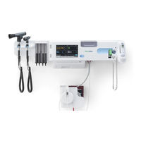
Welch Allyn Connex Service Manual (221 pages)
Integrated Wall System
Brand:
Welch Allyn
| Category:
Medical Equipment
| Size: 4 MB
Table of Contents
Table of Contents
3
Symbols
5
Safety
9
Warnings and Cautions
9
General Safety Considerations
10
Electrostatic Discharge (ESD)
10
Overview
13
Purpose and Scope
13
Technical Support Services
14
Recommended Service Intervals
18
The Welch Allyn Service Tool
18
Battery Performance
20
Factors Affecting Battery Operating Time
21
Controls, Indicators, and Connectors
23
Front View
23
Front Underside Views
24
Back View
25
Accessory bin
25
Mounting Materials
26
Service Menu
27
Access the Service Screens
27
General Tab
27
Restore Factory Default Settings
27
Save the Device Configuration or Custom Data to a Drive
28
Load a Device Configuration or Custom Data
28
Delete Custom Data
29
Self-Tests Tab
30
Logs Tab
30
Enter an Asset Tag
30
Calibrate the Touchscreen
30
Device Tab
31
Licensing Tab
31
Save Error and Event Logs to a USB Flash Drive
31
View Device and Module Information
31
Power-Up Sequence
33
Troubleshooting
35
Power Troubles
35
Symptoms and Solutions
35
Hardware Troubles
36
Display Troubles
37
Communication Troubles
38
User Interface Troubles
38
Alarms Troubles
40
NIBP Troubles
41
Spo2 Troubles
41
ECG Troubles
42
Sphb Troubles
42
Braun Thermoscan PRO 4000 Thermometer Troubles
44
Temperature Troubles
44
Weight Scale Troubles
44
Braun Thermoscan PRO 6000 Thermometer Troubles
45
Barcode Reader Troubles
47
Handles Troubles
47
Manual Parameters
47
Errors
48
NIBP Messages
49
Technical Alarm Messages
49
Spo2 and Sphb Messages
51
Temperature Messages (Suretemp)
52
Temperature Messages (Braun Thermoscan PRO)
53
ECG Messages
55
Communications Module Messages
57
Weight Scale Messages
57
Radio Messages
58
Ethernet Messages
59
USB Messages
59
Battery Power Manager Messages
60
System Messages
60
Configuration Manager Messages
61
Patient Data Management Messages
61
Network Messages
62
Disassembly and Repair
63
Required Tools and Equipment
65
Disassembly Overview
66
Power down the Device
67
Section a
67
Exploded View, Front Exterior
68
Replace Modules in the Bottom Housing
68
Reassembly Notes
69
Replace Modules in the Main Housing
70
Remove the Braun Dock from the Housing
71
Remove the System from the Wall and Remove the Battery
72
Remove the Light-Bar Board
73
Exploded View, Rear Interior
75
Remove the Handle Module Assembly
76
Remove the Handles
77
Remove the 767 Controller PCBA
77
Remove the Handle Cradle and Optical Assemblies
78
Open the Chassis
79
Exploded View, Chassis
82
Remove the Power Supply
82
Remove the Ground Lug, AC Power Harness Assembly, and IEC Connector
83
Remove the Communications Board
84
Remove the Radio Board and Antenna
85
Replace the Chassis
87
Disconnect or Remove the Light Bar
87
Disconnect or Remove the Fan
88
Disconnect or Remove the Power Panel
89
Remove the Speaker
91
Replace the Battery Board
91
Disconnect or Remove the Power Wire Harness and Main Wire Harness
92
Remove the Main Board
94
When Replacing the Main Board
96
Remove the LCD
96
When Replacing the LCD Frame
98
When Replacing the LCD
99
Remove Modules in the Bottom Housing
99
Remove the Module Well
101
Module USB Connectors
102
Replace the Power Button
103
Replace the Front Housing
103
Section B: Power down the Device
107
Exploded View, Front Exterior (Section B)
109
Replace Modules in the Bottom Housing (Section B)
109
Replace Modules in the Main Housing (Section B)
111
Remove the Braun Dock from the Housing (Section B)
112
Remove the System from the Wall and Remove the Battery (Section B)
113
Remove the Light-Bar Board (Section B)
114
Exploded View, Rear Interior (Section B)
116
Remove the Handle Module Assembly (Section B)
117
Remove the Handles (Section B)
118
Remove the 767 Controller PCBA (Section B)
118
Remove the Handle Cradle and Optical Assemblies (Section B)
119
Open the Chassis (Section B)
120
Number Item
121
Small 4-Pin Connector
121
Mini USB Cable
122
USB Cable
122
Ethernet Cable
122
Disconnect the Power Supply Cable from the Power Supply
122
Separate the Chassis from the Front Housing
122
Exploded View, Chassis (Section B)
124
Remove the Power Supply (Section B)
124
Remove Ground Lug/Ac Power Harness Assembly/And IEC Connector (Sec B)
125
Remove the Communications Board (Section B)
126
Remove the Radio Board and Antenna (Section B)
127
Replace the Chassis (Section B)
129
Disconnect or Remove the Light Bar (Section B)
129
Disconnect or Remove the Fan (Section B)
130
Disconnect or Remove the Power Panel (Section B)
131
Remove the Speaker (Section B)
133
Replace the Battery Board (Section B)
133
Disconnect/Remove Power Wire Harness and Main Wire Harness (Section B)
134
Remove the Main Board (Section B)
136
Remove the LCD (Section B)
139
When Replacing the LCD Frame (Section B)
141
When Replacing the LCD (Section B)
141
Remove Modules in the Bottom Housing (Section B)
142
Remove the Module Well (Section B)
143
Module USB Connectors (Section B)
145
Replace the Power Button (Section B)
145
Replace the Front Housing (Section B)
146
Functional Verification and Calibration
149
About the Welch Allyn Service Tool
149
Gold Licensed Edition Service Tool Tests Performed
150
Standard Unlicensed Edition Service Tool Tests Performed
150
Basic Functional Verification Check Tools
152
Basic Functional Verification Checks
152
Full Functional Verification Check and Calibration Tools
153
Create a Blood Pressure Y-Tube
154
NIBP Test Setup
154
NIBP Leak Test (Standard Unlicensed Edition)
155
NIBP Overpressure Test (Standard Unlicensed Edition)
155
NIBP Accuracy Check (Standard Unlicensed Edition)
156
Perform a Masimo Spo2 and Sphb Test
157
Perform a Nellcor Spo2 Test
157
Spo2 and Sphb Tests
157
Set up the 9600 Plus Calibration Tester
158
Suretemp Temperature Probe and System Test
158
Suretemp Temperature System Test
158
Braun Thermoscan PRO Thermometer Tests
159
Change the 9600 Plus Set Point
159
Perform a Suretemp Temperature Probe and System Test
159
Perform a Braun Thermoscan PRO 4000 Functional Verification Test
160
Perform a Braun Thermoscan PRO 6000 Functional Verification Test
161
ECG Functional Test
162
ECG Test Procedure
163
General Acceptance Criteria
163
Inspect the ECG Module and Cables
163
Perform a Basic Functional Test
165
Perform a Connection Test
165
163Electrical Safety Testing
167
Devices with an External Power Supply
167
Devices with an Internal Power Supply
168
Ground Stud Connector
168
Options, Upgrades, and Licenses
169
Available Options, Upgrades, and Licenses
170
Check the Connex Device Software Version
171
Check the Firmware Version on the Device
171
Check the Firmware Version Using the Service Tool
171
Install Options
172
Upgrade Software
172
Host Firmware Requirements
174
Activate Licenses
174
Masimo Parameter Upgrades
175
Configure Options
175
Field Replaceable Units
177
Front Housing, Handle Module Assembly, and Modules - Front Exterior Exploded View
177
Service Kits for both 2Nd-Edition and 3Rd-Edition Devices
178
Modules
178
Serv Kit, PLFM, LCD Display
181
Front Housing, Handle Housing, and Chassis - Rear Interior Exploded View
181
Chassis View
185
Handles Exploded View
187
Miscellaneous Parts
189
Licenses
190
Partners in Care Service and Support Agreements
190
Service and Repair Training
190
Decontamination and Cleaning Requirements
191
Appendices
191
Configuration Options
192
Factory Defaults
194
General Alarm Default Values
194
NIBP Default Values
195
Spo2 Default Values
196
Sphb Default Values
197
Temperature Default Values
197
Pulse Rate Default Values
198
RR Default Values
198
ECG Default Values
199
Patient Manual Parameters Default Values
200
Device Default Values
201
Data Management Default Values
202
Network Default Values
203
Disassembly and Repair Reference
205
Screws
205
Connector Types
206
Main Board Connectors
207
Battery Connector Board Connectors
209
Communications Board Connectors
210
Radio Board Connectors
211
Antenna Board Connectors
211
767 Controller Board Connectors
212
Power Supply Board Connectors
212
Connex Integrated Wall System Interconnect Diagram
213
Service Record
215
Advertisement
Welch Allyn Connex Directions For Use Manual (96 pages)
Central Station
Brand:
Welch Allyn
| Category:
Medical Equipment
| Size: 2 MB
Table of Contents
Table of Contents
3
Introduction
7
Intended Use
7
Related Documents
7
Symbols
9
About Warnings and Cautions
11
General Warnings and Cautions
11
System Configuration
15
Stand-Alone System Diagram
15
Server-Based System Diagram
16
Kiosk Diagram
17
Server-Only System Diagram
17
Screen Elements
19
Patient Tiles
20
Tile Layout Modes
25
Tile-Dragging Behavior
26
Device Details
27
Measurements Tab
27
Alarm Limits Tab
29
Patient List
31
Current Tab
31
Discharged Tab
33
Search Tab
34
Patient Details
35
Summary Tab
35
Contact Tab
37
Additional Tab
38
Patient Review
39
Flow Sheet Tab
39
Continuous Trends Tab
41
Graphical Trends Tab
43
Patient Alarms Tab
44
Views
47
View Selection Tab
47
View Configuration Tab
49
Patient Monitoring
51
Connect a Continuous Monitor to the Central Station
51
Connect an Episodic Device to the Central Station
52
Patient Data Management
53
Add a Patient at the Central Station
53
Admit a Patient from the Waiting Area
53
Admit a Patient from the Patient List
54
Admit a Patient from a Room Tile
54
Edit Patient Information at the Central Station
54
Edit Patient Information at the Device
54
Move a Patient
54
Assign a Patient to a Room
55
Review Patient Alarms
55
Transfer a Patient to a Different Unit Covered by the same Central Station
56
Transfer a Patient to a Different Unit Covered by a Different Central Station
56
Resolve an Information Message Conflict
56
Print the Patient List
57
End Monitoring a Patient
57
Discharge a Patient at the Central Station
57
Automatic Discharge
58
Re-Admit a Patient
58
Earlysense Sensor
59
Patient Tiles
59
Device Details - Measurements Tab
62
Device Details - Alarms Tab
64
Alarms
65
Pause an Alarm at the Central Station
70
Pause an Alarm at the Device
70
Adjust Patient Alarm Limits at the Central Station
70
Adjust Patient Alarm Limits at the Device
71
Test the Central Station Alarms
71
Alarm Messages and Priorities
72
Station Alarms
73
Station Alarms Window
73
Settings
75
Patient Rest Mode
75
Roles Tab
76
Devices Tab
77
Print Jobs Tab
79
Service Tools Tab
80
Admin Tools Tab
81
Station Settings Tab
82
Users Tab
84
General Maintenance
85
Central Station General Maintenance
86
Equipment Disposal
87
Troubleshooting
89
Display
89
Audio
89
Connectivity
90
Software
90
Guidance and Manufacturer's Declaration
91
EMC Compliance
91
Emissions and Immunity Information
91
Software License Agreement
93
Welch Allyn Connex Startup Manual (23 pages)
Integrated Wall System
Brand:
Welch Allyn
| Category:
Medical Equipment
| Size: 3 MB
Table of Contents
Unpack the Wall System
5
Insert the Battery
7
Prepare for Mounting
8
Mounting Location
9
Mount the Wall System
10
Mount the Accessory bin
15
Connect the Blood Pressure (NIBP) Hose
16
Set up the Physical Assessment Instrument Handles and Specula Dispenser
17
Set up the Suretemp® Plus Thermometer
18
Connect Ac Power
20
Select a Language
21
Set the Date and Time
22
Set the Default Configuration
22
Advertisement
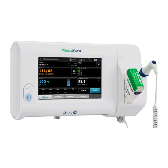
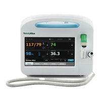
Welch Allyn Connex Quick Reference Manual (2 pages)
Patient Monitor
Brand:
Welch Allyn
| Category:
Medical Equipment
| Size: 1 MB
Advertisement
Related Products
Welch Allyn Connex IWS
Welch Allyn Connex Spot Monitor
Welch Allyn Connex Vital Signs Monitor
Welch Allyn Connex Integrated Wall System
Welch Allyn CARDIOPERFECT
Welch Allyn CP 50 Plus
Welch Allyn CP 20
Welch Allyn CSM 7300
Welch Allyn CP10 ECG
Welch Allyn CL 300
Welch Allyn Categories
Medical Equipment
Lighting Equipment
Thermometer
Measuring Instruments
Scales
More Welch Allyn Manuals
Login
Sign In
OR
Sign in with Facebook
Sign in with Google
Upload manual
Upload from disk
Upload from URL