Welch Allyn Connex Service Manual
Integrated wall system
Hide thumbs
Also See for Connex:
- Directions for use manual (96 pages) ,
- Startup manual (23 pages) ,
- Quick reference manual (2 pages)
Table of Contents
Advertisement
Advertisement
Table of Contents

Related Manuals for Welch Allyn Connex


Summary of Contents for Welch Allyn Connex
- Page 1 ® Welch Allyn Connex Integrated Wall System Service manual Software version 2.3X...
- Page 2 © 2018 Welch Allyn. All rights are reserved. To support the intended use of the product described in this publication, the purchaser of the product is permitted to copy this publication, for internal distribution only, from the media provided by Welch Allyn. No other use, reproduction, or distribution of this publication, or any part of it, is permitted without written permission from Welch Allyn.
-
Page 3: Table Of Contents
Overview ....................9 Purpose and scope ....................9 Technical support services ................. 10 Recommended service intervals ................ 14 The Welch Allyn Service Tool ................14 Battery performance ..................16 Controls, indicators, and connectors ........... 19 Service menu ..................23 Access the Service screens ................23 General tab ...................... -
Page 4: Table Of Contents
Service and repair training ................186 Appendices ..................187 Decontamination and cleaning requirements ..........187 Configuration options ..................188 Factory defaults ....................190 Disassembly and repair reference ..............201 Connex Integrated Wall System interconnect diagram ........209 Service record ....................211... -
Page 5: Symbols
Follow the operating instructions/directions for use (DFU) — mandatory action. A copy of the DFU is available on this website. A printed copy of the DFU can be ordered from Welch Allyn for delivery within 7 days. Power symbols Power on/Display power-saving... - Page 6 ® Symbols Welch Allyn Connex Integrated Wall System (on the monitor, green indicator) Battery charge level Alternating Current power present, battery fully charged (on the monitor, amber indicator) Battery cover Alternating Current power present, battery is charging Alternating Current (AC)
- Page 7 Service manual Symbols 3 Nonionizing electromagnetic Recycle the product separate from radiation other disposables Restrictions for use of wireless Call for maintenance device in Europe. European Community's Class 2 radio equipment. Defibrillation-proof Type BF applied Defibrillation-proof Type CF applied parts parts Atmospheric pressure limitation Not for injection...
- Page 8 ® Symbols Welch Allyn Connex Integrated Wall System...
-
Page 9: Safety
Safety All users of the system must read and understand all safety information presented in this manual before using or repairing the system. United States federal law restricts this device to sale, distribution, or use by or on the order of a licensed medical practitioner. Warnings and cautions WARNING Safety risk. -
Page 10: General Safety Considerations
• To ensure patient safety, use only accessories recommended or supplied by Welch Allyn. (See the accessories list in the Welch Allyn Connex Integrated Wall System Directions for use on the user documentation CD or http://www.welchallyn.com. Always use accessories according to your facility’s standards and according to the manufacturer’s recommendations and instructions. - Page 11 Service manual Safety 7 • Remove static-sensitive components and assemblies from their static-shielding bags only at static-safe workstations—a properly grounded table and grounded floor mat— and only when you are wearing a grounded wrist strap (with a resistor of at least 1 megohm in series) or other grounding device.
- Page 12 ® 8 Safety Welch Allyn Connex Integrated Wall System...
-
Page 13: Overview
Purpose and scope This manual is a reference for periodic preventive maintenance and corrective service procedures for the Welch Allyn Connex Integrated Wall System, firmware version 2.3X. It is intended for use only by trained and qualified service personnel. Corrective service is supported to the level of field-replaceable units. These include circuit-board assemblies and some subassemblies, case parts, and other parts. -
Page 14: Technical Support Services
Partners in Care service agreements While product warranties provide basic assurance of Welch Allyn hardware quality, they may not include the full range of services and support you need. Welch Allyn offers premium service and support through our Partners in Care program. Whether you service your own devices and require a minimum of support or rely on us to service your device, Welch Allyn provides a program that will meet your needs. - Page 15 Qualified service personnel or a Welch Allyn Service Center should repair products out of warranty. If you are advised to return a product to Welch Allyn for repair or routine maintenance, schedule the repair with the service center nearest you.
- Page 16 Welch Allyn does not accept returned products without an Note RMA. 2. Ship the device to Welch Allyn, observing these rules: a. Remove from the package the battery, all hoses, connectors, cables, sensors, power cords, and other ancillary products and equipment, except those items that might be associated with the problem.
- Page 17 Remember that the device and any batteries must be packed and shipped separately. e. Write the Welch Allyn RMA number with the Welch Allyn address on the outside of the shipping carton. WARNING Safety risk. Do not ship any battery that has...
-
Page 18: Recommended Service Intervals
To confirm that the device is functioning within the design specifications, perform periodic service as indicated in the following table. Customers who have the Standard unlicensed edition of the Welch Allyn Service Tool can perform the basic functional verification and calibration procedures referenced in the table by following the instructions in this manual. - Page 19 Welch Allyn technical training course or complete online training for the device. Clinicians and technical service personnel can use the service tool to manage and maintain supported Welch Allyn products. You can use the service tool to do the following: •...
-
Page 20: Battery Performance
® 16 Overview Welch Allyn Connex Integrated Wall System Battery performance About the battery The battery in the wall system provides backup power during a power Note outage, not power for normal use. Except during cleaning and maintenance activities, the wall system should remain connected to AC power at all times. - Page 21 Service manual Overview 17 Factors affecting battery operating time The following settings and conditions affect the battery operating time: • The display brightness setting • The display power-saver setting • The device power-down setting • Frequency and duration of alarms and alerts •...
- Page 22 ® 18 Overview Welch Allyn Connex Integrated Wall System...
-
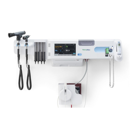
Page 23: Controls, Indicators, And Connectors
No. Feature Description Physical assessment instruments - Handles Handles accept any 3.5V Welch Allyn instrument head. and handle cradles Handle cradles support using one handle at a time. A handle turns on automatically when you remove it from a cradle and turns off when you return it. - Page 24 ® 20 Controls, indicators, and connectors Welch Allyn Connex Integrated Wall System No. Feature Description Braun ThermoScan® PRO thermometer and Support temperature measurements from the ear. Dock charges dock the thermometer battery. SureTemp® Plus thermometer connector Secures the probe connection to the wall system.
- Page 25 Service manual Controls, indicators, and connectors 21 No. Feature Description Ground lug (equipotential terminal) Supports electrical safety testing; terminal for connecting a potential equalization conductor. USB connectors Provides access to host USB connections for optional accessories. USB cable retainer Reduces strain on USB cables and connectors; helps prevent cables from disconnecting.
- Page 26 ® 22 Controls, indicators, and connectors Welch Allyn Connex Integrated Wall System Mounting materials No. Feature Description Wall mounting rail bracket and hardware Secures the wall system to the wall. Accessory bin mounting bracket and Secure accessory bin to the wall and provide routing and strain hardware relief for power cord.
-
Page 27: Service Menu
Service menu The Service tab is located inside Advanced settings. The Advanced tab provides password-protected access to the monitor's Advanced settings (or Admin mode), enabling nurse administrators, biomedical engineers, and/or service engineers to configure specific features. The Advanced tab also presents read-only information about the monitor. - Page 28 ® 24 Service menu Welch Allyn Connex Integrated Wall System 1. Go to the Service screens as described in “Access the Service screens.” 2. Touch the General tab. 3. Restore factory default settings: • To restore radio settings to factory default values, touch Radio settings.
- Page 29 Service manual Service menu 25 Not all flash drives are supported. Note Note If your configuration includes radio parameters, make sure the radio is enabled. The radio must be enabled before you can import radio parameters. If a device setting is not available in the configuration file, the setting Note returns to the factory default.
-
Page 30: Self-Tests Tab
® 26 Service menu Welch Allyn Connex Integrated Wall System Enter an asset tag You can enter an alpha-numeric identifier in the data field to serve as an asset tag for device identification. 1. Go to the Service screens as described in “Access the Service screens.”... -
Page 31: Device Tab
Service manual Service menu 27 Save error and event logs to a USB flash drive This feature is available in software versions 1.71.03 and later. You can save a copy of the error and event logs to a USB flash drive. Note Not all flash drives are supported. - Page 32 ® 28 Service menu Welch Allyn Connex Integrated Wall System...
-
Page 33: Power-Up Sequence
2. Insert a fully charged battery into the device. 3. Upon each power up, confirm the following: a. The light bar flashes amber. b. The Welch Allyn startup screen appears. c. A beep sounds, followed by one chime. Note If no chimes sound, replace the speaker as specified in “Replace the speaker.”... - Page 34 ® Power-up sequence Welch Allyn Connex Integrated Wall System...
-
Page 35: Troubleshooting
AC power and call Welch Allyn Technical Support immediately. CAUTION Replace parts, components, or accessories only with parts supplied or approved by Welch Allyn. The use of any other parts can lead to inferior performance and will void the product warranty. Symptoms and solutions... - Page 36 ® 32 Troubleshooting Welch Allyn Connex Integrated Wall System Symptom Possible cause Suggested action An internal connection is faulty Check the power-flex cable connection at J6 on the main board. Check the AC power harness connections from the IEC connector to the power supply.
- Page 37 Service manual Troubleshooting 33 Mechanical Symptom Possible cause Suggested action Cracks in housing Non-approved cleaning agents Replace plastic housing as necessary. Use only approved cleaning agents. Display Symptom Possible cause Suggested action The touchscreen does not respond Software error Reboot the device. Press and hold the power button until the device shuts down.
-
Page 38: User Interface
® 34 Troubleshooting Welch Allyn Connex Integrated Wall System Symptom Possible cause Suggested action J19 on the main board. Replace the cable if damaged. A cable is damaged Replace the cable. The display is dim The brightness setting is too low Increase the brightness setting. - Page 39 Service manual Troubleshooting 35 Symptom Possible cause Suggested action communicate with the device. See the service tool help files. Replace the power cable to the communications board. USB accessories do not The accessory is defective Replace with a known good communicate with the monitor accessory.
- Page 40 ® 36 Troubleshooting Welch Allyn Connex Integrated Wall System Symptom Possible cause Suggested action The communications board is not receiving power Check the voltage from J49 on the main board for +5.0, ±0.5V DC. Replace the main board if necessary.
- Page 41 Check the error logs for NIBP errors. See the service tool help files for details on specific errors and suggested actions. Check with Welch Allyn for software updates. If no NIBP error is logged, the main board might Replace the main board if be defective necessary.
- Page 42 ® 38 Troubleshooting Welch Allyn Connex Integrated Wall System SpHb Symptom Possible cause Suggested action The SpHb frame on the display is The UI license is not installed. Purchase a license and install the blank license using the service tool.
- Page 43 ECG vertical tab. Enable Patient has a pacemaker. ECG module unable to detect pacer Contact Welch Allyn Technical Support. Replace the module if necessary. No alarming snapshot was auto- Automatic print on ECG alarm disabled...
- Page 44 ® 40 Troubleshooting Welch Allyn Connex Integrated Wall System Weight scale Symptom Possible cause Suggested action Weight does not appear in manual The weight was not selected in Advanced In Advanced settings, touch the parameter frame settings Parameters tab, then select Weight.
- Page 45 Service manual Troubleshooting 41 Symptom Possible cause Suggested action Thermometer readings do not The external USB cable is unplugged Check the external USB transfer to the device connection. The USB bus has stopped communicating with Reboot the host device. the Braun dock. (The device displays wrench error #00000014.) For additional troubleshooting tips for the thermometer, see the Note...
- Page 46 C/F button or return to the dock while holding the C/F button. Retry upgrade. *Host device Braun 6000 settings override configuration settings from Welch Allyn Service Tool. Note For additional troubleshooting tips for the thermometer, see the manufacturer’s product documentation.
- Page 47 For Honeywell model 4600g barcode readers, verify that the PID is set to 020A. The barcode scanner did not enumerate properly Power cycle the Connex device. The patient ID or clinician ID do not The barcode scanner is not programmed to properly...
- Page 48 Note The GS 777 Wall Transformer will accommodate instrument heads of the Welch Allyn approved Halogen and LED type bulbs without any manual adjustment. For information about instrument heads, follow the instructions provided in their directions for use.
-
Page 49: Technical Alarm Messages
Service manual Troubleshooting 45 Symptom Possible cause Suggested action #000000010 An Ethernet system error #000000011 The touchscreen controller failed #000000012 Five or more SMBUS errors over a 1-minute period occurred #000000013 The communications module or main board failed #000000014 Main board USB hub failure #000000015 Software watchdog timer reset Technical alarm messages... - Page 50 Check the error logs for NIBP service. errors. See the service tool help files for details on specific errors and suggested actions. Check with Welch Allyn for software updates. The ambient temperature is out of range Use the monitor in the specified temperature range.
- Page 51 Check the error logs for SpO2 errors. See the service tool help files for details on specific errors and suggested actions. Check with Welch Allyn for software updates. Attach SpO2 sensor to monitor. The sensor was not detected Check the sensor connection.
- Page 52 ® 48 Troubleshooting Welch Allyn Connex Integrated Wall System Message Possible cause Suggested action Low SpHb signal quality. Check The patient cable or sensor is defective Replace the patient cable or sensor. sensor. Low perfusion. Check sensor. The SpO2 module is faulty...
- Page 53 Service manual Troubleshooting 49 Message Possible cause Suggested action engaging switch SW1 on the temperature PCBA. If the problem persists, replace the module. Replace temperature probe. The probe is faulty Replace the temperature probe. The SureTemp temperature module is faulty Verify module functionality by replacing the temperature probe with the CAL-KEY assembly.
- Page 54 ® 50 Troubleshooting Welch Allyn Connex Integrated Wall System Message Possible cause Suggested action Recharge or replace battery. Dead battery Braun display is blank or battery icon shows one Braun displays “POS” error Change the probe cover to reset. Restrict patient movement and...
- Page 55 See the service tool help files for details on specific errors and suggested actions. Check with Welch Allyn for software updates. The USB cable is disconnected Check the USB cable. The battery is depleted or missing Replace the batteries.
- Page 56 Suggested action ECG module disconnected Check the ECG module connection to Connex device. Unexpected alarm compatibility bits Restart the Connex device and the ECG module; if the error persists, contact Customer Care. Perform functional test. If the test fails, contact...
- Page 57 Service manual Troubleshooting 53 Message Possible cause Suggested action You are not using Lead II to view Ensure that you are respiration viewing Lead II for respiration. Attempting to acquire ECG/Impedance Check electrodes and respiration leads, and replace as needed. Check the patient cable connection to the ECG module.
- Page 58 ® 54 Troubleshooting Welch Allyn Connex Integrated Wall System Radio messages Message Possible cause Suggested action Alarm Radio not functional. Call for A hardware failure occurred Replace the radio. service. The radio has the wrong software Update the radio software.
- Page 59 A device requiring a license has been connected Obtain an authorization code use. to the USB connection from Welch Allyn to activate the license. Unable to save configuration to There was a problem writing the configuration Use a Welch Allyn approved USB.
-
Page 60: System Messages
® 56 Troubleshooting Welch Allyn Connex Integrated Wall System System messages Message Possible cause Suggested action Alarm Set date and time. The date or time is not set Set the date and time. The date or time is not set properly Reset the date or time. - Page 61 Service manual Troubleshooting 57 Configuration Manager messages Message Possible cause Suggested action Alarm Unable to load configuration; using A configuration load error occurred Restore factory defaults. If the factory defaults. error persists, replace the main board. Functional error. Call for service. A critical configuration load error occurred Replace the main board.
- Page 62 ® 58 Troubleshooting Welch Allyn Connex Integrated Wall System Message Possible cause Suggested action Stop intervals to select new The device is set to take interval readings Stop intervals before changing patient. the patient. No connection for send. No connectivity is available to support sending Check the network connection.
-
Page 63: Disassembly And Repair
Disassembly and repair This chapter is divided into two major subsections, defined in the table below. Section A Section B (IEC 60601 3rd-edition compliant) Devices meeting these criteria: Devices meeting these criteria: • Manufactured before 12/2017* • Manufactured after 12/2017* •... - Page 64 For more information about these tests and the service tool, see “Functional verification and calibration.” If you do not have the service tool, contact Welch Allyn Technical Support. For information about screws or connectors used in the device, see the Appendix.
-
Page 65: Required Tools And Equipment
Service manual Disassembly and repair 61 Required tools and equipment • #1 Phillips bit • #2 Phillips bit • #10 Torx bit • Torque driver calibrated for 6.0 in-lb ±1.0 in-lb • Torque driver calibrated for 7.5 in-lb ±0.5 in-lb •... -
Page 66: Disassembly Overview
® 62 Disassembly and repair Welch Allyn Connex Integrated Wall System Disassembly overview The following chart provides an overview of the complete disassembly of the device. Most disassembly activities require that you complete a subset of the steps detailed here. The flow chart indicates the steps that must be completed in sequence to remove a particular component. -
Page 67: Section A
Section A This section applies to devices manufactured before 12/2017, serial numbers before 100023374817, and MCE hardware version P3 or earlier. Note If your device does not meet these criteria, see Section B for the correct disassembly and repair instructions. If the MCE hardware version is P2 or P3, DO NOT replace any components with service kits with the "3rd Ed"... -
Page 68: Exploded View, Front Exterior
® 64 Section A Welch Allyn Connex Integrated Wall System Exploded view, front exterior Item Item Side housing Power button SureTemp module Blue insert CIWS handle module assembly NIBP module Braun housing SpO2 module Platform module, blank Braun dock Module cover... - Page 69 Service manual Section A 65 4. Remove the module cover. Loosen the captive screw using a #2 Phillips screwdriver to remove the module cover. Note The modules fit tightly in the housing but can become loose over time. Support the modules to prevent them from falling out as you remove the module cover.
- Page 70 ® 66 Section A Welch Allyn Connex Integrated Wall System Replace modules in the main housing Note Check how the end cap or Braun thermometer housing are attached to the device. If bushings with captive screws attach the end cap or Braun thermometer housing to the side of the main housing as shown in step 1, proceed with the instructions as presented.
- Page 71 Service manual Section A 67 6. If SureTemp is installed, remove the module and the probe cover storage together, sliding them out the open end, and disconnect the USB cable. 7. Slide any blank face plates or modules to be removed toward the open end. Note When removing any connected modules, disconnect the USB cables before you remove the module.
- Page 72 ® 68 Section A Welch Allyn Connex Integrated Wall System • When replacing the Braun dock, insert the bottom of the dock into the housing, align the molded ridges in the top of the dock with the slots in the top of the housing, and snap the dock into the housing.
- Page 73 Service manual Section A 69 8. Remove the wall anchor screws using a #2 Phillips screwdriver. 9. Hold the bottom and top of the system and push it up to remove the system from the wall mounting bracket. 10. Place the wall system on a table or flat work surface so that the back of the wall system faces up.
- Page 74 ® 70 Section A Welch Allyn Connex Integrated Wall System 3. Remove the light bar from the light-bar cover. 4. Disconnect the light-bar harness from the light-bar board. 5. Remove the light-bar board from the light bar by sliding the board out from the connector end.
-
Page 75: Exploded View, Rear Interior
Service manual Section A 71 Exploded view, rear interior Item Item LCD with touchscreen LCD bezel Main board LCD frame Main housing Chassis Platform fan assembly Cable, USB client Platform speaker assembly Handle assembly Module well assembly PCBA: Platform 767 controller, pattern E Light bar Handle, cradle, and opticals assembly, cool blue Power panel... - Page 76 ® 72 Section A Welch Allyn Connex Integrated Wall System Item Item Battery connector Screw, Plastite #4-20 x .500 Pan head (Torx screw) Power button and flex cable CCH44-S10 P-clamp, 0.437 Blue insert Remove the handle module assembly Complete the following preliminary steps: •...
- Page 77 Service manual Section A 73 Remove the handles Complete the following preliminary steps: • Power down the system and disconnect the AC power cord. • Remove the system from the wall and remove the battery. • Remove the handle module assembly. 1.
- Page 78 ® 74 Section A Welch Allyn Connex Integrated Wall System • Remove the handle module assembly. • Remove the handles. 1. Disconnect the two IR wire connectors from the handle PCBA. 2. Remove the three Torx screws. 3. Lift and remove the PCBA.
- Page 79 Service manual Section A 75 Reassembly notes • For ease of assembly, connect the IR wire assemblies to the optical sensors before attaching the handle cradle to the handle assembly housing. • Attach the connector with the black and white wires to the optical detector (indicated by the letter "B"...
- Page 80 ® 76 Section A Welch Allyn Connex Integrated Wall System • For systems built before July 15, 2011 with the Braun thermometer option or end cap mounted to the rear chassis: a. Remove the 6 screws as shown. b. Disconnect the USB cable from the rear of the Braun housing.
- Page 81 Service manual Section A 77 Number Item Small 4-pin connector Mini USB cable USB cable Ethernet cable 4. Disconnect the power supply cable from the power supply. 5. Separate the chassis from the front housing.
- Page 82 ® 78 Section A Welch Allyn Connex Integrated Wall System Exploded view, chassis Item Item Chassis Radio board Screw, M3 x 0.5, Pan Phillips (Small Phillips screw) 57 Antenna board Screw, Plastite #4-20 x .500 Pan head (Torx screw) 58...
- Page 83 Service manual Section A 79 2. Remove the four torx screws. 3. Remove the power supply. Reassembly note When reinstalling the power supply, orient the board so that the end of the board with the AC-to-power-supply (J1) connection is closest to the IEC connector. Remove the ground lug, AC power harness assembly, and IEC connector Note Do not disconnect the AC power harness from the IEC connector unless...
- Page 84 ® 80 Section A Welch Allyn Connex Integrated Wall System a. Remove the 10mm hex nut and slide out the star lock washer and the ground wire (power supply) ring terminal. b. Remove the next 10 mm hex nut and slide out the star lock washer, the ground wire (mains) ring terminal, and the flat washer.
- Page 85 Service manual Section A 81 2. Turn over the chassis to access the communications board. 3. Remove the four Torx screws. 4. Lift the communications board from the chassis. 5. For systems with the radio option, remove the tape securing the antenna cable, and rotate the communications board counter-clockwise to clear the chassis.
- Page 86 ® 82 Section A Welch Allyn Connex Integrated Wall System c. Hold the communications board with one hand while grasping the radio board at the opposite end from the antenna connection and pull the radio board away from the communications board.
- Page 87 Service manual Section A 83 • Once the antenna, radio, and communications board are mounted and secure, secure the antenna cable to the housing with Pro Gaff tape. Replace the chassis Complete the following preliminary steps: • Power down the system and disconnect the AC power cord. •...
- Page 88 ® 84 Section A Welch Allyn Connex Integrated Wall System 2. Remove the light bar and cover. 3. Remove the light bar from the light-bar cover. 4. Disconnect the light-bar harness from the light-bar board. 5. If replacing the light-bar board, remove the light-bar board from the light bar by sliding the board out from the connector end.
- Page 89 Service manual Section A 85 • Open the chassis. 1. Disconnect the power cable from the fan harness connector. 2. Press the flanges on the sides of the fan harness connector and separate the fan connector from the power panel. 3.
- Page 90 ® 86 Section A Welch Allyn Connex Integrated Wall System • Remove the fan. 1. If you haven't done so already, disconnect the power cable from the fan harness connector. 2. Disconnect the two harness connectors from the battery board.
- Page 91 Service manual Section A 87 5. Pull the module handle assembly USB cable through the access hole in the power panel. Reassembly notes • Pull the module handle assembly USB cable through the access hole in power panel before securing the power panel to the housing. •...
- Page 92 ® 88 Section A Welch Allyn Connex Integrated Wall System 3. Secure the new battery board to the battery compartment with two Torx screws. Disconnect or remove the power wire harness and main wire harness Note If removing the main board or LCD, it is not necessary to cut wire ties attaching the harness to the housing unless you are replacing the harness or the housing.
- Page 93 Service manual Section A 89 3. If you are replacing the power harness, carefully cut the two wire ties and remove the harness. 4. If you are replacing the main harness, disconnect the main harness from the power panel, carefully cut the two wire ties, and remove the harness. Reassembly notes When replacing the harness standoff: •...
- Page 94 ® 90 Section A Welch Allyn Connex Integrated Wall System • Align the shrink-wrapped sections with the wire tie anchors. • Align the end with the wire tie closest to the end on the left to connext with the main board.
- Page 95 Service manual Section A 91 3. Remove the seven small Phillips screws that secure the main board to the LCD frame. 4. Remove the main board. Reassembly notes • Ensure that the LCD flex cable is not under the main board. CAUTION The solder joint of the LCD connector (J48) is fragile.
- Page 96 Enter the device’s serial number. This can be found on the bottom of the device. ○ Enter the main board (host controller) serial number. ○ Select the Connex Integrated Wall System from the device model dropdown menu. ○ Restore any previously licensed features by entering the authorization code in the service tool.
- Page 97 Service manual Section A 93 Do not remove the LCD harness from the frame unless you are replacing Note the harness or frame. 1. Remove the tape and disconnect the LCD harness from the LCD. For easier access to the connector, you can slide the ferrite bead closest to the connector up the harness.
- Page 98 ® 94 Section A Welch Allyn Connex Integrated Wall System • Center the LCD and bezel in the main housing's molded channel with the bottom near the screw bosses. • Replace the Pro Gaff tape in the frame opening under the display harness as shown.
- Page 99 Service manual Section A 95 When replacing the LCD • Peel the protective sheet from the LCD. • Verify that the foam strips are installed on the back of the LCD near the top and bottom edges. On 1st generation displays (see image on the left), the foam strip extends halfway up from the bottom on both sides of the LCD.
- Page 100 ® 96 Section A Welch Allyn Connex Integrated Wall System 2. Disconnect the NIBP hose and the SpO2 cable if present. 3. Remove the communications cover housing. Loosen the two captive screws using a #2 Phillips screwdriver to remove the communications cover.
- Page 101 Service manual Section A 97 Reassembly notes • When aligning the module with the housing, the USB connection is on the left. • The NIBP module must always be in the front-most slot. Remove the module well Option 1. Complete the following preliminary steps if your goal is to replace the front housing: •...
- Page 102 ® 98 Section A Welch Allyn Connex Integrated Wall System 3. Remove the module well from the front housing. Remove the attached USB cables if necessary. Reassembly notes • Route USB cables properly: ○ Route cables through the module well to the correct corresponding module.
- Page 103 Service manual Section A 99 USB slot Material number Connection 712980 MCE to communications board none 715891 MCE to handle module PCBA 713282 MCE to communications Replace the power button Complete the following preliminary steps: • Power down the system and disconnect the AC power cord. •...
- Page 104 ® 100 Section A Welch Allyn Connex Integrated Wall System • Remove the power panel. • Remove the power wire harness and the main wire harness. • Remove the modules in the bottom housing. • Remove the module well. 1. Disconnect all USB connections from the main board.
- Page 105 Service manual Section A 101 6. Carefully lift the LCD and the attached main board from the housing. CAUTION Support the LCD as you lift the assembly from the housing. The LCD is not secured to the assembly. 7. Remove the two module tracks by removing the four Torx screws.
- Page 106 ® 102 Section A Welch Allyn Connex Integrated Wall System...
-
Page 107: Section B
Section B This section applies to devices that meet all of the following criteria: • manufactured after 12/2017 • MCE hardware version P5 or later • serial number after 100023374817. These devices comply with IEC 60601 3rd edition. If your device does not meet these criteria, see Section A for the correct Note disassembly and repair instructions. - Page 108 ® 104 Section B Welch Allyn Connex Integrated Wall System Option 2. To use onscreen controls alone to power down the device, follow these steps: 1. Touch the Settings tab. 2. Touch the Device tab. 3. Touch Power down. Note...
- Page 109 Service manual Section B 105 Exploded view, front exterior Item Item Side housing Power button SureTemp module Blue insert CIWS handle module assembly NIBP module Braun housing SpO2 module Platform module, blank Braun dock Module cover Strain relief, comms, PW Communications cover housing Ear speculum dispenser, small Cubby door...
- Page 110 ® 106 Section B Welch Allyn Connex Integrated Wall System 4. Remove the module cover. Loosen the captive screw using a #2 Phillips screwdriver to remove the module cover. Note The modules fit tightly in the housing but can become loose over time.
- Page 111 Service manual Section B 107 Replace modules in the main housing Note Check how the end cap or Braun thermometer housing are attached to the device. If bushings with captive screws attach the end cap or Braun thermometer housing to the side of the main housing as shown in step 1, proceed with the instructions as presented.
- Page 112 ® 108 Section B Welch Allyn Connex Integrated Wall System 6. If SureTemp is installed, remove the module and the probe cover storage together, sliding them out the open end, and disconnect the USB cable. 7. Slide any blank face plates or modules to be removed toward the open end.
- Page 113 Service manual Section B 109 • When replacing the Braun dock, insert the bottom of the dock into the housing, align the molded ridges in the top of the dock with the slots in the top of the housing, and snap the dock into the housing.
- Page 114 ® 110 Section B Welch Allyn Connex Integrated Wall System 8. Remove the wall anchor screws using a #2 Phillips screwdriver. 9. Hold the bottom and top of the system and push it up to remove the system from the wall mounting bracket.
- Page 115 Service manual Section B 111 3. Remove the light bar from the light-bar cover. 4. Disconnect the light-bar harness from the light-bar board. 5. Remove the light-bar board from the light bar by sliding the board out from the connector end. Reassembly notes •...
- Page 116 ® 112 Section B Welch Allyn Connex Integrated Wall System Exploded view, rear interior Item Item LCD with touchscreen LCD bezel Main board LCD frame Main housing Chassis Platform fan assembly Cable, USB client Platform speaker assembly Handle assembly Module well assembly...
- Page 117 Service manual Section B 113 Item Item Battery connector Screw, Plastite #4-20 x .500 Pan head (Torx screw) Power button and flex cable CCH44-S10 P-clamp, 0.437 Blue insert Remove the handle module assembly Complete the following preliminary steps: • Power down the system and disconnect the AC power cord. •...
- Page 118 ® 114 Section B Welch Allyn Connex Integrated Wall System Remove the handles Complete the following preliminary steps: • Power down the system and disconnect the AC power cord. • Remove the system from the wall and remove the battery.
- Page 119 Service manual Section B 115 • Remove the handle module assembly. • Remove the handles. 1. Disconnect the two IR wire connectors from the handle PCBA. 2. Remove the three Torx screws. 3. Lift and remove the PCBA. Reassembly note When reconnecting the IR wire connectors to the handle PCBA, the connecting wires must be facing down and toward the cradle assemblies.
- Page 120 ® 116 Section B Welch Allyn Connex Integrated Wall System Reassembly notes • For ease of assembly, connect the IR wire assemblies to the optical sensors before attaching the handle cradle to the handle assembly housing. • Attach the connector with the black and white wires to the optical detector (indicated by the letter "B"...
- Page 121 Service manual Section B 117 3. Remove the two Torx screws securing the client USB connector to the housing, and then disconnect and remove the cable. CAUTION Multiple wire connections are still connected between the front housing and the chassis. These must be disconnected before it is safe to completely separate the two pieces.
- Page 122 ® 118 Section B Welch Allyn Connex Integrated Wall System Number Item Mini USB cable USB cable Ethernet cable 5. Disconnect the power supply cable from the power supply. 6. Separate the chassis from the front housing enough to make the AC power harness ground connection reach the dual spade connector.
- Page 123 Service manual Section B 119 • Install the screws to secure the front housing to the chassis.
- Page 124 ® 120 Section B Welch Allyn Connex Integrated Wall System Exploded view, chassis Item Item Chassis Radio board Screw, M3 x 0.5, Pan Phillips (Small Phillips screw) 57 Antenna board Screw, Plastite #4-20 x .500 Pan head (Torx screw) 58...
- Page 125 Service manual Section B 121 2. Remove the four Torx screws. 3. Remove the power supply. Reassembly note When reinstalling the power supply, orient the board so that the end of the board with the AC-to-power-supply (J1) connection is closest to the IEC connector. Remove the ground lug, AC power harness assembly, and IEC connector Note Do not disconnect the AC power harness from the IEC connector unless...
- Page 126 ® 122 Section B Welch Allyn Connex Integrated Wall System 2. To remove the ground lug: a. Remove the 10mm hex nut and slide out the star lock washer and the ground wire (power supply) ring terminal. b. Remove the next 10 mm hex nut and slide out the star lock washer, the ground wire (mains) ring terminal, and the flat washer.
- Page 127 Service manual Section B 123 • Power down the system and disconnect the AC power cord. • Remove the system from the wall and remove the battery. • Remove the handle module assembly. • Open the chassis. 1. Disconnect the mini-USB connection on the outside of the chassis. 2.
- Page 128 ® 124 Section B Welch Allyn Connex Integrated Wall System Complete the following preliminary steps: • Power down the system and disconnect the AC power cord. • Remove the system from the wall and remove the battery. • Remove the handle module assembly.
- Page 129 Service manual Section B 125 • Clean the chassis and mounting surface with 70 percent isopropyl alcohol. • Peel the backing off the double-stick tape and affix it to the chassis antenna plate. • Mount the antenna to the antenna plate. Make sure the PG terminal on the antenna board is facing outwards.
- Page 130 ® 126 Section B Welch Allyn Connex Integrated Wall System • Remove the handle module assembly. • Open the chassis. 1. Remove the two Torx screws from the light-bar cover. 2. Remove the light bar and cover. 3. Remove the light bar from the light-bar cover.
- Page 131 Service manual Section B 127 • Power down the system and disconnect the AC power cord. • Remove the system from the wall and remove the battery. • Remove the handle module assembly. • Open the chassis. 1. Disconnect the power cable from the fan harness connector. 2.
- Page 132 ® 128 Section B Welch Allyn Connex Integrated Wall System • Remove the system from the wall and remove the battery. • Remove the handle module assembly. • Open the chassis. • Remove the fan. 1. If you haven't done so already, disconnect the power cable from the fan harness connector.
- Page 133 Service manual Section B 129 5. Pull the module handle assembly USB cable through the access hole in the power panel. Reassembly notes • Pull the module handle assembly USB cable through the access hole in power panel before securing the power panel to the housing. •...
- Page 134 ® 130 Section B Welch Allyn Connex Integrated Wall System 2. Remove the two Torx screws from the battery compartment and remove the battery board. 3. Secure the new battery board to the battery compartment with two Torx screws. Disconnect or remove the power wire harness and main wire harness...
- Page 135 Service manual Section B 131 2. Disconnect the connectors as follows: • To disconnect the power harness, disconnect the connectors at J29 and J30. • To disconnect the main harness, disconnect the connectors at J34, J12, J49, J46, and J45. 3.
- Page 136 ® 132 Section B Welch Allyn Connex Integrated Wall System • Attach the harness to the main housing using the wire tie anchors closest to the display or front of the housing. When replacing the power harness: • Align the shrink-wrapped sections with the wire tie anchors.
- Page 137 Service manual Section B 133 a. Disconnect the Ethernet cable from the Ethernet cable connector at J11 on the main board. b. Remove the screw that secures the Ethernet cable P-clamp to the main board. c. Remove the Ethernet cable. 3.
- Page 138 Enter the device’s serial number. This can be found on the bottom of the device. ○ Enter the main board (host controller) serial number. ○ Select the Connex Integrated Wall System from the device model dropdown menu. ○ Restore any previously licensed features by entering the authorization code in the service tool.
- Page 139 Service manual Section B 135 Remove the LCD Complete the following preliminary steps: • Power down the system and disconnect the AC power cord. • Remove the system from the wall and remove the battery. • Remove the handle module assembly. •...
- Page 140 ® 136 Section B Welch Allyn Connex Integrated Wall System • Center the LCD and bezel in the main housing's molded channel with the bottom near the screw bosses. • Place the LCD frame over the LCD. Verify that the LCD frame does not cover the LCD flex cable.
- Page 141 Service manual Section B 137 When replacing the LCD frame • Install a 3-inch strip of Pro Gaff tape over the top part of the LCD harness cutout to protect the LCD harness from abrasion. • Install the LCD harness. Use isopropyl alcohol to clean the area in the scribed boxes where you will mount the harness's ferrite beads.
- Page 142 ® 138 Section B Welch Allyn Connex Integrated Wall System Remove modules in the bottom housing Note These instructions are similar to "Replace modules in the bottom housing" presented earlier, but this topic assumes that you are not simply replacing the modules.
- Page 143 Service manual Section B 139 Note The modules fit tightly in the housing but can become loose over time. Support the modules as you remove the module cover. 5. Remove the modules. Slide each module out of the housing by inserting a finger in the slot at each end of the module and gently pull the module away from the housing until you completely remove it.
- Page 144 ® 140 Section B Welch Allyn Connex Integrated Wall System • Power down the system and disconnect the AC power cord. • Remove the system from the wall and remove the battery. • Remove the handle module assembly. • Open the chassis.
- Page 145 Service manual Section B 141 Module USB connectors USB slot Material number Connection 717575 MCE to modules—Braun if installed 715891 MCE to modules 715891 MCE to modules 715891 MCE to modules 715891 MCE to SpO2 715891 MCE to NIBP 712980 MCE to communications board 715891 MCE to handle module PCBA...
- Page 146 ® 142 Section B Welch Allyn Connex Integrated Wall System • Power down the system and disconnect the AC power cord. • Remove the system from the wall and remove the battery. • Remove the handle module assembly. • Open the chassis.
- Page 147 Service manual Section B 143 3. Disconnect the power button cable from the main board at J6. 4. Disconnect and remove the Ethernet cable. 5. Remove the four large Phillips screws that mount the LCD to the housing. 6. Carefully lift the LCD and the attached main board from the housing. CAUTION Support the LCD as you lift the assembly from the housing.
- Page 148 ® 144 Section B Welch Allyn Connex Integrated Wall System...
-
Page 149: Functional Verification And Calibration
These tests are for customers who have the Standard unlicensed edition of the Welch Allyn Service Tool. If you have the Gold licensed edition of the service tool, use the tool to perform a complete functional verification and calibration of the device in lieu of performing the basic tests. - Page 150 ® 146 Functional verification and calibration Welch Allyn Connex Integrated Wall System • To use the Standard unlicensed edition to test the NIBP module, follow the instructions in this service manual. • For instructions on using the Gold licensed edition, see the service tool help files.
- Page 151 Service manual Functional verification and calibration 147 Test Description NIBP Temp SpO2 SpHb Host Valve control Verifies control of the system valve Overpressure Verifies pump limits Probe detect Verifies the operation of the probe detect switch² Accuracy (Temp) Verifies the accuracy of the thermometer across range Functional check Verifies module operation with cal-...
-
Page 152: Basic Functional Verification Checks
Note Calibration is available only with the service tool, Gold licensed edition. The basic functional verification test using the Welch Allyn Service Tool Standard edition meets the minimum requirements for routine preventive maintenance. These tests verify basic functionality of the NIBP, SpO2, SpHb, and thermometry parameters. Welch Allyn recommends using the service tool, Gold licensed edition, to perform verification of the device when completing a repair. - Page 153 Full functional verification check and calibration tools The list of tools below is what is required to perform a full device functionality check and calibration. The tools are used in conjunction with the Welch Allyn service tool, Gold licensed edition, to perform a device calibration.
- Page 154 Welch Allyn Connex Integrated Wall System Material no. Description Component PC running Windows XP SP3, Windows 7, or Windows 8 web download Welch Allyn Service Tool (version 1.8 or later) NIBP, Software updates Click this link Blood pressure Y-tube NIBP 4500-30 Blood pressure hose, 5 ft.
- Page 155 Service manual Functional verification and calibration 151 Item Item Test volume repair fixture with test manifold, Device bulb, and valve Pressure meter USB 2.0/5-pin type A to mini-B cable Blood pressure Y-tube NIBP leak test (Standard unlicensed edition) The NIBP leak test is performed automatically using the service tool. The leak test pressurizes the system with a start pressure (P ) of 250 mmHg ±...
- Page 156 To ensure patient safety, Welch Allyn recommends that a qualified service technician perform a full functional verification and calibration on an annual basis.
- Page 157 Service manual Functional verification and calibration 153 8. Click Accuracy Check in the NIBP Sensor pane on the right side of the window. 9. Connect the 500cc volume. 10. Turn on the pressure meter and zero if necessary. 11. Check the accuracy at 0 mmHg. 12.
- Page 158 Place the tester on a level surface away from sunlight, drafts, and other sources of heat or cold. The tester takes approximately 20 minutes to heat to the lowest set point. To expedite testing, Welch Allyn recommends the following practices:...
- Page 159 Note Use this procedure in place of the verification and calibration test for the Braun PRO 4000 and Braun PRO 6000 in the Welch Allyn Service Tool version 1.0.2.0 and earlier. CAUTION Before the test, place thermometers and tester in the same room for approximately 30 minutes so that they adjust to the ambient temperature.
- Page 160 156 Functional verification and calibration Welch Allyn Connex Integrated Wall System For more information, see the Welch Allyn 9600 Plus Calibration Tester Directions for use. Perform a Braun ThermoScan PRO 4000 functional verification test Test each thermometer at the low, medium, and high set points on the tester. After placing the thermometer in calibration mode, repeat the procedure from step 4 for each thermometer and temperature to be tested.
- Page 161 Service manual Functional verification and calibration 157 10. Repeat the procedure from step 4 as necessary until all thermometers are tested at each temperature. 11. Exit CAL mode using one of the following methods: • Press and hold the I/O mem button until the OFF symbol flashes. •...
- Page 162 The ECG module does not require any calibration or routine maintenance other than cleaning. This functional test should be performed to verify the ECG module is functioning properly after the Connex device case has been opened or you suspect a problem.
- Page 163 Service manual Functional verification and calibration 159 • A Welch Allyn Connex Devices ECG module • 3-lead and 5-lead AHA or IEC cables • A calibrated stopwatch • A patient simulator meeting the following requirements: ○ Supports outputs for lead RA, lead LA, lead LL, Lead RL, and Lead V when using a 5-lead patient cable ○...
- Page 164 1. Disconnect all parameter sensors from the device, if connected. 2. Connect the Connex device to AC power. 3. Restore ECG settings on the Connex device to factory defaults (see the Appendix for ECG defaults) and restart the device. 4. Use either a 3-lead or 5-lead AHA or IEC ECG cable to connect the ECG module to the corresponding AHA or IEC connections on the simulator.
- Page 165 3. Start the simulation and allow the simulator to stabilize for approximately 30 seconds. 4. On the Connex device Home tab, touch Start in the ECG frame and start a stopwatch. 5. Observe the Connex device screen and stop the stopwatch when heart rate/pulse rate (HR/PR) and respiration rate (RR) appear.
- Page 166 11. Touch the Home tab. 12. Configure the simulator to trigger a Ventricular Tachycardia alarm. 13. Observe the Connex device screen and verify that the device displays a clear indication of the alarm condition as specified in the acceptance criteria and noted in the "ECG functional test record."...
-
Page 167: Electrical Safety Testing
EN/IEC 62353 – Medical Electrical Equipment – Recurrent Test and Test After Repair of Medical Electrical Equipment. Because of the variability of test equipment in the field, Welch Allyn does not include specific instructions to perform electrical safety tests. When performing electrical safety tests, refer to your test equipment manuals for detailed instructions to ensure proper test equipment setup that aligns with the appropriate standard. -
Page 168: Ground Stud Connector
120 or 240 volts AC. Welch Allyn does not recommend HiPot / Dielectric Withstand testing because of a potential stress on the insulation system, which could cause premature failures. -
Page 169: Options, Upgrades, And Licenses
The training is required to be eligible to receive the Welch Allyn Service Tool Gold licensed edition. The Gold licensed edition is required to verify that the device is functioning correctly after it has been serviced. -
Page 170: Available Options, Upgrades, And Licenses
® 166 Options, upgrades, and licenses Welch Allyn Connex Integrated Wall System Available options, upgrades, and licenses The following options, upgrades, and licenses can be added to each model’s base configuration. CAUTION Before installing any option, disconnect the patient from the wall system and power down the device. - Page 171 4. In the right pane, check the number under Software version to identify the version currently running on your device. Check the firmware version using the Service Tool 1. Connect the Connex device to a PC running the Service Tool with a type A to type B mini USB cable.
-
Page 172: Install Options
Connex device. Follow any instructions included with the option to set up or mount the option before connecting it to the Connex device. 1. Power down the Connex IWS and disconnect the AC power cord. - Page 173 Connex IWS software. Follow these steps to update the Connex IWS firmware using the Welch Allyn Service Tool: 1. Connect the Connex IWS to a PC running the Service Tool with a type A to type B mini USB cable.
-
Page 174: Host Firmware Requirements
Welch Allyn Customer Service. This code enables you to activate the new features through Service Tool's Install License feature. 1. Connect the Connex IWS to a PC running the Service Tool with a type A to type B mini USB cable. -
Page 175: Masimo Parameter Upgrades
“Disassembly and repair” section of this manual. If you do not participate in a Partners in Care Biomed program, contact Welch Allyn to order a Masimo hardware upgrade and arrange for Welch Allyn to perform the upgrade. - Page 176 ® 172 Options, upgrades, and licenses Welch Allyn Connex Integrated Wall System...
-
Page 177: Field Replaceable Units
Field replaceable units This listing includes only field-replaceable service parts. Product accessories—including 3.5V instrument heads and other consumable items—are listed separately in the accessories list in the device’s directions for use, which is available on the user documentation CD or www.welchallyn.com. Exploded views introduce each section, followed by a list of service kits associated with that part of the device. - Page 178 ® 174 Field replaceable units Welch Allyn Connex Integrated Wall System Service Kits for both 2nd-edition and 3rd-edition devices Serv Kit, Side housing (material no. 104584) [all] Item Side housing 1 ea Blue insert 1 ea Modules Serv Kit, Braun PRO 6000 assembly (material no. 107010) [all]...
- Page 179 Service manual Field replaceable units 175 Braun PRO 6000 rechargeable battery (material no. 104894) [all] Item Braun ThermoScan PRO 6000 rechargeable battery 1 ea Braun PRO 4000 rechargeable battery (material no. 53020-0000) [all] Item Braun ThermoScan PRO 6000 rechargeable battery 1 ea Serv Kit, Module assembly, MODPG NIBP (material no.
- Page 180 Masimo SpHb SW upgrade - sold by WA (material no. 104361) [all] Item Masimo software license 1 ea Welch Allyn SpHb user interface license 1 ea Authorization code for online upgrade 1 ea Serv Kit, PW, Masimo MX SpO2, SpHb repair (replacement only) (material no.
-
Page 181: Front Housing, Handle Housing, And Chassis - Rear Interior Exploded View
Service manual Field replaceable units 177 Material no. Item 104274 Blue insert 1 ea [2nd edition only] Not shown 104289 Ethernet cable, 18 in 1 ea Front housing, handle housing, and chassis - rear interior exploded view Serv Kit, PLFM, LCD display (material no. 106546) [2nd edition only] Item LCD BEZEL, NVD 9.0"... - Page 182 Item Main board 1 ea Service Kits for both 2nd-edition and 3rd-edition devices Serv Kit, Connex Integrated Wall System, main housing assembly (material no. 104244) [all] Item Main housing 1 ea Power button and flex cable...
- Page 183 Service manual Field replaceable units 179 Serv Kit, Side housing (material no. 104584) [all] Item Side housing 1 ea Blue insert 1 ea Serv Kit, VSM6000, LED light bar (material no. 103353) [all] Item Light bar 1 ea Light-bar board 1 ea Not shown Light-bar harness...
- Page 184 ® 180 Field replaceable units Welch Allyn Connex Integrated Wall System Material no. Item 104275 Light-bar cover 1 ea 103550 Light-bar board 1 ea 104285 Battery connector 1 ea 104286 Power button and flex cable 1 ea 104274 Blue insert...
- Page 185 Service manual Field replaceable units 181 Chassis Serv Kit, Wire Harness, AC to Power supply (material no. 104254) [2nd edition only] Item Wire harness, AC to power supply 1 ea shown Serv Kit, Power supply, 60W (material no. 104283) [2nd edition only] Item Power supply, 60W 1 ea...
- Page 186 ® 182 Field replaceable units Welch Allyn Connex Integrated Wall System Service Kits for both 2nd-edition and 3rd-edition devices Serv Kit, Chassis (material no. 104269) [all] Item Chassis 1 ea Serv Kit, PLFM, Standard comms PCBA (material no. 103355) [all]...
- Page 187 Service manual Field replaceable units 183 Individual parts [see subheadings in table to select parts based on IEC compliance] Material no. Item [all] 104280 Ground lug 1 ea 104288 Connector, IEC, 1.5 mm panel 1 ea Not shown 4500-925 Cable, USB 2.0, 5-pin, mini-B, Gold, 6 ft. 1 ea Handles Serv Kit, Handle assembly (material no.
- Page 188 ® 184 Field replaceable units Welch Allyn Connex Integrated Wall System Serv Kit, Housing, front handle (material no. 104262) [all] Item Housing, front handle 1 ea Serv Kit, Housing, rear handle (material no. 104263) [all] Item Housing, rear handle 1 ea Serv Kit, Handle holder (material no.
-
Page 189: Miscellaneous Parts
Service manual Field replaceable units 185 Dispenser, Small ear speculum, Connex IWS, Full (material no. 52400-PF) [all] Item Ear speculum dispenser, small 1 ea Miscellaneous parts Serv Kit, CIWS screw and hardware (material no. 104241) Item [all] Not shown Cable tie mount... -
Page 190: Licenses
(International only) extended warranty, 2 years Service and repair training Note Required to be eligible to receive the service tool, Gold edition. Material no. Item CIWSREP-TRN Connex Integrated Wall System repair training CIWSREPW-TRN Connex Integrated Wall System repair web training... -
Page 191: Appendices
Appendices Decontamination and cleaning requirements As a safety precaution, the system must undergo decontamination before being returned to Welch Allyn for service, repair, inspection, or disposal. Note Contaminated items must not be returned without prior, written agreement. Decontaminate the system according to your facility’s procedures and local Note regulations. -
Page 192: Configuration Options
® 188 Appendices Welch Allyn Connex Integrated Wall System CAUTION DO NOT use harsh solvents such as acetone on the system. The following agents are compatible with the system. Follow the cleaning agent manufacturer’s guidelines: • ™ CaviWipes • ®... - Page 193 Service manual Appendices 189 Position Description [Head pair] One character that indicates whether 3.5V instrument heads are included: • C: Includes MacroView (23820) and Coaxial Ophthalmoscope (11720) heads. • P: Includes MacroView (23820) and PanOptic (11810) heads. X: Does not include instrument heads. •...
-
Page 194: Factory Defaults
® 190 Appendices Welch Allyn Connex Integrated Wall System Factory defaults General alarm Settings Default value General Display alarm limits Enabled Alarm audio on Enabled Alarm audio off Disabled Volume Medium Patient rest mode on Advanced General Allow user to disable alarms... - Page 195 Service manual Appendices 191 NIBP Settings Default value Alarms Systolic and diastolic alarm limits on/off control Systolic: Upper limit Adult: 220 mmHg (29.3 kPa) Pediatric: 145 mmHg (19.3 kPa) Neonate: 100 mmHg (13.3 kPa) Systolic: Lower limit Adult: 75 mmHg (10.0 kPa) Pediatric: 75 mmHg (10.0 kPa) Neonate: 50 mmHg (6.7 kPa) Diastolic: Upper limit...
- Page 196 ® 192 Appendices Welch Allyn Connex Integrated Wall System Settings Default value Algorithm default SureBP Cuff inflation target (step algorithm) Adult 160 mmHg (21.3 kPa) Pediatric 140 mmHg (18.7 kPa) Neonate 90 mmHg (12.0 kPa) Allow interval program changes Enabled...
- Page 197 Service manual Appendices 193 SpHb Settings Default value Alarms Alarm limits on/off control Upper limit 17.0 g/dL (11.0 mmol/L) Lower limit 7.0 g/dL (4.0 mmol/L) Setup Trend period 1 hr Advanced Default view Numeric Reference Venous Unit of measure g/dL Default averaging Medium Temperature...
-
Page 198: Pulse Rate
® 194 Appendices Welch Allyn Connex Integrated Wall System Settings Default value Enable pulse timer Enabled Enable Celsius only selection Disabled Pulse rate Settings Default value Alarms Alarm limits on/off control Upper limit Adult: 120 bpm Pediatric: 150 bpm Neonate: 200 bpm... - Page 199 Service manual Appendices 195 Settings Default value Pediatric: 10 breaths per minute High alarm delay for CO2 10 seconds Patient motion respiration alarm delay 180 seconds No breath alarm Adult: 30 seconds Pediatric: 20 seconds Neo: 15 seconds Settings Default value Alarms Alarm limits on/off control No breath alarm...
- Page 200 ® 196 Appendices Welch Allyn Connex Integrated Wall System Settings Default value Cable selection 3 lead Electrode configuration Allow impedance respiration Enabled V-Tach, V-Fib, Asystole detection enable Enabled Automatic print on ECG alarm Enabled Default lead V-Tach threshold Patient manual parameters Note In software versions 2.30.00 and higher, the manual parameter fields are...
- Page 201 Service manual Appendices 197 Settings Default value Enable manual override Pulse rate Enabled Enable manual override Temperature Default Enabled Enable manual override RR Default Enabled Enable manual override SpO2 Default Enabled You can enable only four manual parameters. If a temperature module is available, manual temperature selection is not available. Device Settings Default value...
-
Page 202: Data Management
® 198 Appendices Welch Allyn Connex Integrated Wall System Settings Default value Standby Mode timeout 10 minutes Allow profile change Enabled Power line frequency 60 Hz Demo Type Normal values Continuous mode only Data management Settings Default value Advanced Patient... - Page 203 Service manual Appendices 199 Settings Default value Emulate Spot Vital Signs LXi Enabled Connect to Connex CS Enabled Network Settings Options Selections Default value Radio com.welchallyn SSID Radio band Authentication type WPA2-PSK Authentication method Network key Enable radio Enabled Enable radio network...
- Page 204 ® 200 Appendices Welch Allyn Connex Integrated Wall System Settings Options Selections Default value NRS IP addresses Those network rendezvous service (NRS) IP addresses used by your organization Software version 2.0 supports up to 16 characters. Software versions 2.1 and later support up to 32...
-
Page 205: Disassembly And Repair Reference
Service manual Appendices 201 Disassembly and repair reference Screws Quantity Location Type Size/length Torque Bit type Comms connection cover Pan head machine M4x10 7.5 in-lb ± 0.5 in-lb #2 Phillips Module cover Pan head machine M4x10 7.5 in-lb ± 0.5 in-lb #2 Phillips Braun housing or end cap Pan head machine... - Page 206 ® 202 Appendices Welch Allyn Connex Integrated Wall System Connectors Connector types Disassembly and repair procedures require that you disconnect and reconnect the following connector types: • Locking (squeeze-release): Locking connectors use a latching mechanism to prevent accidental disconnection during assembly and use. The latch is located on one end of a tab so it may flex and lock into place when coupled with its matching connector.
- Page 207 Service manual Appendices 203 2. Remove the cable. To connect a ZIF connector 1. Slide the latching piece of the connector away from the connector body. 2. Insert the flex cable into the connector. This may require using a suitable tool to keep the latching piece elevated.
- Page 208 ® 204 Appendices Welch Allyn Connex Integrated Wall System Connector Wiring harness Connects with Connector Power button Power button and LED status MCE to handle module PCBA Ethernet Communications board Locking Main harness Speaker Pressure Client USB Communications board J8...
- Page 209 Service manual Appendices 205 Battery connector board connectors Connector Wiring harness Connects with Connector Battery Pressure Battery power Main board J29 Locking Battery Main board J34 Locking Internal use only...
- Page 210 ® 206 Appendices Welch Allyn Connex Integrated Wall System Communications board connectors Connector Wiring harness Connects with Connector Main board J23 Mini USB External (client) Mini USB Main board J14 Ethernet Main board J11 Locking (RJ45) Ethernet External Locking (RJ45)
- Page 211 Service manual Appendices 207 Radio board connectors Connector Wiring harness Connects with Connector Not used Not used Pressure Antenna cable Antenna board PG Pressure A (not labeled) Standard communications board JR1 Pressure Antenna board connectors Connector Wiring harness Connects with Connector Antenna cable Radio board G...
- Page 212 ® 208 Appendices Welch Allyn Connex Integrated Wall System 767 controller board connectors Connector Wiring harness Connects with Connector Optical assembly Handle cradle Pressure Handle assembly Handle Pressure Optical assembly Handle cradle Pressure Main board J8 USB (mini) Handle assembly...
-
Page 213: Connex Integrated Wall System Interconnect Diagram
Service manual Appendices 209 Connex Integrated Wall System interconnect diagram IEC 60601 2nd edition-compliant devices: 6-hole USB cable separator... - Page 214 ® 210 Appendices Welch Allyn Connex Integrated Wall System IEC 60601 3rd edition-compliant devices: 9-hole USB cable separator 75 75 1000pF LV DS_TXO_0 N LV DS_TXO_0 P LV DS_TXO_1 N LV DS_TXO_1 P LV DS_TXO_2 N LV DS_TXO_2 P LV DS_TXCLKO_ N...
-
Page 215: Service Record
Service manual Appendices 211 Service record Print the Service record pages to enter and save the results of your tests. Date: Time: Device name: Serial number: Technician: Service tool version: Leak test Leak test Specification Actual reading Pass Fail Leak test: Max: 5 Overpressure test Overpressure test... - Page 216 ® 212 Appendices Welch Allyn Connex Integrated Wall System Masimo SpO2, SpHb, and heart rate tests Test Specification Actual reading Pass Fail SpO2 heart rate Pulse rate 61 ±1 bpm 61 bpm 60 to 62 bpm SpO2 saturation Saturation 81% ±3%...
- Page 217 Service manual Appendices 213 Calibration key temperature test for SureTemp Plus Temperature test Specification ± 0.2°F (± 0.1°C) Actual reading Pass Fail 97.3 °F (36.3°C) 97.1 to 97.5°F 36.2 to 36.4°C °F or °C SureTemp Plus test 9600 Plus Calibration Tester ID number Calibration Date Next Calibration Due Date Temperature...
- Page 218 No missing parts, cuts, cracks or discoloration to cables Connection test Step Acceptance criteria Pass Fail Connex VSM restarts without any technical alarms or ECG error messages (step 6 of setup) The LED is steady green The LED is flashing green...
- Page 219 Service manual Appendices 215 ECG basic functional test Step Reading Acceptance criteria Pass Fail Waveform displayed: Device displays ECG waveform HR displayed: Device displays heart rate RR displayed: Device displays respiration rate Heart rate: 72 ≤ Reading ≤ 78 (♥/min) ♥/min Respiration rate: 13 ≤...
Need help?
Do you have a question about the Connex and is the answer not in the manual?
Questions and answers