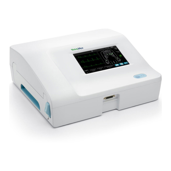
Welch Allyn CP 150 Service Manual
12-lead resting electrocardiograph
Hide thumbs
Also See for CP 150:
- Directions for use manual (88 pages) ,
- Quick reference manual (14 pages) ,
- Assembly instructions manual (8 pages)
Table of Contents
Advertisement
Quick Links
Advertisement
Table of Contents

Related Manuals for Welch Allyn CP 150


Summary of Contents for Welch Allyn CP 150
- Page 1 CP 150 12-lead resting electrocardiograph Service manual Software version 2.10.XX...
- Page 2 © 2018 Welch Allyn, Inc. All rights are reserved. To support the intended use of the product described in this publication, the purchaser of the product is permitted to copy this publication, for internal distribution only, from the media provided by Welch Allyn. No other use, reproduction, or distribution of this publication, or any part of it, is permitted without written permission from Welch Allyn.
-
Page 3: Table Of Contents
Welch Allyn Service Tool ................44 Configure your network policy certificate through the Welch Allyn Service Tool ........................46 (Optional) Upgrade your CP 150 software using a USB flash drive ....48 Perform the full-functional tests ................ 50 Electrical safety testing ..................58... - Page 4 Symptoms and solutions ................... 62 Printer ........................ 64 User interface ....................65 Post test error messages ................... 66 CP 150 spirometry option symptoms and solutions .......... 67 Guidance and manufacturer’s declarations ........69 EMC compliance ....................69 Emissions and immunity information ..............69 Disassembly, repair, and reassembly ..........
-
Page 5: Symbols
Meets essential requirements of the of the DFU is available on this website. A European Medical Device Directive printed copy of the DFU can be ordered 93/42/EC from Welch Allyn for delivery within 7 calendar days. Power symbols Power on/standby Battery... - Page 6 2 Symbols CP 150 12-lead resting electrocardiograph Fuse Rechargeable battery Protective Earth (PE) Non-ionizing electromagnetic radiation Equipotential Ground Rated power input, AC Connectivity symbols Ethernet Wireless radio symbols Wireless signal strength Non-ionizing electromagnetic radiation • Best (4 bars) • Good (3 bars) •...
- Page 7 Service manual Symbols 3 Separate collection of batteries. Do not Recyclable dispose as unsorted municipal waste. Separate collection of Electrical and China RoHs Electronic Equipment. Do not dispose as unsorted municipal waste. Lithium ion battery Keep away from sunlight IP20 Protected against the ingress of solid Use by Date foreign objects ≥...
- Page 8 4 Symbols CP 150 12-lead resting electrocardiograph...
-
Page 9: Safety
Always follow the manufacturer’s directions for use. • Welch Allyn recommends that only Welch Allyn service personnel or an authorized repair center perform warranty service. Performing unauthorized service on a device that is within warranty may void the warranty. - Page 10 6 Safety CP 150 12-lead resting electrocardiograph bags and you are not sure whether they are static-sensitive, assume that they are static- sensitive and handle them accordingly. • Perform all service procedures in a static-protected environment. Always use techniques and equipment designed to protect personnel and equipment from electrostatic discharge.
-
Page 11: General Warnings
WARNING Use only parts and accessories, including thermal paper, that were supplied with the device and available through Welch Allyn. The use of accessories other than those specified may result in degraded performance or unsafe use of this device. - Page 12 WARNING To provide CF protection use only accessories approved by Welch Allyn. Visit www.welchallyn.com. The use of any other accessories can result in inaccurate patient data, can damage the equipment, and can void your product warranty.
-
Page 13: General Cautions
Service manual Safety 9 WARNING To avoid the risk of associating reports with the wrong patients, make sure that each test identifies the patient. Do not save a test to the patient record without patient identification associated with the report. General cautions Cautions indicate conditions or practices that could damage the equipment or other property. - Page 14 10 Safety CP 150 12-lead resting electrocardiograph CAUTION The requirements of AAMI EC11, Section 3.2.7.2, Frequency and Impulse Response, for an impulse triangle waveform may be impacted by up to 5 milliseconds of small amplitude dampened ringing immediately after the impulse when the muscle filter (35 Hz) is turned on or a small amplitude offset when the baseline filter (0.5 Hz) is turned on.
-
Page 15: Overview
CAUTION No component-level repair of circuit boards and subassemblies is supported. Use only the repair procedures described in this manual. Find instructions for functional testing and performance verification in the Welch Allyn Service Tool help files. This manual applies only to this device. For servicing of any other device, see the service manual for the specific device. -
Page 16: Service Loaners
Partners in Care service agreements While product warranties provide basic assurance of Welch Allyn hardware quality, they may not include the full range of services and support you need. Welch Allyn offers premium service and support through our Partners in Care program. Whether you service your own devices and require a minimum of support or rely on us to service your device, Welch Allyn provides a program that will meet your needs. -
Page 17: Repairs
Qualified service personnel or a Welch Allyn Service Center should repair products out of warranty. If you are advised to return a product to Welch Allyn for repair or routine maintenance, schedule the repair with the service center nearest you. - Page 18 14 Overview CP 150 12-lead resting electrocardiograph Model Additional Options Accessories Language Power cord NL - Dutch G - Argentina NO - Norwegian N - India/UAE PT - Portuguese Y - Italy RU - Russian Z - Brazil SV - Swedish...
-
Page 19: The Welch Allyn Service Tool
• Install updates. The service tool can read the firmware version of the CP 150 and check for available updates or upgrades. • Install upgrades. An interpretation option is available for purchase. The CP 150 basic can be upgraded to a CP 150A (with the Interpretation option) through the Welch Allyn Service Tool. - Page 20 Welch Allyn does not accept returned products without an RMA. 2. Ship the device to Welch Allyn, observing these packing guidelines: a. Remove from the package the battery, all hoses, connectors, cables, sensors, power cords, and other ancillary products and equipment, except those items that might be associated with the problem.
- Page 21 Put the device, enclosed in a plastic bag with a packing list, into the original shipping carton with the original packing materials or into another appropriate shipping carton. d. Write the Welch Allyn RMA number with the Welch Allyn address on the outside of the shipping carton.
- Page 22 18 Overview CP 150 12-lead resting electrocardiograph...
-
Page 23: Controls, Indicators, And Connectors
Controls, indicators, and connectors No. Feature Description LCD screen 800 x 480 pixels color touchscreen provides a graphical user interface. Power switch and LED Power-on/Standby switch. The LED indicates the charging status when connected to AC power: • Green: The battery is charged. •... - Page 24 20 Controls, indicators, and connectors CP 150 12-lead resting electrocardiograph Back view No. Feature Description Ethernet connector Provides a hardwired connection to the computer network. The LEDs indicate active network status when the ethernet cable is connected to a network.
- Page 25 Service manual Controls, indicators, and connectors 21 Spirometry option back view No. Feature Description Bracket Spirometer sensor mounting bracket Thumb screws Thumb screws to attach bracket to device USB cable Provides spirometer sensor connection to device Spirometer sensor USB spirometer sensor Disposable flow transducers Measures patient air velocity.
- Page 26 22 Controls, indicators, and connectors CP 150 12-lead resting electrocardiograph...
-
Page 27: Home Screen
Home screen Home screen The Home screen includes the following areas:... - Page 28 24 Home screen CP 150 12-lead resting electrocardiograph Item Area Device status Content Navigation Device status area The Device status area, located at the top of the Home screen, displays: • Patient Icon and Patient name. Once the patient context is established, the format of the Patient name appears as last name, first name.
- Page 29 Service manual Home screen 25 Navigation area The ECG Navigation area includes the following tabs: • ECG home: Displays ECG test types and provides shortcuts to several controls. • Manage worklist : Includes patient data and orders downloaded when connected to a hospital information system (Worklist server).
- Page 30 26 Home screen CP 150 12-lead resting electrocardiograph...
-
Page 31: Settings
Settings View or change the device information To view or change the device information 1. Touch the Settings tab. The ECG tab appears. 2. Touch the Device tab. Modify the settings as desired: • LCD brightness • Date • Time •... - Page 32 28 Settings CP 150 12-lead resting electrocardiograph Regional Specify regional settings 1. Access the Advanced Settings. a. Touch the Settings tab. b. Touch the Advanced tab. c. Enter 6345 as the Advanced settings code. d. Touch OK. The General tab appears at the bottom of the screen and the Regional tab appears at the top of the screen.
- Page 33 Service manual Settings 29 Internal and PDF to USB ○ Internal and PDF to remote file location ○ • From the Default patient entry drop-down menu, select New Patient or Worklist. • Select or deselect the HR beep on. • Select or deselect the Error beep on.
- Page 34 30 Settings CP 150 12-lead resting electrocardiograph a. Touch the Settings tab. b. Touch the Advanced tab. c. Enter 6345 as the Advanced settings code. d. Touch OK. The General tab appears on the bottom of the screen and the Regional tab appears on the top of the screen.
- Page 35 To exit the Advanced Settings and return to the Home screen, touch Exit. Specify Ethernet settings You can connect a CP150 electrocardiograph to a Welch Allyn CardioPerfect workstation or a network server via an Ethernet cable. Software provided in the CP 50/150 connectivity kit is required to communicate with the workstation.
- Page 36 32 Settings CP 150 12-lead resting electrocardiograph 4. Specify settings. Setting Action/Description DHCP Select or deselect DHCP. Select DCHP to auto-connect through Ethernet. Deselect DHCP to manfully enter settings. Network IP address Touch and enter the IP address to manually set up the device for Ethernet communications.
- Page 37 1. In Advanced settings, touch the Network > Radio > Security tabs. 2. Select the encryption method to secure data transfer from the device. Note Network server certificates are required for all EAP security options. Use the Welch Allyn Service Tool to load these certificates. 3. Specify Security settings. Setting...
- Page 38 34 Settings CP 150 12-lead resting electrocardiograph Roaming PMK, OKC, CCKM Update radio Update radio Touch to activate all new radio settings not selected previously. Touch in the confirmation popup. Note None of the changed radio settings take effect until you touch Update radio.
- Page 39 Service manual Settings 35 b. Touch the Advanced tab. c. Enter 6345 as the Advanced settings code. d. Touch OK. The General tab appears at the bottom of the screen and the Regional tab appears at the top of the screen. 2.
- Page 40 36 Settings CP 150 12-lead resting electrocardiograph 4. Touch the DICOM tab to specify the DICOM settings. Setting Action/Description Enable worklist downloads and ECG DICOM uploads Select this option to enable DICOM functionality. Local AE Title Touch and enter the AE Title for the device (Example: CP150).
- Page 41 Service manual Settings 37 Test Connection Test Connection Touch to test the connection to the DICOM Image Server. 8. Do one of the following: • To continue in the Advanced Settings, touch another tab. • To exit the Advanced Settings and return to the Home screen, touch Exit.
- Page 42 38 Settings CP 150 12-lead resting electrocardiograph...
-
Page 43: Service
Service The Service tab presents numerous settings and controls typically accessed by authorized service or biomedical engineering personnel to configure, maintain, test, and update the device. For example, the Service tab enables authorized users to save device configurations to a USB flash drive and then load saved configurations to other devices. Systems and devices configured with the PartnerConnect™... -
Page 44: Upgrade Your Existing Cp 150 Device Software Version Through The Welch Allyn Service Tool
2. Follow the instructions to set up a user name and password. 3. Plug your CP 150 device into a USB port on your PC running the Welch Allyn Service Tool and turn on the device. Plug your CP 150 device into AC power. -
Page 45: Activate The Dicom License Through The Welch Allyn Service Tool
10. Click Upgrade all. Optional, click Read release notes to view upgrade details. 11. At the Upgrade Host Controller screen, click Yes at the prompt: Do you want to continue? CAUTION Do not power off the CP 150 device during the update. Note The upgrade process may take up to fifteen minutes to cycle through the complete upgrade. - Page 46 CP 150 12-lead resting electrocardiograph 1. Download the Welch Allyn Service Tool and Partner Connect and install on your PC. 2. Plug your CP 150 device into a USB port on your PC running the Welch Allyn Service Tool and turn on the device.
-
Page 47: (Optional) Upgrade Your Existing Cp 150 Device To Dicom Through The Welch Allyn Service Tool Administration Menu
1. Download the Service Tool Partner Connect and install on your PC. 2. Follow the instructions to set up a user name and password. 3. Plug your CP 150 device into a USB port on your PC running the Service Tool and turn on the device. -
Page 48: Upgrade Your Existing Cp 150 Device Wireless Radio Software Version Through The Welch Allyn Service Tool
A USB cable is required to perform the wireless radio software upgrade. 1. Download the Welch Allyn Service Tool and Partner Connect and install on your PC. 2. Plug your CP 150 device into a USB port on your PC running the Welch Allyn Service Tool and turn on the device. - Page 49 Service manual Service 45 7. Click the Upgrade tab and then click Check for new upgrades. CAUTION Do not disconnect or power off the device during the license installation. 8. Highlight the device software (for example, the firmware WelchAllyn 802.11 a/b/g/n Radio 1.XX.XX) to choose it from the list.
-
Page 50: Configure Your Network Policy Certificate Through The Welch Allyn Service Tool
A USB cable is required to perform the network policy configuration. 1. Download the Welch Allyn Service Tool and Partner Connect and install on your PC. 2. Plug your CP 150 device into a USB port on your PC running the Welch Allyn Service Tool and turn on the device. - Page 51 Service manual Service 47 7. Click the Configure tab and then click Change. 8. Browse to your certificate folder and enter your Network Policy Certificate Password.
-
Page 52: (Optional) Upgrade Your Cp 150 Software Using A Usb Flash Drive
(Optional) Upgrade your CP 150 software using a USB flash drive Before you begin updating your CP 150, verify your current software version: 1. Touch the Settings tab. 2. Touch the Advanced tab. The software version appears on the Advanced Tab screen. - Page 53 • Touch the Settings tab. • Touch the Advanced tab. The software version appears on the Advanced Tab screen • Verify that the correct software version is listed for the CP 150. You are ready to use the updated software.
-
Page 54: Perform The Full-Functional Tests
50 Service CP 150 12-lead resting electrocardiograph Perform the full-functional tests Complete the full-functional CP 150 tests to verify device functionality. Note The functional verification tests help to confirm the proper operation of the device and its options. The tests may also be useful as a diagnostic tool to help isolate a malfunction. - Page 55 Service manual Service 51 Battery test Note Ensure that the battery is installed and has been charged for a minimum of four hours before preforming this test. 1. If the Battery remaining field shows 70% or less, replace the battery. 2.
- Page 56 USB port on the PC. Verify that the PC is able to recognize CP150 device. 2. Touch Yes to confirm that your PC recognized the CP 150 device, or touch No if your PC did not recognized the CP 150 device.
- Page 57 Service manual Service 53 Keypad test 1. Press the button on the device to check the On/Off keypad. "Pass" is indicated with a √ (check mark) and "fail" is indicated with an X. 2. Touch (Next) to perform the next functional test.
- Page 58 54 Service CP 150 12-lead resting electrocardiograph ECG lead test 1. Connect a set of known good Patient Cables, with leads, to an ECG simulator. Note Any yellow dots on the lead-status screen indicate unattached or poorly attached leads. 2. Verify the lead connection on the screen by observing that all leads appear green.
- Page 59 Service manual Service 55 Printer pattern test 1. Touch Print to print a test page. 2. Use the specifications in the Print verification checklist table and the Printer pattern test and check point graphic to verify the correct operation of the device printer by comparing the pattern printed on the test page.
- Page 60 56 Service CP 150 12-lead resting electrocardiograph Printer pattern test and check point 3. Touch Yes if the test page printed correctly, or touch No if the test page did not print correctly. 4. Touch (Next) to perform the next functional test.
- Page 61 1. Use an Ethernet cable to connect the device to a known network and setup the CP 150 DHCP. (Refer to the CP 150 Directions For Use for setup instructions.) Under the Host address, enter the IP of a PC connected to the network. Touch the Ping test button to perform the test.
-
Page 62: Electrical Safety Testing
EN/IEC 62353 - Medical Electrical Equipment - Recurrent Test and Test After Repair of Medical Electrical Equipment. Due to the variability of test equipment in the field, Welch Allyn does not include specific instructions to perform electrical safety tests. When performing electrical safety tests, refer to your test equipment manuals for detailed instruction. -
Page 63: Manage Tests And Other Files
Service manual Service 59 Manage tests and other files Hardware components: Button Feature CP 150 Tests the hardware components Calibrate Resets the touch screen calibration Tests: Button Feature Tests + Print Prints the patient list from the internal memory of the CP... -
Page 64: Restore Factory Defaults And Export Or Import Of The Device Configurations
Configure from USB Loads the device configuration from USB flash drive. Print all settings Prints a list of all current CP 150 device settings to the device printer. Update Updates the device software from a USB flash drive. To begin the export or import process, insert a USB flash drive into one of the USB ports on the back of the CP150 device. -
Page 65: Troubleshooting
AC power and call Welch Allyn Technical Support immediately. CAUTION Replace parts, components, or accessories only with parts supplied or approved by Welch Allyn. The use of any other parts can lead to inferior performance and will void the product warranty. -
Page 66: Symptoms And Solutions
62 Troubleshooting CP 150 12-lead resting electrocardiograph Symptoms and solutions System problems: Symptom Possible cause Suggested action The electrocardiograph does not power There is no AC power Check the AC fuses. up when it is plugged into AC power and the AC power LED is not lit AC fuse is blown Check the AC fuses. - Page 67 Service manual Troubleshooting 63 Symptom Possible cause Suggested action Note: The electrocardiograph will go through some diagnostic tests that will cause it to take longer than usual to power up. Off-colored display Loose or faulty flex SMCE-LCD Reseat the flex SMCE-LCD at the SMCE or replace the flex SMCE-LCD.
-
Page 68: Printer
Check to ensure that the printer door is fully closed. Check the orientation of the paper. The wrong type of paper is being used Use only Welch Allyn approved paper. The electrocardiograph shuts down The battery is low or faulty Recharge or replace the battery. -
Page 69: User Interface
Service manual Troubleshooting 65 Symptom Possible cause Suggested action Presence of a foreign object in the Clean and remove foreign object from teeth of the gear the gear assembly. User interface User interface problems: Symptom Possible cause Suggested action Battery is critically low. Shutting Device automatically shuts down when it reaches If you are unable to charge the down... -
Page 70: Post Test Error Messages
66 Troubleshooting CP 150 12-lead resting electrocardiograph Symptom Possible cause Suggested action when high-speed printing has not taken place. The read-back file is corrupted. During the Service USB Host test, the content Ensure that the thumb drive and read back from file does not match the content port are working properly. -
Page 71: Cp 150 Spirometry Option Symptoms And Solutions
Service manual Troubleshooting 67 CP 150 spirometry option symptoms and solutions Problem-solving suggestions: If you try these suggestions and still have problems, contact Welch Allyn. Note Your model might not contain this feature. Symptom Possible cause Suggested action Unable to calibrate... - Page 72 68 Troubleshooting CP 150 12-lead resting electrocardiograph Symptom Possible cause Suggested action Values are too high (consistently) Pressure connection is partially Remove any foreign substance from the obstructed flow transducer or pressure tubing. Predictive values are blank The selected norm does not support...
-
Page 73: Guidance And Manufacturer's Declarations
This device complies with IEC EN 60601-1-2:2015. • All medical electrical equipment must be installed and put into service in accordance with the EMC information provided in this document and the Welch Allyn CP150 Electrocardiograph Directions for Use. •... - Page 74 70 Guidance and manufacturer’s declarations CP 150 12-lead resting electrocardiograph...
-
Page 75: Disassembly, Repair, And Reassembly
Disassembly, repair, and reassembly These procedures provide instructions for system disassembly and board removal. Except where otherwise noted, the assembly procedure is the reverse of the disassembly procedure. Each procedure may include the following: • Reassembly notes: This contains information specific to reassembly not addressed in the disassembly instructions. -
Page 76: Required Tools And Equipment
72 Disassembly, repair, and reassembly CP 150 12-lead resting electrocardiograph CP 150 Disassembly Flow chart Required tools and equipment • #1 Phillips bit • #2 Phillips bit • #10 Torx bit • 3/16" Hex Socket • 1/4" Hex Socket •... - Page 77 Service manual Disassembly, repair, and reassembly 73 The torque specifications are only applicable for the assembly processes. Note Tools and torque value used during reassembly of Main Unit: Part Number Description Torque Bit/Socket Type Specification 713017 5 in-lb ±0.5 in-lb Shoulder Screw, EAR G-411-1 Metric 106124-34 5 in-lb ±0.5 in-lb...
-
Page 78: Power Down The Electrocardiograph
74 Disassembly, repair, and reassembly CP 150 12-lead resting electrocardiograph Power down the electrocardiograph 1. Press and hold the button for 6-8 seconds to shut down the electrocardiograph. 2. Remove the power supply. Remove the battery... -
Page 79: Separate The Top Housing Assembly From The Bottom Housing Assembly
Service manual Disassembly, repair, and reassembly 75 Separate the top housing assembly from the bottom housing assembly 1. Turn the electrocardiograph over to access the bottom housing assembly. 2. Remove the eight M4x10 screws from the bottom housing assembly using a #2 Phillips bit. - Page 80 76 Disassembly, repair, and reassembly CP 150 12-lead resting electrocardiograph 9. Unhook the wireless radio USB cable from the LCD frame catch. 10. Disconnect the wireless radio USB cable at CN503 from the Input/Output (I/O) communication board. Note Your model might not contain this feature. Steps 9 and 10 only apply to models with a wireless radio.
- Page 81 Service manual Disassembly, repair, and reassembly 77 Cable identification for reassembly:...
- Page 82 78 Disassembly, repair, and reassembly CP 150 12-lead resting electrocardiograph Top housing disassembly These procedures provide instructions for system disassembly and board removal. Except where otherwise noted, the assembly procedure is the reverse of the disassembly procedure. Remove the Input/Output (I/O) communication board •...
- Page 83 Service manual Disassembly, repair, and reassembly 79 2. Disconnect the J7 and J15 connectors from the SMCE board. 3. Disconnect the WA7 connector from the display assembly. 4. Remove the four 4-20 self-tapping screws from the I/O board using a #1 Phillips bit.
- Page 84 80 Disassembly, repair, and reassembly CP 150 12-lead resting electrocardiograph 5. Disconnect the three harness cables at CN202, CN203, and CN201 from the I/O board and remove the harnesses. Note Set the harness cables aside for reuse during reassembly. Reassembly note •...
- Page 85 Service manual Disassembly, repair, and reassembly 81 Remove the SMCE board • Separate the top housing assembly from the bottom housing assembly as described. 1. Lift up the latch of the J18 connector on the SMCE board and disconnect the flex cable.
- Page 86 82 Disassembly, repair, and reassembly CP 150 12-lead resting electrocardiograph 3. Remove the four M3x5 screws from the SMCE board using a #1 Phillips bit. Reassembly note • Use a #1 Phillips bit and a Torque driver calibrated to 5.0 in-lb ± 0.5 in-lb to secure the SMCE board M3x5 screws.
- Page 87 Service manual Disassembly, repair, and reassembly 83 3. Remove the interface board. Reassembly notes • Use a #1 Philips bit and a Torque driver calibrated to 5 in-lb ±0.5 in-lb to secure the interface board to the LCD frame.
- Page 88 84 Disassembly, repair, and reassembly CP 150 12-lead resting electrocardiograph Remove the LCD frame and display assembly • Separate the top housing assembly from the bottom housing assembly as described. 1. Remove the Pro-Gaff tape that holds the power switch flex cable to the LCD frame and the top housing assembly.
- Page 89 Service manual Disassembly, repair, and reassembly 85 Reassembly notes • Use a #2 Phillips bit and a Torque driver calibrated to 5.0 in-lb ± 0.5 in-lb to secure the LCD frame shoulder screws. Ensure that the LCD flex cable is not under the LCD frame. CAUTION The LCD flex cable is extremely fragile and easily damaged.
- Page 90 86 Disassembly, repair, and reassembly CP 150 12-lead resting electrocardiograph Bottom housing disassembly These procedures provide instructions for system disassembly and board removal. Except where otherwise noted, the assembly procedure is the reverse of the disassembly procedure. Remove the wireless radio •...
- Page 91 Service manual Disassembly, repair, and reassembly 87 4. Disconnect the WiFi radio USB cable connector from the WiFi radio holder. Reassembly notes • Use a #2 Phillips bit and a Torque driver calibrated to 5.0 in-lb ± 0.5 in-lb to secure the two M4 pan head screws to the WiFi radio holder.
- Page 92 88 Disassembly, repair, and reassembly CP 150 12-lead resting electrocardiograph 3. Remove the two M3x5 screws from the ECG board using a #1 Phillips bit. 4. Push back slightly on the two latches to remove the ECG board from the bottom assembly.
- Page 93 Service manual Disassembly, repair, and reassembly 89 Remove the battery housing cover and the battery connector board • Separate the top housing assembly from the bottom housing assembly as described. 1. Disconnect the CN304 connector from the printer board. 2. Remove the four M4 pan head screws from the battery housing top cover using a #2 Phillips bit.
- Page 94 90 Disassembly, repair, and reassembly CP 150 12-lead resting electrocardiograph 4. Disconnect the J3 and J2 connectors from the battery connector board to remove the cables.
- Page 95 Service manual Disassembly, repair, and reassembly 91 5. Remove the two 4-20 self-tapping screws from the battery connector board using a #1 Phillips bit. Reassembly notes • Use a #1 Phillips bit and a Torque driver calibrated to 5.0 in-lb ± 0.5 in-lb to secure the two 4-20 self-tapping screws to the battery connector board.
- Page 96 92 Disassembly, repair, and reassembly CP 150 12-lead resting electrocardiograph Remove the power supply assembly • Separate the top housing assembly from the bottom housing assembly as described. 1. Remove the P1 and J1 connectors from the power supply assembly.
- Page 97 Service manual Disassembly, repair, and reassembly 93 Remove and disassemble the printer assembly • Separate the top housing assembly from the bottom housing assembly as described. 1. Remove the ground cable at the J603 connection from the printer board (PCA). 2.
- Page 98 94 Disassembly, repair, and reassembly CP 150 12-lead resting electrocardiograph Ground cable routing for reassembly:...
- Page 99 Service manual Disassembly, repair, and reassembly 95 Remove the printer board • Separate the top housing assembly from the bottom housing assembly as described. Note Service the printer board as part of the complete printer assembly. The printer board is not available as a single component. These removal procedures provide instructions for system disassembly and board removal.
- Page 100 96 Disassembly, repair, and reassembly CP 150 12-lead resting electrocardiograph 3. Remove the printer board by lifting up the side nearest the print roller and sliding it out from the printer board catch. 4. Separate the printer tray assembly from the printer top assembly by pressing the tray eject button and sliding out the paper tray assembly.
- Page 101 Service manual Disassembly, repair, and reassembly 97 • Use a #10 Torx bit and a Torque driver calibrated to 5.0 in-lb ± 0.5 in-lb to secure the 4-20 pan head screw to the printer top assembly.
- Page 102 98 Disassembly, repair, and reassembly CP 150 12-lead resting electrocardiograph Printer disassembly These procedures provide instructions for system disassembly and board removal. Except where otherwise noted, the assembly procedure is the reverse of the disassembly procedure. Remove the gear train and motor •...
- Page 103 Service manual Disassembly, repair, and reassembly 99 2. Remove the three 4-20 screws from the printer tray using a #1 Phillips bit. 3. Remove the two M3x6 screws from the gear train assembly using a #1 Phillips bit. Reassembly notes •...
- Page 104 100 Disassembly, repair, and reassembly CP 150 12-lead resting electrocardiograph Remove the print head assembly • Separate the top housing assembly from the bottom housing assembly as described. 1. Feed the 3 printer harnesses through the openings of the printer top housing.
- Page 105 Service manual Disassembly, repair, and reassembly 101 4. Slide the print head assembly inward and then upward through the retaining channel.
- Page 106 102 Disassembly, repair, and reassembly CP 150 12-lead resting electrocardiograph Remove the Cue sensor board and the print head 1. Remove the two M3x0.5 screws from the Cue sensor board with a #1 Phillips bit. 2. Remove the nut with ¼” Hex Socket to remove the ground harness.
- Page 107 Service manual Disassembly, repair, and reassembly 103 3. Remove the two shoulder screws with a 3/16" Hex Socket. 4. Remove the two connectors on each side of the print head to remove the print head harness. Reassembly notes • Use a #1 Phillips bit and a Torque driver calibrated to 5.0 in-lb ± 0.5 in-lb to secure the Cue sensor board M3x0.5 screws.
- Page 108 104 Disassembly, repair, and reassembly CP 150 12-lead resting electrocardiograph 2. Insert the spirometer sensor into the mounting bracket. Ensure that the spirometer sensor label is visible in the mounting bracket window so that the mini USB cable connector installs correctly during the next steps.
- Page 109 CAUTION Hand-tighten the spirometer sensor and flow transducer connectors to avoid damaging the connectors. The CP 150 software automatically activates the spirometry functions throughout the software. Once the software recognizes the sensor, the Spirometry button appears in the Content area.
- Page 110 106 Disassembly, repair, and reassembly CP 150 12-lead resting electrocardiograph...
-
Page 111: Field Replaceable Units
Field replaceable units This listing includes only field-replaceable service parts. Note Product accessories are listed separately in the CP 150 12-lead resting electrocardiograph Directions for use and the CP 150 spirometry option Directions for use. While the service kits are shown with the contents listed underneath each... - Page 112 108 Field replaceable units CP 150 12-lead resting electrocardiograph Item CP150 Subassembly Housing top 1 ea CP150 Power Switch 1 ea Product label 1 ea Wire tie holder with adhesive 1 ea CP150 ESD Switch tape 1 ea Serv Kit, CP150, Switch power assembly 4ED (material no. CP150-0040)
- Page 113 Service manual Field replaceable units 109 Serv Kit, CP150, I/O PCA 4ED (material no. CP150-0048) Item CP150I/O PCA Assy 1 ea Harness SMCE-I/O 1 ea Harness I/O IF PRT 1 ea CP150 EMC Harness Ferrite 1 ea ECG Ferrite 1 ea Wire tie 1 ea Serv Kit, CP150, ESD Filter PCBA 4ED (material no.
- Page 114 110 Field replaceable units CP 150 12-lead resting electrocardiograph Serv Kit, SMCE PCA (material no. CP150-0045) Item Assy, Small Med Compute Eng (SMCE) 1 ea Harness SMCE-I/O 1 ea Harness I/O-LCD 1 ea CP150 EMC Harness Ferrite 3 ea ECG Ferrite...
- Page 115 Service manual Field replaceable units 111 Serv Kit, CP150, 7 Inch Display (material no. CP150-0002) Item LCD Assy with Touch Panel 1 ea LCD Bezel 7 inch 1 ea Flex SMCE-LCD Display 7 inch 1 ea Serv Kit, LCD bracket (material no. CP150-0041)
-
Page 116: Bottom Assembly
Wire tie holder with adhesive 2 ea Bottom assembly Srv Kit, CP150, Bottom assy W/D (material no. CP150-0036) Replacement of the bottom assembly is limited to only Welch Allyn service Note personnel or an authorized Welch Allyn repair center. Item... - Page 117 Service manual Field replaceable units 113 Item Ground poag 1 ea Bumpers 5 ea Serv Kit, Wireless radio Int W/D kit (material no. CP150-0039) Item CP150 WiFi holder assembly 1 ea M4x10 pan head screws 2 ea CP150 WiFi USB cable 2 ea Radio label 1 ea...
- Page 118 114 Field replaceable units CP 150 12-lead resting electrocardiograph Item ECG PCA Assy 1 ea CP150 Harness ECG SMCE 1 ea ECG Ferrite 1 ea Serv Kit, Battery Case Assy (material no. CP150-0007) Item Assy Battery Cover bottom 1 ea...
- Page 119 Service manual Field replaceable units 115 Serv Kit, Power supply (material no. CP150-0016) Item Power supply, 60 W 1 ea Serv Kit, Battery door (material no. CP150-0018) Item Battery door 1 ea...
- Page 120 116 Field replaceable units CP 150 12-lead resting electrocardiograph Serv Kit, Miscellaneous 4ED (material no. CP150-0047) Item Screw 4-20 pan Phillips 30 ea Screw M4X10 30 ea Shoulder screw 10 ea Pan head M3x5 10 ea Pan Phillips M3x0.5 10 ea Shoulder screw M3x0.5...
- Page 121 Service manual Field replaceable units 117 Serv Kit, SMCE - ECG harness kit 4ED (material no. CP150-0049) Item SMCE - ECG harness 1 ea ECG ferrite 1 ea Serv Kit, PSU - BAT harness (material no. CP150-0025) Item PSU - BAT - SMB - PRT - SMCE harness 1 ea Serv Kit, SMCE –...
- Page 122 118 Field replaceable units CP 150 12-lead resting electrocardiograph Item 8 inch printer assembly 1 ea Serv Kit, Power harness kit (material no. CP150-0038) Item AC PSU and GND harness 1 ea Serv Kit, Door Sensor (material no. CP150-0014) Item...
-
Page 123: Printer Assembly
Service manual Field replaceable units 119 Printer assembly Serv Kit, Gear Train Assy (material no. CP150-0012) Item Gear train assy 1 ea Serv Kit, Motor Assy (material no. CP150-0013) Item Harness motor 1 ea Wire tie 1 ea... - Page 124 120 Field replaceable units CP 150 12-lead resting electrocardiograph Serv Kit, Print Head Assy (material no. CP150-0011) Item Printhead Holder 1 ea Printhead 1 ea Printhead spring 1 ea Shoulder screws M3x0.5 2 ea Screw pan head Phillips M3 x 0.5...
- Page 125 Service manual Field replaceable units 121 Serv Kit, CP150, Tray paper assy (material no. CP150-0009) Item 1 ea Printer 8 in Assy Tray 1 ea Printer 8 in Assy top (handle) 3 ea Screw 4-20 .375 pan Phillips 1 ea Printer 8 in Platen Roller Assy...
- Page 126 122 Field replaceable units CP 150 12-lead resting electrocardiograph Serv Kit, Printer Top Assy (material no. CP150-0010) Item Housing top 1 ea Latch assy 1 ea Coil spring right 2 ea Coil spring left 1 ea Retaining ring 1 ea...
-
Page 127: Partners In Care Service And Support Agreements
CP150, extended warranty, 1 year S4-CP150-2 CP150, extended warranty, 2 years Service and support agreements are not available at all levels, in every Note market. Contact your local Welch Allyn Customer Service Center for availability. Preventive service Material no. Item... - Page 128 124 Partners in Care service and support agreements CP 150 12-lead resting electrocardiograph...
-
Page 129: Appendices
Electrocardiograph or accessories. WARNING Liquids can damage electronics inside the CP 150 Electrocardiograph. Prevent liquids from spilling on or dripping into the CP 150 Electrocardiograph. If liquids are spilled on or drip into the CP 150 Electrocardiograph: 1. Disconnect the power plug. -
Page 130: Cleaning The Spirometer, Calibration Syringe, And Patient Handle
126 Appendices CP 150 12-lead resting electrocardiograph Disinfect according to your facility's protocols and standards or local Note regulations. 70 percent isopropyl alcohol Wipe the electrocardiograph with a clean cloth slightly dampened with 70 percent isopropyl alcohol. 10 percent chlorine bleach solution 1. - Page 131 Service manual Appendices 127 • 70 percent isopropyl alcohol • 10 percent chlorine bleach solution CAUTION When cleaning the patient handle, do not use cloths or solutions that include quaternary ammonium compounds (ammonium chlorides) or glutaraldehyde-based disinfectants. Note Disinfect according to your facility's protocols and standards or local regulations.
-
Page 132: Interconnect Diagram
128 Appendices CP 150 12-lead resting electrocardiograph Interconnect diagram...
Need help?
Do you have a question about the CP 150 and is the answer not in the manual?
Questions and answers
is there a way to have the header down further on the top of the page