Table of Contents
Advertisement
Advertisement
Table of Contents

Subscribe to Our Youtube Channel
Related Manuals for Tenda G3


Summary of Contents for Tenda G3
-
Page 2: Copyright Statement
Tenda reserves the right to make changes to the products without obligation to notify any person or organization of such revisions or changes. Tenda does not assume any liability that may occur due to the use or application of the product described herein. Every effort has been made in the preparation of this document to ensure accuracy of the contents, but all statements, information and recommendations in this document do not constitute the warranty of any kind, express or implied. -
Page 3: Technical Support
Preface Preface Thank you for choosing Tenda! Please read this user guide before you start. This user guide instructs you to configure the product G3. Conventions Typographical conventions in this User Guide: Item Presentation Example 『』 The menu "Status" will be simplified as 『Status』. -
Page 4: Document Overview
Preface Document Overview The structure of the user guide is described as following: Chapter Content 1 Product Overview About router appearance, packaging, functional characteristics, etc. 2 Device Installation About router installation steps and installation notes. 3 Internet Access Setup About steps for setting Internet access parameters of the router. 4 Device Management About the router management page and the use of the functions in the page. -
Page 5: Table Of Contents
Table of Contents Table of Contents Product Overview ....................- 1 - 1.1 Overview ................................ - 2 - 1.2 Feature ................................- 2 - 1.3 Appearance ..............................- 3 - 1.4 Package Contents ............................- 5 - Device Installation ....................- 6 - 2.1 Installation Notes ............................ - Page 6 Table of Contents 4.10 Virtual Server ............................- 104 - 4.11 USB................................- 116 - 4.12 Maintenance ............................- 127 - 4.13 System status ............................- 140 - Appendix ......................- 145 - 1 Obtain IP address autimatically ........................- 146 - 2 Product Specification ............................
-
Page 7: Product Overview
Product Overview Overview Main Features Appearance Package Contents... -
Page 8: Overview
VPN, a maximum of 15 concurrent tunnels. In addition, provide the AC management function to manage all models of APs of Tenda. G3 provides a 200-people standard device quantity and can manage up to 16 APs. Meet the requirements of enterprises and hotels for establishing an efficient, safe and manageable network. -
Page 9: Appearance
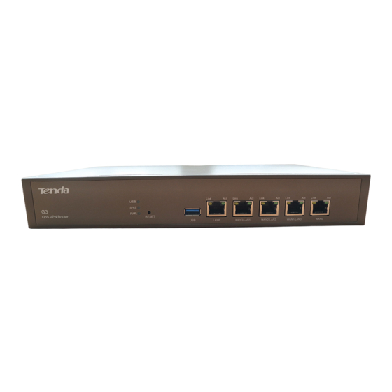
Product Overview 1.3 Appearance 1.3.1 Front Panel After the device is energized, the indicator states are described as follows: Indicators Color Description Solid indicates normal power-on. Green Off indicates abnormal power-on. Please check whether the power cord is loose. Solid indicates that a USB device is connected. Green Blinking indicates that a USB device and this USB port have data transmission. -
Page 10: Rear Panel
Product Overview Port and Button Description In power-on state, press and hold the button with a spike for 8s and release it, and the RESET device will be restored to factory state. USB3.0 Connects USB devices such as USB disks, mobile hard disks, and printers. LAN0 Intranet port that connects devices such as switches and computers. -
Page 11: Package Contents
Product Overview 1.3.3 Label at the Bottom (1): The login IP address for router. This IP address can be used to go to the web login page of this router. (2): Default login user name and password, it can be used to go to the web login page of this router. 1.4 Package Contents Unpack the package. -
Page 12: Device Installation
Device Installation Installation Notes Installing the Router Connecting the Router - 6 -... -
Page 13: Installation Notes
Device Installation 2.1 Installation Notes Follow the following notes to avoid device damage or personal injury due to improper use. 2.1.1 Safety Measures It is necessary to wear antistatic gloves in the installation process and the device must not be powered on. ... -
Page 14: Installing The Router
Device Installation Anti-lightning requirement To avoid any damage to the device due to strong transient current generated from thunder and lightning, take the following lightning protection measures: Confirm that the power socket, rack, and worktable contact the ground well. The cabling shall be reasonable to avoid inducing lightning internally. -
Page 15: Connecting The Router
Device Installation Step 3: Fix the device on the rack with screws (provided by the user). 2.2.2 Tabletop Installation If the user does not have a 19-inch standard cabinet, the tabletop installation mode can be used. Step 1: Place the device on the tabletop with the bottom upward and paste 4 foot pads into the round groove at the bottom of the shell. - Page 16 Device Installation Step 2: Connect switches and other network devices (such as APs, servers, and computers) with network cables. After checking that the network topological graph is correct, connect the router to the power socket with the power cord in the product packaging box and press the power switch to power on the router. - 10 -...
-
Page 17: Internet Access Setup
Internet Access Setup Step 1: Log in to the router management page Step 2: Set Internet access parameters - 11 -... -
Page 18: Step 1: Log In To The Router Management Page
Internet Access Setup Step 1: Log in to the router management page Step 1: Set the local connection of the computer to obtain an IP address automatically and Obtain DNS server address automatically. For detailed steps, refer to 1 Configure your computer. -
Page 19: Step 2: Set Internet Access Parameters
Internet Access Setup Step 2: Set Internet access parameters Set Internet access information. Select one connection method from Methods 1, 2, and 3 according to actual situations. Try to surf the Internet after settings are finished. Click 『Network』 to go to the Internet Setup page. ... - Page 20 Internet Access Setup Method 1: There is a broadband user name and password provided by operators such as China Telecom and China Unicom. The connection method is ADSL. Perform settings by referring to the figure below. Configuration steps: ❶ Connection Type: Click to select ADSL. ❷...
- Page 21 Internet Access Setup Method 2: For users whose computers need only to be connected with a broadband network cable for Internet access when the router is not used, the connection method is Dynamic IP. Perform settings by referring to the figure below.
- Page 22 Internet Access Setup Method 3: For users who have fixed IP addresses provided by operators for Internet access, the connection method is Static IP. Perform settings by referring to the figure below. Configuration steps: ❶ Connection Type: Click to select Static IP. ❷...
-
Page 23: Device Management
Device Management Device Management Overview of Page Network Filter Management Bandwidth Control Security AC Management Captive Portal PPPoE Authentication Virtual Server - 17 -... - Page 24 Device Management Maintenance System - 18 -...
-
Page 25: Overview Of Page
Device Management 4.1 Overview of Page Go to the management page of the router. The web management page is divided into three parts: primary navigation bar, secondary navigation bar and configuration area, described as follows. Name Description The navigation bar organizes the router's menu of all functions in the form of a Primary ❶... -
Page 26: Network
Device Management 4.2 Network Network includes the following contents: Internet Setup: Set router Internet access information. Parameters: Modify WAN port parameters including WAN Speed, MTU, and MAC Address. Setup: Modify relevant parameters of LAN IP and DHCP server. Port Mirroring: Set the router port mirroring function. Static Route: View router route forwarding information and configure static routing. - Page 27 Device Management Parameter description in the page: Parameter Description Set the number of WAN ports and view RJ45 port status (connection status. The role is WAN or LAN port). The device enables 2 WAN ports by default. After the number of WAN ports is modified, the RJ45 port status diagram will also be changed as follows: WAN ports indicates that the port connection is normal.
-
Page 28: Wan Parameters
Device Management Parameter Description Handle the size of bandwidth. Consult a corresponding broadband operator. Note Line Bandwidth If this item is empty, it will affect the "Intelligent Bandwidth Control" and "Smart Load Balancing" functions. Please fill in it. Display the connection status of a WAN port. The states mainly include: ... -
Page 29: Lan Setup
Device Management Please use a correct MAC address to perform the clone action! A correct MAC address is a MAC address of a computer on which a technician performs commissioning to surf the Internet during broadband installation. Parameter description in the page: Parameter Description WAN Speed... -
Page 30: Port Mirroring
Device Management Configuration steps for modifying a LAN port IP address: ❶ LAN IP: Modify an IP address such as 192.168.10.1. ❷ Click OK. After clicking OK, wait a moment. After the progress bar is over, if login fails, ensure that the method for obtaining a computer IP address is Obtain an IP address automatically. - Page 31 Example of port mirroring Example: An enterprise purchases a G3 enterprise router to establish a network. Recently, the network in the company is abnormal so that Internet access often fails. The port mirroring function can be used to capture WAN and LAN port data for analysis.
-
Page 32: Static Route
Device Management The reference application scenario is as follows: Configuration steps: ❶ Port Mirroring: Click Enable. ❷ Mirrored port: Click to select monitored ports such as LAN1, LAN2, WAN1, and WAN0. ❸ Click OK. After settings are finished, the computer installed with monitoring software (connected to the LAN0 port of the router) can monitor packets of other ports. - Page 33 Example of static route Example: An enterprise purchases a G3 enterprise router to establish a network. The Intranet and Internet are located in different networks. The router has been connected to the Internet through the WAN0 port and to the Intranet through the WAN1 port. Now, it must be realized that the client under the router needs to access both the Internet and Intranet.
- Page 34 Device Management Internet access information assigned by the company: Username tenda Password tenda Intranet server information is as follows: IP Address 172.16.0.0 Subnet mask 255.255.0.0 The reference topological graph is as follows: Configuration steps: Step 1: Set a WAN port according to information assigned by the company (The Internet is connected to the WAN0 port.
- Page 35 Device Management - 29 -...
- Page 36 Device Management Step 2: Set static router rules. ❶ Click ❷ Set static router rules. Destination Network/ Subnet Mask: Enter a destination network address and subnet mask. Gateway: Enter a gateway address to the Intranet. Interface: Select a router port that a destination network is connected to. ...
- Page 37 To realize Internet access by plugging a network cable by customers, Tenda develops the hotel mode function. After this function is enabled, customers can surf the Internet by plugging a network cable regardless of IP address settings of customers' computer network cards, thus being convenient and simple.
-
Page 38: Filter Management
Device Management 4.3 Filter Management Filter Management includes the following contents: IP Group & Time Group: Set an IP group and time group. Applications such as Port Filter, Web Filter, and Multi-WAN Policy will be used. Filter: Set limitations on a specified client from surfing the Internet. Port Filter:Set limitations on a client from accessing a specified port. - Page 39 Device Management Steps for Adding a Time Group Click Set time group rule contents in the window that appears. ❶ Set a name for this rule. ❷ Set specific time. ❸ Click OK to finish settings. Steps for adding an IP group Click Set IP group rule contents in the window that appears.
-
Page 40: Mac Filter
Device Management 4.3.2 MAC Filter Overview Computers and laptops that people often use have respective MAC addresses. You can control LAN clients' access to the Internet through the MAC Filter function. MAC Filter has two access control modes: Allow_Internet and Forbid_Internet. - Page 41 Device Management Parameter description in the page: Parameter Description MAC Filter Enable/Disable the MAC filter function. The default is Disable. Click this button to add a MAC filter rule. Click this button to delete a selected rule. White List: Allow a device with this MAC address to access the Internet. Mode ...
- Page 42 Example of MAC filter Example: An enterprise uses a G3 enterprise router to establish a network. The staffs are forbidden from surfing the Internet in office hours, but recruiters are allowed to do so in office hours (8:00 - 18:00). This can be achieved through the MAC filter function.
- Page 43 Device Management Step 3: Set MAC Filter rule contents. Click Set rule contents in the window that appears. ❶ Click to select Allow access to the Internet. Click the dropdown list to ❷ select a corresponding time group. ❸ Enter corresponding address information.
-
Page 44: Port Filter
Device Management 4.3.3 Port Filter Overview Network protocols involved by many services in the Internet have specific port numbers.0-1023 are the port numbers of typical ports. These port numbers are generally assigned to specific services. To facilitate further management on clients in the LAN, the access of clients in the LAN to some ports in the Internet can be controlled by setting the port filter function. - Page 45 Example of port filter Example: An enterprise uses a G3 enterprise router to establish a network. Computers with IP addresses 192.168.0.2-192.168.0.100 in the LAN cannot browse a web page at 8:00-18:00 (office hours) of Monday to Friday. (The port for the service of browsing a web page is 80 by default.) Configuration steps: Step 1: Set a time group (8:00 - 18:00) as follows.
- Page 46 Device Management Step 2: Set an IP group (IP field is 192.168.0.2-192.168.0.100) as follows. For detailed configuration steps, refer to Steps for adding an IP group. Step 3: Enable the Port Filter function. Click Enable and OK. Step 4: Set Port Filter rule contents. ❶...
- Page 47 Device Management ❶ Set rule contents in the window that appears. IP Group、Time Group: Click the dropdown list and select a corresponding IP. Ports: Set a service port unaccessible for the LAN that may be a single port or port segment. ...
-
Page 48: Web Filter
Device Management 4.3.4 Web Filter Overview This describes how to set the web filter function. This router can forbid any specified client in the LAN from using any specified applications such as communication software, video software, and music software. Click 『Filter Management』>『Web Filter』 to go to the configuration page. You must define a website before performing filter settings. - Page 49 Device Management Parameter Description Web Filter Enable/Disable the web filter function. The default is Disable. Click this button to add a web filter rule. Click this button to delete a selected rule. IP Group IP group where the rule is valid. Time when the rule is valid, i.e.
- Page 50 Device Management Example of web filter Example: An enterprise uses a G3 enterprise router to establish a network. Computers with IP addresses 192.168.0.2-192.168.0.100 in the LAN cannot access yahoo.com at 8:00-18:00 (office hours) of Monday to Friday. Configuration steps: Step 1: Set a time group (8:00 - 18:00) as follows.
- Page 51 Device Management Step 3: Set the Web Filter function. Click Enable and OK to enable the Web Filter function. Add website contents to be filtered. Click - 45 -...
- Page 52 Device Management Set rule contents in the window that appears. ❶ Set a rule name. ❷ Set a website to be filtered. ❸ Set website description. ❹ Click OK to finish settings. The rule addition is finished, as shown in the figure below: Set website filter.
- Page 53 Device Management Set filter rule contents. IP Group、Time Group: Click the dropdown list and select a corresponding IP group and time group. Classification: Select an application type that is forbidden from being used by a client. When adding multiple websites, you can quickly select them through and Invert.
- Page 54 Example of custom Example: An enterprise uses a G3 enterprise router to establish a network. Broadband services provided by both China Telecom and China Mobile are handled to meet enterprise network requirements. The Internet has been successfully accessed. Multi-WAN policy settings can be performed to manage the network better.
- Page 55 Device Management ❸ Click Add a new rule. ❹ IP Group: Click the dropdown list to select a corresponding IP group. ❺ WAN: Select a WAN port where the data traffic of the IP group passes. ❻ Click OK to finish settings. The rule addition is finished, as shown in the figure below: - 49 -...
-
Page 56: Bandwidth Control
Device Management 4.4 Bandwidth Control Overview This section describes how to set the router traffic function. By setting corresponding limitation rules on various data traffic, bandwidth control on data transmission can be realized so that limited bandwidth resources are reasonably allocated to achieve the objective of effectively using the existing bandwidth. Click 『Bandwidth Control』... - Page 57 Example of custom Example: An enterprise uses a G3 enterprise router to establish a network. The router LAN port IP address is 192.168.0.252. The subnet mask is 255.255.255.0. Bandwidth control on a client under the router needs to be set so that the client has a fixed bandwidth. The IP address is 192.168.0.2-192.168.0.100. The time group restricted for the broadband is 8:00-18:00.
- Page 58 Device Management Step 2: Set an IP group (IP field is 192.168.0.2-192.168.0.100) as follows. For detailed configuration steps, refer to Steps for adding an IP group. Step 3: Click Custom and OK to enable the "Custom" function. - 52 -...
- Page 59 Device Management Step 4: Set "Custom" rule contents. Click Set rule contents in the window that appears. IP Group, Time Group: Click the dropdown list and select a corresponding IP group and time group. Concurrent session: It is recommended to set this parameter to 300 in the absence of exceptional circumstances.
-
Page 60: Vpn
Device Management 4.5 VPN VPN includes the following contents: PPTP/L2TP Client: The router as a client is connected to the server. PPTP/L2TP Server: The router as a server allows a specified client to be connected to it. IPSec: Establish an IPSec tunnel to implement VPN transmission. Example of PPTP/L2TP configurations: Explain VPN application through the example of PPTP server/client. - Page 61 Device Management Click 『VPN』 to go to the PPTP/L2TP Client configuration page. After PPTP/L2TP Client is enabled, the page is shown in the figure below. - 55 -...
- Page 62 Device Management Parameter description in the page: Parameter Description Enable or disable the PPTP/L2TP client function. After this function is enabled, the PPTP/L2TP Client router is used as a VPN client. Type Type of client that the router acts as, including PPTP Client and L2TP Client. Select the current WAN port, i.e.
- Page 63 Device Management After PPTP/L2TP Server is enabled, the page is shown in the figure below. - 57 -...
- Page 64 Device Management Parameter description in the page: Parameter Description Enable/Disable the PPTP/L2TP server function. After this function is Status enabled, the router is used as a VPN server. Type of server that the router acts as, including PPTP Server and L2TP Type Server.
- Page 65 Device Management and prevents any network attack in the IP network. Click 『VPN』>『IPSec』 to go to the configuration page. After IPSec is enabled, the page is shown in the figure below. - 59 -...
- Page 66 Device Management Parameter description in the page: Parameter Description IPSec Enable/Disable the IPSec function. Router port where IPSec is enabled. The IP address of this port is "Remote Gateway Address" information of the remote router. Connection Name Set a name for this IPSec connection to facilitate identification. Select ESP, AH or AH+ESP as needed.
- Page 67 Device Management Click Hide Advanced …, and the page below appears: Parameter description in the page: Parameter Description Set an exchange mode negotiated in Stage 1. This exchange mode must be the same as that of the remote end. There are two exchange modes as follows: ...
- Page 68 Device Management using a 128/192/256-bit key. Parameter Description Select a verification algorithm applied to an IKE session. The router supports the following verification algorithms: Integrity MD5 (Message Digest Algorithm): Generate a 128-bit message digest for a message to Verification prevent this message from being falsified.
- Page 69 Device Management Parameter description in the page: Parameter Description Set an ESP encryption algorithm when selecting an ESP security protocol. The router supports the following encryption algorithms: DES (Data Encryption Standard): Encrypt64-bit data using a 56-bit key. The last 8 bits ESP Encryption of 64 bits are used for parity check.
- Page 70 4.5.4 Example of PPTP/L2TP configurations Example: The headquarters and the branch use a G3 enterprise router to establish a network with successful access to the Internet. Employees in the branch need to access the company's resources via the Internet at any time.
- Page 71 Device Management Add a username and password whose access is allowed. ❶ Click Add a user. Set a username and ❷ password used when the client is connected to the server, such as admin. Enter a client LAN and ❸ subnet mask.
- Page 72 Device Management After settings are successfully finished, the page is shown in the figure below. Step 2: Set Router 2 that acts as a client. ❶ PPTP/L2TP Client: Click Enable. ❷ Type: Click PPTP client. ❸ WAN: Select an enabled WAN port of Router 2 (VPN client) (In this example, WAN0). ❹...
- Page 73 Device Management After settings are successfully finished, the page is shown in the figure below. The connection is successful when the status is displayed as Connected and an IP address has been obtained. - 67 -...
- Page 74 4.5.5 Example of IPSec configurations Example: The headquarters and the branch use a G3 enterprise router to establish a network with successful access to the Internet. Employees in the branch need to access the company's resources via the Internet at any time.
- Page 75 Device Management Set rule contents. ❶ IPSec: Click Enable. ❷ WAN: Select an enabled WAN port of this tunnel (In this example, WAN0). ❸ Connection Name: Set a name for this tunnel such as IPSec_1. ❹ Remote Gateway (Domain Name): Enter an IP address of the enabled WAN port of the IPSec tunnel of the remote router (In this example, 210.76.200.101).
- Page 76 Device Management Set rule contents. ❶ IPSec: Click Enable. ❷ WAN: Select an enabled WAN port of this tunnel (In this example, WAN0). ❸ Connection Name: Set a name for this tunnel such as IPSec_1. ❹ Remote Gateway (Domain Name): Enter an IP address of the enabled WAN port of the IPSec tunnel of the remote router (In this example, 202.105.106.55).
- Page 77 Device Management Step 3: Verify whether settings are successful. Go to the management page of the router. Click 『System』>『Live Users』 to go to the page. When the number of connections is displayed in IPSec, settings are successful. If you want to set the advanced option of the IPSec tunnel in the setting process, keep the setting parameters of two routers consistent.
-
Page 78: Security
Device Management 4.6 Security Security includes the following contents: IP-MAC Binding: Set the function that only the users bound to IP and MAC addresses in the list can access the Internet. Firewall: Set the defense function of the device. You can set this part under the guide of a professional. 4.6.1 IP-MAC Binding Overview The IP-MAC address binding function allows users bound to IP and MAC addresses in the list to access the... - Page 79 Device Management After an "IP-MAC Binding" rule is added, the page is shown in the figure below. Parameter description in the page: Parameter Description IP-MAC Binding Enable/Disable the IP-MAC binding function. The default is Disable. Click this button to manually add bound IP and MAC addresses. Click this button to unbind a selected bound rule.
- Page 80 Example of IP-MAC binding Example: An enterprise uses a G3 enterprise router to establish a network. Only two employees in the recruitment team are allowed to access the Internet in office hours of the company. Other employees are forbidden from accessing the Internet. This can be achieved through the IP-MAC binding function. First of all, you must know the IP and MAC addresses of the recruiters who are allowed to access the Internet, i.e.
- Page 81 Device Management list and click Bind. If it is not connected to the router, click Add, enter IP and MAC address information to be bound, and click OK. After addition is successful, the page is shown in the figure below. - 75 -...
- Page 82 Device Management 4.6.2 Firewall Firewall includes ARP Attack Defense, DDOS Defense, and IP Attack Defense. ARP spoofing is that an attack host in the LAN sends ARP spoofing packets to replace records in the device ARP list with forged IP and MAC correspondence. This type of ARP attacks seriously affects internal communication in the LAN.
- Page 83 Device Management Parameter description in the page: Parameter Description Enable Attack Enable/Disable the ARP attack defense function. Attack Defense Defense ARP Broadcast Interval Time interval when the device sends ARP broadcast. If a destination IP address receives ICMP request packets ICMP Flood Threshold exceeding a specified quantity within 1s, it is supposed that this destination IP address is being attacked by ICMP Flood.
-
Page 84: Ac Management
Device Management 4.7 AC Management This router integrates the wireless controller function to manage Tenda APs. AC Management includes the following contents: Discover AP: On this page, the router can discover compatible APs in the LAN network. Wireless Policy: On this page, you can add wireless policies for the managed APs. The parameters contain SSID-related parameters and radio parameters. - Page 85 Device Management For the descriptions of button and parameters, click on the upper right page. To add a wireless policy: Log in to the device’s web UI. Go to AC Management > Wireless Policy. Click New. On the pop-up window, set up the parameters and click OK. We recommend that you set up Policy Name, SSID, Encryption Type, and Key, and keep the default values of other parameters.
- Page 86 Device Management For the descriptions of button and parameters, click on the upper right page. To add a reboot policy: Log in to the device’s web UI. Go to AC Management > Advanced Policy. Click Reboot Policy. On the pop-up window, set up the parameters and click OK. You can enable or disable LED status. If you enable reboot settings, you can select Periodic or Reboot Scheduling to set up the parameters.
- Page 87 Device Management On the pop-up window, set up the parameters and click OK. If you enable and set up all the parameters, the alarm of AP traffic and AP accessing will be sent to the specified email and IP address. ...
- Page 88 Device Management 4.7.5 Issue Policy On this page, you can deliver the added policies to the selected APs. For the descriptions of button and parameters, click on the upper right page. 4.7.6 AP DHCP On this page, you can set up the DHCP server for the managed APs. Note that the DHCP server and the device’s LAN IP address must be on the same IP segment.
-
Page 89: Captive Portal
Device Management 4.7.7 User Status On this page, you can see or export the information of online users that connect to the managed online APs. For the descriptions of button and parameters, click on the upper right page. 4.8 Captive Portal Captive Portal includes the following contents: Basic Setup: Set information about captive portal. -
Page 90: Basic Setup
Device Management 4.8.1 Basic Setup Overview By default, a client connected to the router can access the Internet after the router is connected to the Internet. After the captive portal function is enabled, any client under the router must be authenticated before accessing the Internet. - Page 91 Device Management Parameter description in the page: Parameter Description Captive Portal Enable/Disable the captive portal function. After the client passes the authentication and successfully Life Time accesses the Internet, Once the life time is over, an authentication is required again for normal Internet service. Click this button to add a client that can access the Internet Authentication-free without any authentication.
-
Page 92: Enable Captive Portal
Device Management Enable captive portal Select Enable in the Captive Portal option and click OK to enable captive portal. If necessary, you can configure Authentication-free Host and Authentication Web Config. 4.8.2 User Management Overview This section describes how to add a username and password to be entered during captive portal of a client. Click 『Captive Portal』>『User Management』... - Page 93 Device Management After an account is successfully added, the page is shown in the figure. Parameter description in the page: Parameter Description Click this button to add an account for captive portal. Click this button to delete a selected captive portal account. Username/Password Username/Password to be entered during captive portal of a client.
- Page 94 4.8.3 Example of Captive Portal Configuration Example: An enterprise uses a G3 enterprise router to establish a network. The company specifies that an authentication is required when employees access the Internet in office hours. However, the network administrator needs no authentication. This can be achieved through the captive portal function. The MAC address of the network administrator's computer is CC:3A:61:71:1B:6E.
- Page 95 Device Management 2) Add an authentication-free host. Click Set host contents in the window that appears. MAC Address: Enter a MAC address of a client that can access the Internet without any authentication. Remark: Enter remark about this client (Optional). ...
- Page 96 Set relevant information in the window that appears. Web Title: Modify the title of the captive portal page. Web Content: Set announcement contents such as Shenzhen Tenda Technology Co., Ltd. Click OK. After settings are finished, the page is shown in the figure below.
- Page 97 Device Management Step 2: Add a captive portal account. Go to the User Management page and click Set user information in the window that appears. Username、Password: Set a user name and password for captive portal. Remark: Enter the description of this user (optional). ...
-
Page 98: Pppoe Authentication
Device Management 4.9 PPPoE Authentication PPPoE Authentication includes the following contents: Basic Setup: Set information about PPPoE authentication. This router supports captive portal and PPPoE authentication. Only one of them can be selected when the authentication function is enabled. Account Management: Add a user name and password for PPPoE authentication. - Page 99 Device Management Parameter description in the page: Parameter Description PPPoE Authentication Enable/Disable the PPPoE authentication function. Server IP PPPoE server IP address. Start/End IP of PPPoE IP address range assigned to the client by the PPPoE server PPPoE Server user after the client performs PPPoE authentication.
- Page 100 Device Management Parameter Description Flow policy name. It cannot be modified. After the PPPoE authentication function is enabled, the original "Bandwidth Policy Name Control" function of the router will be replaced with PPPoE "Flow Control Config". Flow Control Uplink/Downlink rate of corresponding policies. These policies Config will be associated with a PPPoE account.
-
Page 101: Account Management
Device Management 4.9.2 Account Management Overview This section describes how to add a user name and password to be entered when a client performs PPPoE authentication. Click『PPPoE Authentication』>『Account Management』 to go to the configuration page. After an account is successfully added, the page is shown in the figure below: - 95 -... - Page 102 Device Management Parameter description in the page: Parameter Description Click this button to add an account for PPPoE Authentication. Click this button to delete a selected PPPoE Authentication account. Username/Password to be entered during PPPoE Authentication of a Username/Password client. Flow Control Policy Flow control policy corresponding to this account.
- Page 103 Device Management Steps for adding a PPPoE account 1) Click 2) Set an account and password in the window that appears. Username、Password: Set a username and password for PPPoE authentication. Remark: Set the description of this account (Optional). ...
- Page 104 IP address without entering an account and password. Requirement Analysis: The community administrator can enable the PPPoE server through the PPPoE authentication function of G3, add accounts and passwords (assigned to renters), and set his own computer to Authentication-free. Configuration steps: Step 1: Set basic setup for PPPoE authentication.
- Page 105 Device Management Set alert contents in the window that appears. Web Title: You can modify title contents. Web Content: You can modify announcement contents. Click OK. After settings are finished, go back to the Basic Setup page. At this point, click to view setting effects, as shown in the figure below.
- Page 106 Device Management Set host contents in the window that appears. MAC Address: Enter a MAC address of a client that can access the Internet without any authentication. Remark: Enter remark about this client (Optional). Click OK. After settings are finished, the page is shown in the figure below. Step 2: Add a PPPoE user IP range (PPPoE user address IP to end IP) in the IP group.
- Page 107 Device Management If you don’t enable the IP Group functions of the router, skip this step. Step 3: Add a PPPoE authentication account. Go to the Account Management page and click Set user information in the window that appears. Set a username and ❶...
- Page 108 Device Management Step 4: The client performs dial-up networking (Take Windows 7 as an example). ❶ Click the start icon at the bottom left of the desktop. ❷ Click Control Panel > Network and Internet> Network and Sharing Center > Set up a new connection or network.
- Page 109 Device Management ❸ Select Connect to Internet and click Next. ❹ Click Broadband. - 103 -...
-
Page 110: Virtual Server
Device Management ❺ Fill in a Username and Password for PPPoE authentication (In this example, zhangsan for both), check Remember this password (R), and click Connect. Wait a moment, and the dial-up is successful. If you want to go to the broadband connection interface, after startup, find and click the network icon at the bottom right and then click Broadband Connection to normal access the Internet. - Page 111 Device Management After a rule is successfully added, the page is shown in the figure below. Parameter description in the page: Parameter Description Click this button to add a port forwarding rule. Click this button to delete a selected port forwarding rule. Intranet Host IP IP address of the Intranet server computer.
- Page 112 Example of port forwarding Example: An enterprise uses a G3 enterprise router to establish a network. A business trip employee needs to access his own resources on the company computer. This can be achieved through the port forwarding function. Establish an FTP server on the company company, store resources to be accessed on the server, and set the port forwarding function on the router.
- Page 113 Device Management Ensure that addresses obtained by the WAN port can access the Internet. An intranet computer IP address must be manually configured to avoid service interruption due to automatic change of IP address. System firewall, some pieces of antivirus software, and security software may prevent other computers from accessing the server on the computer.
- Page 114 Device Management Step 2: Internet users access the intranet. When extranet users access Intranet resources, they need only to access ftp://202.105.106.55 on the computers connected to the Internet. Note "Extranet Port" of the port forwarding rule shall not be same as "Port" of remote web management, otherwise a conflict will occur, causing port forwarding failure.
-
Page 115: Dmz Host
Device Management After the device enables the UPnP function, if a LAN computer supports UPnP, enter "Network" (for Windows 7) or "My Network Places" (for Windows XP) and you will see the network icon of the device. You can log in to the device web page through this icon. - Page 116 Device Management Steps for enabling a DMZ host Setup steps: ❶ Click Enable on a corresponding WAN port. ❷ Host IP: Enter an IP address of a computer as a DMZ host. ❸ Click OK. - 110 -...
- Page 117 Device Management 4.10.4 DDNS Overview DDNS (Dynamic Domain Name Service) is to forward the router's dynamic WAN IP address (public network IP address) to a fixed domain name. When the service runs, the DDNS client sends this host's current WAN IP address to the DDNS server through information transmission.
- Page 118 Device Management After the rule is set successfully, the page is shown in the figure below. Description of some parameters in the page: Parameter Description DDNS Enable/Disable the DDNS function. The default is Disable. Service provider who provides DDNS. This router supports 3322.org, 88ip.cn, DDNS Provider oray.com, and gnway.com.
- Page 119 Example of DDNS Example: An enterprise uses a G3 enterprise router to establish a network. The WAN IP address of the router is dynamically changed. A business trip employee needs to access his own resources on the company computer. This can be achieved through the DDNS function. Establish an FTP server on the company computer.
- Page 120 Device Management ❷ Register a domain name by referring to prompt messages in the website. Assume that registered basic information is as follows: Item Particular Content Provider oray.com Username Tom-Jerry Passwords tomjerry123456 Domain Name tom-jerry.imwork.net Step 2: Set a DDNS rule. Reenter the DDNS configuration page and perform actions by referring to the following contents.
- Page 121 Device Management After finishing settings, refresh the page and wait a moment. The connection is successful when "Status" is displayed as authorized and "Domain Name Info" has obtained a domain name address. All domain names set in the DDNS Provider website will be displayed in "Domain Name Info" in this page. All of these domain names forward the WAN IP address of the router.
-
Page 122: Usb
Device Management Step 4: Remotely access the router. When external users access Intranet resources, they need only to access ftp://tom-jerry.imwork.net on the computers connected to the Internet. 4.11 USB Sharing: Allow the LAN to share device resources stored on the router USB port. USB Print Sharing: Allow the LAN to share printing service. - Page 123 Device Management When a U-disk is plugged into the router, the router can automatically identify U-disk information, as shown in the figure below. After the "Allowed to Access From the Internet" function is enabled, the page is shown in the figure below: - 117 -...
- Page 124 Example: An enterprise uses a G3 enterprise router to establish a network. One mobile storage device as a server is connected to the USB port of the router. When searching data, employees can log in to this server to download data.
- Page 125 Device Management ❶ Type the address ftp://xxx.xxx.xxx.xxx:xx (ftp://192.168.0.1 here) in the address bar of a web browser. Tap Enter on the keyboard. ❷ Type the User name and the Password to access the USB device and click Log In. ❸ Then you can share the files on the USB storage drive.
- Page 126 Example: An enterprise uses a G3 enterprise router to establish a network. One mobile storage device as a server is connected to the USB port of the router. Business trip employees need to log in to this server to search data.
- Page 127 Device Management Then you can share the files on the USB storage drive. ❸ 4.11.2 USB Print Sharing Overview This router supports the USB printing service and allows computers in the LAN to share a USB printer connected to the device USB port. Click 『Virtual Server』...
- Page 128 Device Management The reference topological graph is as follows: Operating steps for USB printing (Take HP LaserJet 1020 as an example) Step 1: Connect the USB printer to the USB port of the router. Step 2: Enable the USB printing function ofthe router. - 122 -...
- Page 129 Device Management Step 3: Install the Tenda printer controller on the LAN computer (Take Windows 7 as an example). ❶ Download and decompress the printer controller at tenda website (http://www.tendacn.com). 。 ❷ Double-click the installation program ❸ Select English and click OK.
- Page 130 Device Management ❺ Keep click next until the following page appears, then click Install. Click Finish when the following page appears. ❻ - 124 -...
- Page 131 Device Management Wait a moment, and the printer under the router will be automatically identified. ❼ Click the Printer, and then Auto-Connect Printer > Set Auto-Connect Printer. ❽ Select your printer and click Apply. - 125 -...
- Page 132 Device Management When the page below appears, it indicates that the USB printer is connected to the Router successfully. Then you can print the files! After installation is successful, the shortcut of the printer will be generated on the desktop of the computer. ...
-
Page 133: Maintenance
Device Management 4.12 Maintenance Maintenance includes the following contents: Username & Password: Modify a user name and password to log in to the router. Reboot: Reboot the router when any set parameters cannot be valid or the router cannot operate normally. Back &... - Page 134 Device Management Parameter description in the page: Parameter Description admin: Router configurations can be viewed and modified. Type guest: Router configuration information can be viewed only and the router cannot be set. Username User name of a corresponding account. Action Click to modify a user name and password of a corresponding account.
- Page 135 Device Management The page will go to the login page. At this point, enter the set user name and password and click Login to the management page of the router. 4.12.2 Reboot Overview Reboot the router when a set parameter cannot be valid or the router cannot operate normally. This router supports "Manual Reboot"...
- Page 136 Device Management Steps for setting manual reboot After going to the configuration page, click Reboot, perform operations according to prompts in the page, and wait for the router to be rebooted. Steps for setting reboot scheduling ❶ Reboot Scheduling: Click Enable. ❷...
- Page 137 Device Management Steps for setting backup ❶ Click Backup. ❷ Select a storage path for a backup file by referring to the prompts on the computer.. Steps for setting restoration ❶ Click Browse... , select and load a router backup file. ❷...
-
Page 138: Firmware Upgrade
Device Management 4.12.4 Firmware Upgrade Overview This router supports Local and Online. The default is Online, i.e. the system automatically detects whether there is a new upgrade program, and displays any detected information about firmware upgrade. Firmware upgrade allows you to obtain more stable firmware versions or newly added functions and to upgrade router firmware. -
Page 139: Reset To Factory Defaults
Device Management ❶ Log in to Tenda website at http://www.tendacn.com, download and store the latest upgrade firmware of the router in a corresponding directory of the computer. ❷ Click Browse... , find and load the upgrade firmware in the corresponding directory. - Page 140 Device Management Reset to factory defaults from the web management page Click 『Maintenance』>『Reset to Factory Defaults』 to go to the configuration page. Click Reset to Factory Defaults to restore the router to factory state. Reset to factory defaults using the RESET button In power-on state, press and hold the RESET button on the front panel with a spike for 8s and release it.
- Page 141 Device Management 4.12.6 Time & Date Overview This section describes how to set time & date of the router. Functions such as filter management of the router may involve time settings. Therefore, time & date of the router must be correct to ensure that the rule is valid. Click 『Maintenance』>『Time &...
-
Page 142: Remote Web Management
Device Management Steps for manually setting time & date ❶ Time & Date: Click Custom ❷ Time & Date: Click Sync with the local PC. ❸ Click OK. 4.12.7 Remote WEB Management Overview In general, only the clients connected to the router with a network cable can log in to the web management page of the device. - Page 143 Device Management After a rule is enabled, the page is shown in the figure below. Parameter description in the page: Parameter Description Remote Enable/Disable the remote web management function. The default is Disable. Management Router WAN port, i.e. WAN port used to remotely access the router. Allowed Authority to remotely access the router.
- Page 144 Example of WEB management Example: An enterprise uses a G3 enterprise router to establish a network. The IP address of the router WAN0 is 202.105.106.55. The network administrator on business trip may need to maintain the network and must remotely log in to the router management page. This can be achieved through remote WEB management.
- Page 145 Device Management The reference topological graph is as follows: WAN IP: 202.105.106.55 Configuration steps: Step 1: Enable the remote WEB management. ❶ Remote WEB Management: Click Enable. ❷ WAN: Select an enabled WAN for remote management (In this example, WAN0). ❸...
-
Page 146: System Status
Device Management 4.13 System status System includes the following contents: System Info: View basic information about the router. Live Users: Display a list of users connected to the router. Traffic Statistics: View traffic statistics information of the current client of the router. Defense Logs: View attacks on the LAN. - Page 147 Device Management Parameter description in the page: Parameter Description Port View the connection status and role (WAN or LAN port) of the RJ45 ports of the device. Overview Basic information about the router, including device name, time & date, uptime, firmware System Info version, etc.
-
Page 148: Traffic Statistics
Device Management Parameter description in the page: Parameter Description DHCP User Quantity of clients that obtain IP addresses from the DHCP server of the router. Display the quantity of VPN clients connected to the VPN server of the router VPN User after the VPN server function is enabled. - Page 149 Device Management 4.13.4 Defense Logs Click 『System』>『Defense Logs』 to go to the configuration page. You can view router defense log information. When the router is attacked, you can view relevant information, as shown in the figure below: - 143 -...
- Page 150 Device Management 4.13.5 Syslogs Click 『System』 > 『 Syslogs』 to go to the configuration page. You can view router log information. When the router fails, you can view log information for troubleshooting. - 144 -...
-
Page 151: Appendix
Device Management www.tenda.com.cn Appendix Manually set IP address Product specification FAQs Safety and emission statement - 145 -... -
Page 152: Configure Your Computer
Appendix 1 Configure your computer Refer to corresponding settings according to a computer operating system: Windows Windows 7, and Windows Windows 8 ❶ Right click the icon on the bottom right corner of your desktop. Click Open Network and Sharing Center. >... - Page 153 Appendix ❸ Find and double click Internet Protocol Version 4(TCP/IPv4). ❹ Select Obtain an IP address automatically and Obtain DNS server address automatically and click OK. Click OK again on the Ethernet Properties window. - 147 -...
- Page 154 Appendix Windows 7 ❶ Click the icon on the bottom right corner of your desktop. Click Open Network and Sharing Center. ❷ Click Local Area Connection, click Properties. - 148 -...
- Page 155 Appendix ❸ Double click Internet Protocol Version 4 (TCP/IPv4). ❹ Select Obtain an IP address automatically and Obtain DNS server address automatically and click OK. Click OK on the Local Area Connection Properties window. - 149 -...
- Page 156 Appendix Windows XP Right click My Network Places on your desktop and select Properties. Right click Local Area ❶ Connection and select Properties. > Scroll down to find and double click Internet Protocol (TCP/IP). Select Obtain an IP address ❷ automatically and Obtain DNS server address automatically and click OK.
-
Page 157: Product Specification
Appendix 2 Product Specification Item Specification Device capacity Memory 512MB FLASH 128MB Maximum concurrent 60000 connections Five 10/100/1000 Mbps self-adaption RJ45 ports of which two are WAN ports and three Network port are LAN ports by default Other ports 1 USB3.0 interface One PWR indicator, one SYS indicator, one USB indicator. -
Page 158: Faqs
Appendix 3 FAQs Question 1: What to do in case of failure to go to the router management page after entering 192.168.0.252? Answer: Please check the following aspects: Ensure that the network cable is correctly connected and is not loose. ... -
Page 159: Safety And Emission Statement
Appendix ❷ Ensure that no computers in the LAN occupy the LAN IP address of the router. LAN IP is 192.168.0.252 by default. ❸ Ensure that no IP address statically set for a computer in the LAN is used by other computers. For more questions, visit http://www.tendacn.com. - Page 160 Appendix FCC Statement This equipment has been tested and found to comply with the limits for a Class A digital device, pursuant to Part 15 of the FCC Rules. These limits are designed to provide reasonable protection against harmful interference when the equipment is operated in a commercial environment.
Need help?
Do you have a question about the G3 and is the answer not in the manual?
Questions and answers