Vega VEGADIF 65 Operating Instructions Manual
Foundation fieldbus, differential pressure transmitter
Hide thumbs
Also See for VEGADIF 65:
- Operating instructions manual (92 pages) ,
- Operating instructions manual (84 pages) ,
- Operating instructions manual (16 pages)

Related Manuals for Vega VEGADIF 65


Summary of Contents for Vega VEGADIF 65
-
Page 1: Operating Instructions
Operating Instructions VEGADIF 65 Foundation Fieldbus Document ID: 36130 Differential pressure... -
Page 2: Table Of Contents
Insert indicating and adjustment module... 44 Adjustment system ......46 VEGADIF 65 • Foundation Fieldbus... - Page 3 To ensure reliable setup and operation of your instrument, we offer accessories and replacement parts. The corresponding instructions manuals are: 27720 - External indication VEGADIS 61 34296 - Protective cover 36132 - Electronics module DF60 for VEGADIF 65 VEGADIF 65 • Foundation Fieldbus...
- Page 4 Contents Information: Editing status: 2011-05-09 VEGADIF 65 • Foundation Fieldbus...
-
Page 5: About This Document
This symbol indicates special instructions for Ex applications. List The dot set in front indicates a list with no implied sequence. à Action This arrow indicates a single action. Sequence Numbers set in front indicate successive steps in a procedure. VEGADIF 65 • Foundation Fieldbus... -
Page 6: For Your Safety
During work on and with the device the required personal protective equipment must always be worn. 2.2 Appropriate use VEGADIF 65 is a differential pressure transmitter for measurement of flow, level, differential pressure, density and interface. You can find detailed information on the application range in chapter "Product description". -
Page 7: Safety Label On The Instrument
2.6 CE conformity This device fulfills the legal requirements of the applicable EC guidelines. By attaching the CE mark, VEGA provides a confirmation of successful testing. You can find the CE conformity declaration in the download area of www.vega.com. - Page 8 2 For your safety Chapter "Packaging, transport and storage" Chapter "Disposal" VEGADIF 65 • Foundation Fieldbus...
-
Page 9: Product Description
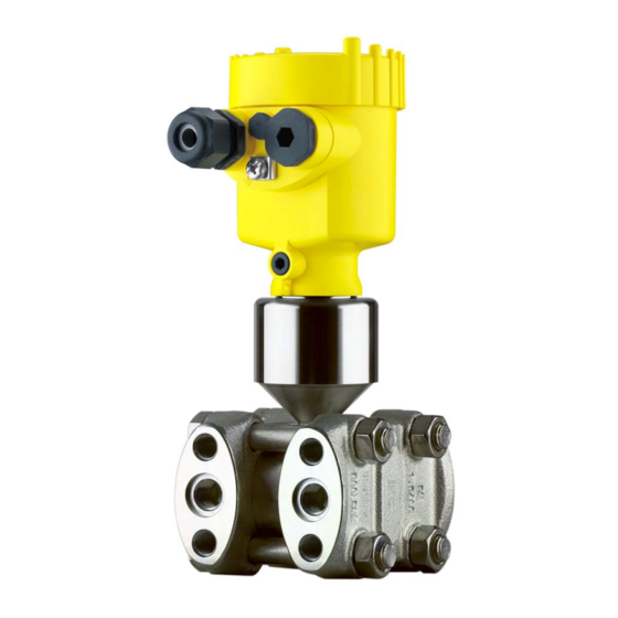
Ex-specific "Safety instructions" (with Ex versions) Certificate "Oil and grease-free for oxygen applications" (with respective versions) if necessary, further certificates The following illustration shows the components of VEGADIF 65: Constituent parts + – Fig. 1: VEGADIF 65 in basic version... -
Page 10: Principle Of Operation
Flow measurement – – Q ~ ∆p Q ~ ∆p Fig. 2: Flow measurement with VEGADIF 65 and DP flow element, Q = flow, Δp = differential pressure, Δp = p Orifice Pitot tube VEGADIF 65 • Foundation Fieldbus... - Page 11 – – ∆p ρ g Fig. 3: Level measurement with VEGADIF 65. Δp = differential pressure, density of the medium, g = acceleration of gravity Basic version with effective pressure lines Version with flange chemical seal Version with capillaries and cell chemical seals Differential pressure measurement...
- Page 12 3 Product description Density measurement ∆p – Fig. 5: Density measurement with VEGADIF 65, h = defined mounting distance, Δp = differential pressure, = density of the medium, g = acceleration of gravity VEGADIF 65 Interface measurement – Fig. 6: Interface measurement with VEGADIF 65...
- Page 13 Fieldbus specification serves as carrier of both power and digital data for multiple sensors. This cable can be operated in two versions: via an H1 interface card in the control system and additional power supply VEGADIF 65 • Foundation Fieldbus...
-
Page 14: Operation
Foundation Fieldbus". The appropriate certificates are also available there. A CD with the appropriate files and certificates can be ordered via e-mail under info@de.vega.com or by phone from one of the VEGA agencies under the order number "DRIVER.S". The backlight of the indicating and adjustment module is powered by the sensor. - Page 15 Not exposed to corrosive media Protected against solar radiation Avoiding mechanical shock and vibration Storage and transport Storage and transport temperature see chapter "Supplement - temperature Technical data - Ambient conditions" Relative humidity 20 … 85 % VEGADIF 65 • Foundation Fieldbus...
-
Page 16: Mounting
Fig. 9: Position of the filter element with single and double chamber housing Filter element for ventilation of the electronics housing Blind stopper Information: Make sure that the filter element is always free of buildup during operation. A high-pressure cleaner must not be used for cleaning. VEGADIF 65 • Foundation Fieldbus... -
Page 17: Instructions For Oxygen And Ultra-Pure Gas Applications
Danger of explosion! Pure gas applications We also offer oil and grease free instruments for special applications such as e.g. ultra-pure gas. There are no special restrictions with respect to the process conditions. VEGADIF 65 • Foundation Fieldbus... -
Page 18: Mounting And Connection Instructions
4 Mounting 4.3 Mounting and connection instructions When connecting the VEGADIF 65 to the measurement loop, take Connection plus/minus side note of the plus/minus side of the process component. The plus side is marked with a "+", the minus side with a "-" on the process component next to the oval flanges. - Page 19 Connection valve block The valve block is used for direct connection to the differential pressure transmitter. The following figure shows the connection of a 5- fold valve block. VEGADIF 65 • Foundation Fieldbus...
- Page 20 4 Mounting Fig. 12: Connection of a 5-fold valve block Process fitting Process fitting Check/Ventilate Check/Ventilate Valve for checking/ventilating Valve for checking/ventilating Inlet valve Inlet valve Breather valve VEGADIF 65 • Foundation Fieldbus...
-
Page 21: Measurement Setup Flow
4 Mounting 4.4 Measurement setup flow à Mount VEGADIF 65 above the measurement loop so that In gases condensate can drain off in the process cable. – Fig. 13: Measurement setup, flow measurement in gases VEGADIF 65 Three-fold valve block Blocking valves Orifice or impact pressure probe... - Page 22 VEGADIF 65 Precipitator Drain valves Three-fold valve block à Mount VEGADIF 65 below the measurement loop so that the In liquids effective pressure lines are always filled with liquid and gas bubbles can bubble up to the process line à For measurements in products with solid content such as e.g. dirty...
-
Page 23: Measurement Setup Level
Precipitator Drain valves Three-fold valve block 4.5 Measurement setup level à Mount VEGADIF 65 below the lower measurement connection so In open vessels with effective pressure line that the effective pressure lines are always filled with liquid à Minus side is open to the atmospheric pressure... - Page 24 VEGADIF 65 Minus side is open to the atmospheric pressure Blocking valve Precipitator Drain valve à Mount VEGADIF 65 directly to the vessel In open vessels with single chemical seal à Minus side is open to the atmospheric pressure min.
- Page 25 4 Mounting à Mount VEGADIF 65 below the lower measurement connection so In closed vessels with effective pressure lines that the effective pressure lines are always filled with liquid à Connect minus side always above the max. level à For measurements in products with solid content such as e.g. dirty...
- Page 26 Fig. 20: Measurement setup, level measurement in closed vessel VEGADIF 65 à Mount VEGADIF 65 below the lower measurement connection so In closed vessels with steam layering with ef- that the effective pressure lines are always filled with liquid fective pressure line VEGADIF 65 •...
- Page 27 Blocking valves VEGADIF 65 Precipitator Drain valves Three-fold valve block à Mount VEGADIF 65 directly to the vessel In closed vessels with superimposed steam à Connect minus side always above the max. level with single chemical à The condensate vessel ensures a constant pressure on the minus...
-
Page 28: Measurement Setup Density And Interface
The density measurement is carried out in the mode level measure- ment. à Mount VEGADIF 65 below the lower chemical seal à The ambient temperature should be the same for both capillaries Example for a density measurement: Distance between the two measurement points: 0.3 m Min. - Page 29 Min. density: 0.8 kg/dm Max. density: 1.0 kg/dm The min. adjustment is carried out for the differential pressure occuring with density 0.8: Δp = • g • h = 0.8 kg/dm³ • 9.81 m/s• 0.3 m VEGADIF 65 • Foundation Fieldbus...
- Page 30 • g • h = 1.0 kg/dm³ • 9.81 m/s • 0.3 m = 29.4 mbar à Mount VEGADIF 65 below the lower chemical seal à The ambient temperature should be the same for both capillaries – Fig. 24: Measurement setup with interface measurement...
-
Page 31: Measurement Setup Differential Pressure
VEGADIF 65 Three-fold valve block Blocking valves E.g. filter à Mount VEGADIF 65 below the measurement loop so that the In liquids effective pressure lines are always filled with liquid and gas bubbles can bubble up to the process line à... - Page 32 In gases, vapours and à Mount chemical seal with capillaries on top or laterally on the liquids pipeline à In vacuum applications: Mount VEGADIF 65 below the measure- ment loop à The ambient temperature should be the same for both capillaries –...
-
Page 33: Mounting External Housing
The socket housing can be displaced by 180° to the wall mounting plate. 4.9 Installation control Check the following after mounting the instrument: Did you tighten all screws? Closing screws and ventilation valves closed VEGADIF 65 • Foundation Fieldbus... -
Page 34: Connecting To Power Supply
If overvoltage surges are expected, overvoltage arresters should be installed according to Foundation Fieldbus specification Tip: We recommend VEGA overvoltage arrester B63-32. In hazardous areas you must take note of the respective regulations, conformity and type approval certificates of the sensors and power supply units. -
Page 35: Connection Procedure
10 Connect the screen to the internal ground terminal, connect the outer ground terminal to potential equalisation 11 Tighten the compression nut of the cable entry. The seal ring must completely encircle the cable 12 Screw the housing cover on VEGADIF 65 • Foundation Fieldbus... - Page 36 Loosen the four screws on the housing base with an Allen key size Remove the housing socket from the mounting plate Fig. 30: Components of the external housing Screws Wall mounting plate Cable gland VEGADIF 65 • Foundation Fieldbus...
-
Page 37: Single Chamber Housing
Remove approx. 5 cm of the cable mantle, strip approx. 1 cm insulation from the ends of the individual wires. After shortening the cable, fasten the type plate with sup- port back onto the cable. VEGADIF 65 • Foundation Fieldbus... - Page 38 Ground terminal for connection of the cable screen Spring-loaded terminals for Foundation Fieldbus connection Simulation switch ("on" = mode for simulation release) Wiring plan Display I 2 C Fig. 32: Wiring plan, single chamber housing Voltage supply/Signal output VEGADIF 65 • Foundation Fieldbus...
-
Page 39: Double Chamber Housing
Plug connector for VEGACONNECT (I²C interface) Ground terminal for connection of the cable screen Spring-loaded terminals for voltage supply Wiring plan I 2 C Fig. 34: Wiring plan with double chamber housing Voltage supply/Signal output VEGADIF 65 • Foundation Fieldbus... -
Page 40: Double Chamber Housing Ex D
Fig. 35: Connection compartment with double chamber housing Ex d Spring-loaded terminals for power supply and cable screen Ground terminal for connection of the cable screen Wiring plan Fig. 36: Wiring plan with double chamber housing Ex d Voltage supply/Signal output VEGADIF 65 • Foundation Fieldbus... -
Page 41: Version Ip 66/Ip 68, 1 Bar
Spring-loaded terminals for connection of the external indication VEGADIS Cable gland to the sensor Ground terminal for connection of the cable screen Spring-loaded terminals for Foundation Fieldbus connection Simulation switch ("on" = mode for simulation release) VEGADIF 65 • Foundation Fieldbus... -
Page 42: Switch On Phase
Fig. 40: Wiring plan external electronics Voltage supply 5.8 Switch on phase After VEGADIF 65 is connected to voltage supply or after voltage Switch on phase recurrence, the instrument carries out a self-check for approx. 30 seconds. The following steps are carried out:... - Page 43 Then the current measured value will be displayed and the corresponding digital output signal will be outputted to the cable. The values correspond to the actual measured level as well as to the set- tings already carried out, e.g. default setting. VEGADIF 65 • Foundation Fieldbus...
-
Page 44: Adjustment With The Indicating And Adjustment Module
Screw housing cover with inspection window tightly back on Removal is carried out in reverse order. The indicating and adjustment module is powered by the sensor, an additional connection is not necessary. VEGADIF 65 • Foundation Fieldbus... - Page 45 Fig. 41: Insert indicating and adjustment module Note: If you intend to retrofit the instrument with an indicating and adjustment module for continuous measured value indication, a higher cover with an inspection glass is required. VEGADIF 65 • Foundation Fieldbus...
-
Page 46: Adjustment System
The functions of the individual keys are shown in the above illustration. Approx. 10 minutes after the last pressing of a key, an automatic reset to measured value indication is triggered. Any values not confirmed with [OK] will not be saved. VEGADIF 65 • Foundation Fieldbus... -
Page 47: Parameter Description
"Outside parameter limits" appears. The editing procedure can be aborted with [ESC] or the displayed limit value can be accepted with [OK]. The VEGADIF 65 can be used for differential pressure, level, flow as Application well as density and interface measurement. The selection of the respective application is carried out in the menu item "Application". - Page 48 "Units of measurement" will be displayed. Activate the selection with [OK] and select the requested unit with [->] (in the example m). Confirm with [OK], the submenu "Density unit" appears. Unit of measurement Density unit ▶ kg/dm³ VEGADIF 65 • Foundation Fieldbus...
- Page 49 Select with [->], e.g. to accept the actual measured value 0.0035 bar. Position correction Accept current measured value? ▶ Accept Edit Confirm with [OK]. Position correction Offset -0.0035 bar 0.0000 bar Move to min. (zero) adjustment with [->]. VEGADIF 65 • Foundation Fieldbus...
- Page 50 Set the requested value with [+] and [->]. Confirm with [OK] and move to the menu overview with [ESC]. For an adjustment with pressure, simply enter the actual measured value indicated at the bottom of the display. VEGADIF 65 • Foundation Fieldbus...
- Page 51 For the min. adjustment with density, a filling of the vessel is not density necessary. The numeric examples are stated in chapter Mounting, Measurement setup density and interface of this instructions manual. Proceed as follows: Edit the % value in the menu item "Min. adjustment" with [OK]. VEGADIF 65 • Foundation Fieldbus...
- Page 52 Respective linearisation curves are stored for these vessels. They indicate the relation between the percentage level and the vessel volume. By activating the suitable curve, the percentage vessel volume is displayed correctly. VEGADIF 65 • Foundation Fieldbus...
- Page 53 This means that small changes in the measured differential pressure cause big changes in the output signal. The leak volume suppression stabilises the signal output. The VEGADIF 65 has two internal totalizers. For both you can adjust Total amounts counter and subtotalizer with volume or mass as count function as well as separately the unit.
- Page 54 Measured value presentation Application Unit of measurement Adjustment Damping Linearisation curve Creeping distance suppression Sensor-TAG Displayed value Display unit Language The following safety-relevant data are not read out or written: Copy sensor data Copy sensor data? VEGADIF 65 • Foundation Fieldbus...
- Page 55 Service Language No reset Application No reset Peak value The min. and max. temperature or pressure values are each reset to the actual value. Totalizer The total and part sum counter are reset to zero. VEGADIF 65 • Foundation Fieldbus...
- Page 56 Additional adjustment and diagnosis options such as e.g. scaling, simulation or trend curve presentation are shown in the following menu schematic. You will find a detailed description of these menu items in the operating instructions manual "Indicating and adjustment module". VEGADIF 65 • Foundation Fieldbus...
-
Page 57: Menu Schematic
0.0000 bar ▼ °C Max. adjustment Damping Linearisation curve Creeping distance suppres. ▶ 100.00 % Linear ▼ Extracted by root Activated 0.5000 bar Bidirectionally linear 0.0000 bar Bidirectionally extracted by root User programmable Sensor-TAG Sensor VEGADIF 65 • Foundation Fieldbus... - Page 58 Peak value Sensor status Trend curve Total sum counter 0.0000 10 p-min.: -5.8 mbar p-max.: 167.5 mbar Start trend curve? T-min.: -12.5 °C T-max.: +85.5 °C Modify settings? Part sum counter 0.0000 10 Modify settings? VEGADIF 65 • Foundation Fieldbus...
- Page 59 Copy sensor data? Enable? Info Basic settings Display Diagnostics Service ▶ Info Instrument type Calibration date Last change using PC Sensor characteristics 23rd October 2009 23rd October 2009 Display now? Serial number Software version 12345678 1.01 VEGADIF 65 • Foundation Fieldbus...
-
Page 60: Saving The Parameter Adjustment Data
They are hence available for multiple use or service purposes. If VEGADIF 65 is equipped with an indicating and adjustment module, the most important data can be read out of the sensor into the indicating and adjustment module. -
Page 61: Operating With Pactware And Other Adjustment Programs
USB cable to the PC VEGACONNECT Sensor VEGACONNECT exter- nally TWIST Fig. 44: Connection via VEGACONNECT externally I²C bus (com.) interface on the sensor I²C connection cable of VEGACONNECT VEGACONNECT USB cable to the PC VEGADIF 65 • Foundation Fieldbus... -
Page 62: Parameter Adjustment With Pactware
A detailed description is available in the online help of PACTware and the VEGA DTMs. Note: Keep in mind that for setup of VEGADIF 65, DTM-Collection in the actual version must be used. All currently available VEGA DTMs are included as a DTM Collection on a CD. -
Page 63: Setup
Flow measurement Level measurement Differential pressure measurement 8.2 Flow measurement In flow measurement, VEGADIF 65 is normally used without a Instructions chemical seal. Before adjusting VEGADIF 65, you have to clean the effective pressure lines and the instrument must be filled with the medium. - Page 64 VEGADIF 65 Three-fold valve block Precipitator 1.5 Drain valves 2.4 Inlet valves Breather valve 6.7 Vent valves on VEGADIF 65 A, B Blocking valves Prepare the adjustment Proceed as follows: Close valve 3 Fill measuring system with medium. Open valves A, B, 2, 4: Medium flows in If necessary, clean the differential pressure lines: - with gases by...
-
Page 65: Level Measurement
Carry out position correction, if flow can be blocked. In this case, step 5 is deleted. Then carry out adjustment, see chapter "Set parameters". 8.3 Level measurement For level measurements, the VEGADIF 65 in all versions is used. Instructions VEGADIF 65 with double chemical seal CSB is immediately ready for operation. - Page 66 Fig. 47: Preferred measurement setup for open vessels VEGADIF 65 Precipitator Drain valve 6.7 Vent valves on VEGADIF 65 Blocking valve Prepare the adjustment Proceed as follows: Fill the vessel to just over the lower tap. Fill measuring system with medium.
- Page 67 VEGADIF 65 Three-fold valve block Precipitator 1, 5 Drain valves 2, 4 Inlet valves 6, 7 Vent valves on VEGADIF 65 A, BBlocking valves Prepare the adjustment Proceed as follows: Fill the vessel to just above the lower tap Fill measuring system with medium...
- Page 68 Precipitator Condensate vessel 1, 5 Drain valves 2, 4 Inlet valves Breather valve 6, 7 Vent valves on VEGADIF 65 A, B Blocking valves Prepare the adjustment Proceed as follows: Fill the vessel to just above the lower tap Fill measuring system with medium Open valve A and B: Open block valves Fill the minus effective pressure line on the height of the...
-
Page 69: Density And Interface Measurement
For differential pressure measurements, VEGADIF 65 without chem- Instructions ical seal or with double chemical seal CSB is used. VEGADIF 65 with double chemical seal CSB is immediately ready for operation. Before adjusting VEGADIF 65 without chemical seal, the effective pressure lines must be cleaned and the instrument filled with medium. - Page 70 VEGADIF 65 Three-fold valve block Precipitator 1.5 Drain valves 2.4 Inlet valves Breather valve 6, 7 Vent valves on VEGADIF 65 A, B Blocking valves Prepare the adjustment Proceed as follows: Close valve 3 Fill measuring system with medium. Open valves A, B, 2, 4: Medium flows in.
- Page 71 Valves 1, 3, 5, 6 and 7 are closed Valves 2 and 4 open Valves A and B open (if available) Then carry out adjustment, see chapter "Set parameters". Valves 1, 3, 5: Configuration with 5 valves. VEGADIF 65 • Foundation Fieldbus...
-
Page 72: Maintenance And Fault Rectification
24 hour service hotline Should these measures not be successful, please call in urgent cases the VEGA service hotline under the phone no. +49 1805 858550. The hotline is available to you 7 days a week round-the-clock. Since we offer this service world-wide, the support is only available in the English language. - Page 73 à Carry out a software update or send instrument for repair E041 Hardware error à Exchange the instrument or send it in for repair Fault message can also appear if the pressure is higher than the nominal range. VEGADIF 65 • Foundation Fieldbus...
-
Page 74: Exchanging The Electronics Module
These are not included in the electronics module without serial number. The serial number is stated on the type label of VEGADIF 65 or on the delivery note. 9.5 Software update... -
Page 75: Instrument Repair
Connect the sensor to power supply and provide connection from PC to the instrument via VEGACONNECT. Start PACTware and provide connection to the sensor, e.g. via the VEGA project assistant. Close the parameter window of the sensor, as far as open. -
Page 76: Dismounting
Correct disposal avoids negative effects to persons and environment and ensures recycling of useful raw materials. Materials: see chapter "Technical data" If you have no way to dispose of the old instrument properly, please contact us concerning return and disposal. VEGADIF 65 • Foundation Fieldbus... -
Page 77: Supplement
PN 420: hexagon nut ISO 4032-M12-A4-bs 316Ti/316L Ground terminal Connection cable with version IP 68 PE, PUR, FEP (1 bar) Connection between IP 68 transmitter and external electronics housing Not with vacuum and absolute pressure measuring ranges < 1 bar VEGADIF 65 • Foundation Fieldbus... - Page 78 31.25 Kbit/s Transmission rate 10 mA, ±0.5 mA Current value Dynamic behaviour output ≤ 20 s Run-up time 100 % 63 % Fig. 52: Presentation of the dead time t and the time constant t VEGADIF 65 • Foundation Fieldbus...
- Page 79 Adjustment range of the min./max. adjustment relating to the nominal measuring range: Percentage value -10 … +110 % Pressure value -120 … +120 % Adjustment flow Values less than -1 bar cannot be set. Values less than -1 bar cannot be set. VEGADIF 65 • Foundation Fieldbus...
- Page 80 A position-dependent zero-point shift can be corrected (see also chapter "Adjust parameter"). Values less than -1 bar cannot be set. Instrument is rotated vertically to the diaphragm axis. For instruments with inert oil, the value doubles. VEGADIF 65 • Foundation Fieldbus...
- Page 81 4 … 20 mA. Specifications refer to the set span. Turn down (TD) is the ratio nominal measuring range/set span. Reference accuracy - all versions The following applies to square root extracted characteristics: The accuracy data of VEGADIF 65 are entered with factor 0.5 in the accuracy calculation of the flow. Reference accuracy - Basic version...
- Page 82 0,15 % -40°C -20°C 40°C 60°C 80°C 20°C -0,15 % Fig. 53: Thermal change, current output Influence of the system pressure on the zero point and span 316L, Alloy C276-, Alloy C276 gold-rhodium coated diaphragm VEGADIF 65 • Foundation Fieldbus...
- Page 83 Total accuracy Total Performance - Basic version The specification "Total Performance" comprises non-linearity incl. hysteresis and non-repeat- = 70 bar). ability, thermal change of the zero point and static pressure influence (p Total Performance VEGADIF 65 • Foundation Fieldbus...
- Page 84 (+50 … +140 °F). Up to 60 °C (140 °F). For measuring cells with PN 420 a lower temperature application limit of -10 °C (+14 °F) applies. For the version for oxygen application, note chapter "Oxygen applications". VEGADIF 65 • Foundation Fieldbus...
- Page 85 240 bar (24000 kPa) (16000 kPa) 420 bar (42000 kPa) 630 bar (63000 kPa) 420 bar (42000 kPa) Minus side: 100 bar (10000 kPa) 0.1 mbar Min. system pressure with all measuring (10 Pa ranges VEGADIF 65 • Foundation Fieldbus...
- Page 86 Spring-loaded terminals for wire cross-sec- tion Tested according to the guidelines of German Lloyd, GL directive 2. Tested according to EN 60068-2-27. Depending on the version M12 x 1, according to ISO 4400, Harting, 7/8" FF. VEGADIF 65 • Foundation Fieldbus...
- Page 87 2.5 mm² (AWG 14) Spring-loaded terminals for wire cross-sec- tion up to Indicating and adjustment module Voltage supply and data transmission through the sensor Depending on the version M12 x 1, according to ISO 4400, Harting, 7/8" FF. VEGADIF 65 • Foundation Fieldbus...
- Page 88 From measuring range 100 bar, 13 … 32 V DC. Instruments with gauge pressure measuring ranges cannot detect the am- bient pressure when submerged, e.g. in water. This can lead to falsification of the measured value. Only with instruments with absolute pressure ranges. VEGADIF 65 • Foundation Fieldbus...
- Page 89 Instruments with approvals can have different technical data depending on the version. That's why the associated approval documents have to be noted with these instruments. They are part of the delivery or can be downloaded under www.vega.com via "VEGA Tools" and "serial number search" as well as via "Downloads" and "Approvals".
-
Page 90: Information On Foundation Fieldbus
Channel = 2: Secondary Value 1 Channel = 3: Secondary Value 2 AI 3 Channel = 4: Temperature Fig. 54: Transducer Block VEGADIF 65 TB Transducer Block Function Block (AI =Analogue Input) Diagram, adjustment The following illustration shows the function of the adjustment:... - Page 91 X and Y values for the user defined linearization curve curve_points_21_30 X and Y values for the user defined linearization curve curve_points_31_33 X and Y values for the user defined linearization curve curve status VEGADIF 65 • Foundation Fieldbus...
- Page 92 Sensor value after the trim processing. Unit derives from 'Sensor_range.unit' sensor_sn Sensor serial number temperature Process temperature. Selected as input to AIFB by setting 'Channel' = 4. Unit derives from 'Temperature.unit' temperature_unit Unit code of 'Temperature', 'Max/Min_peak_temperature_value' °C, °F, K, °R VEGADIF 65 • Foundation Fieldbus...
- Page 93 Holds the maximum process temperature. Write access resets to current value. Unit derives from 'Temperature.unit' Write access resets to current value min_peak_temperature_value Holds the minimum process temperature. Write access resets to current value. Unit derives from 'Temperature.unit' Write access resets to current value VEGADIF 65 • Foundation Fieldbus...
-
Page 94: Dimensions
Double chamber version Aluminium housing ~ 87 mm (3.43") ~ 116 mm (4.57") ø 86 mm ø 86 mm (3.39") (3.39") M16x1,5 M20x1,5 M20x1,5/ ½ NPT M20x1,5/ ½ NPT Single chamber version Double chamber version VEGADIF 65 • Foundation Fieldbus... - Page 95 ~ 105 mm (4.13") ø 84 mm (3.31") M16x1,5 M20x1,5/ ½ NPT Single chamber version, Aluminium Single chamber version, stainless steel electropolished Single chamber version, stainless steel precision casting Double chamber housing Aluminium/stainless steel precision casting VEGADIF 65 • Foundation Fieldbus...
- Page 96 Version IP 68 with external electronics 68,3 mm (2.69") ø 55 mm (2.17") + – 90 mm (3.54") 110 mm (4.33") ~ 66 mm (2.6") ø 55 mm (2.17") Lateral cable outlet Axial cable outlet VEGADIF 65 • Foundation Fieldbus...
- Page 97 7/16-20 UNF M 10 (M12) + – 1/4-18 NPT RC1/4 100 mm 54 mm (2.13") (3.94") 98 mm (3.94") Fig. 61: Top: 10 mbar and 30 mbar measuring cell. Bottom: Measuring cell ≥ 100 mbar VEGADIF 65 • Foundation Fieldbus...
- Page 98 Oval flange, connection ¼-18 NPT or RC ¼, with lateral ventilation 1/4-18NPT 7/16-20 UNF RC1/4 M 10 + – 1/4-18 NPT RC1/4 54 mm 106 mm (2.13") (4.17") 100 mm (3.94") Fig. 62: 10 mbar and 30 mbar measuring cell VEGADIF 65 • Foundation Fieldbus...
- Page 99 (2.13") (2.13") 98 mm 98 mm (3.94") (3.94") Fig. 63: left: Process fitting VEGADIF 65 prepared for chemical seal assembly. right: Position of the copper ring seal Chemical seal connection Copper ring seal Cup diaphragm VEGADIF 65 • Foundation Fieldbus...
- Page 100 Les lignes de produits VEGA sont globalement protégées par des droits de propriété intellectuelle. Pour plus d'informations, on pourra se référer au site http://www.vega. VEGA lineas de productos están protegidas por los derechos en el campo de la propiedad industrial. Para mayor información revise la pagina web http://www.vega.com Линии...
- Page 101 - In gases 21 Valve block 19 - In liquids 22 - In vapours 21 Functional principle 12 Wiring plan - Double chamber housing 39 - External electronics 42 Hotline 72 - Single chamber housing 38 VEGADIF 65 • Foundation Fieldbus...
- Page 102 Index VEGADIF 65 • Foundation Fieldbus...
- Page 103 Index VEGADIF 65 • Foundation Fieldbus...
- Page 104 All statements concerning scope of delivery, application, practical use and operating conditions of the sensors and processing systems correspond to the information avail- able at the time of printing. © VEGA Grieshaber KG, Schiltach/Germany 2011 36130-EN-110510 Subject to change without prior notice...
Need help?
Do you have a question about the VEGADIF 65 and is the answer not in the manual?
Questions and answers