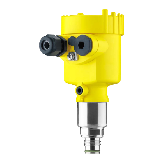
Vega VEGABAR 83 Quick Setup Manual
Pressure transmitter with metallic measuring cell
Hide thumbs
Also See for VEGABAR 83:
- Operating instructions manual (108 pages) ,
- Quick setup manual (20 pages) ,
- Product information (16 pages)

Related Manuals for Vega VEGABAR 83


Summary of Contents for Vega VEGABAR 83
- Page 1 Quick setup guide Pressure transmitter with metallic measuring cell VEGABAR 83 4 … 20 mA/HART Document ID: 46313...
-
Page 2: Table Of Contents
Operating Instructions Manual as well as the Safety Manual that comes with instruments with SIL qualification. These manuals are available on our homepage. Operating instructions VEGABAR 83 - 4 … 20 mA/HART: Document-ID 45034 Editing status of the quick setup guide: 2023-09-06 VEGABAR 83 • 4 … 20 mA/HART... -
Page 3: For Your Safety
During work on and with the device, the required personal protective equipment must always be worn. Appropriate use The VEGABAR 83 is a pressure transmitter for process pressure and hydrostatic level measurement. You can find detailed information about the area of application in chapter " Product description". Operational reliability is ensured only if the instrument is properly used according to the specifications in the operating instructions manual as well as possible supplementary instructions. -
Page 4: Namur Recommendations
Please help us fulfil this obligation by observing the environmental instructions in this manual: • Chapter " Packaging, transport and storage" • Chapter " Disposal" Exception: Versions with measuring ranges from 250 bar. These are subject of the EU Pressure Device Directive. VEGABAR 83 • 4 … 20 mA/HART... -
Page 5: Product Description
• Move to " www.vega.com" and enter in the search field the serial number of your instrument. • Scan the QR code on the type label. • Open the VEGA Tools app and enter the serial number under " Documentation". VEGABAR 83 • 4 … 20 mA/HART... -
Page 6: Mounting
Aluminium - single chamber Stainless steel single chamber (electropolished) Plastic double chamber Aluminium, stainless steel double chamber housing (precision casting) Filter element With the following instruments a blind plug is installed instead of the filter element: VEGABAR 83 • 4 … 20 mA/HART... - Page 7 3 Mounting • Instruments in protection IP66/IP68 (1 bar) - ventilation via capillar- ies in non-detachable cable • Instruments with absolute pressure VEGABAR 83 • 4 … 20 mA/HART...
-
Page 8: Connecting To Power Supply
6. Insert the wire ends into the terminals according to the wiring plan Note: Solid cores as well as flexible cores with wire end sleeves are insert- ed directly into the terminal openings. In case of flexible cores without end sleeves, press the terminal from above with a small screwdriver, the terminal opening is then free. When the screwdriver is released, the terminal closes again. 7. Check the hold of the wires in the terminals by lightly pulling on them 8. Connect the shielding to the internal ground terminal, connect the external ground terminal to potential equalisation VEGABAR 83 • 4 … 20 mA/HART... -
Page 9: Single Chamber Housing
Fig. 4: Connection compartment - double chamber housing Voltage supply, signal output For display and adjustment module or interface adapter For external display and adjustment unit Ground terminal for connection of the cable screening VEGABAR 83 • 4 … 20 mA/HART... -
Page 10: Set Up With The Display And Adjustment Module
3. Screw housing lid with inspection window tightly back on Disassembly is carried out in reverse order. The display and adjustment module is powered by the sensor, an ad- ditional connection is not necessary. Fig. 5: Installing the display and adjustment module in the electronics compart- ment of the single chamber housing VEGABAR 83 • 4 … 20 mA/HART... -
Page 11: Parameter Adjustment - Quick Setup
Units In this menu item you determine the adjustment and temperature units of the instrument. Depending on the selected application in the menu item " Application", different adjustment units are available. VEGABAR 83 • 4 … 20 mA/HART... - Page 12 Enter the percentage value and the corresponding value for the min. level. The quick setup is finished. Parameterization example VEGABAR 83 always measures pressure independently of the pro- cess variable selected in the menu item " Application". To output the selected process variable correctly, an allocation of the output signal to 0 % and 100 % must be carried out (adjustment).
-
Page 13: Parameter Adjustment - Extended Adjustment
These settings can be made ahead of time without the instrument having to be installed. Parameter adjustment - Extended adjustment For technically demanding measuring points, you can carry out extended settings in " Extended adjustment". Main menu The main menu is divided into five sections with the following func- tions: Setup: Settings e. g. for measurement loop name, application, units, position correction, adjustment, signal output, disable/enable opera- tion Display: Settings, e.g., for language, measured value display, lighting Diagnosis: Information, for example, of device status, peak indicator, simulation Additional adjustments: date/time, reset, copy function VEGABAR 83 • 4 … 20 mA/HART... -
Page 14: Menu Overview
20 … 4 mA Failure mode: ≤ 3.6 mA, ≥ 20 mA, last ≤ 3.6 mA measured value Current output - Min./Max. Min. current: 3.8 mA, 4 mA 3.8 mA Max. current: 20 mA, 20.5 mA 20.5 mA Lock adjustment Blocked, released Released Parameter only active if the instrument is connected to the Secondary Device VEGABAR 83 • 4 … 20 mA/HART... - Page 15 0 … 100 °C correspond to 4 … 20 mA HART mode HART address, current output Address 00, analogue current output Special parameters Service-Login No reset Info Menu item Parameter Device name VEGABAR 83 Instrument version Hardware and software version Factory calibration date Date VEGABAR 83 • 4 … 20 mA/HART...
- Page 16 5 Set up with the display and adjustment module Menu item Parameter Sensor characteristics Order-specific characteristics VEGABAR 83 • 4 … 20 mA/HART...
-
Page 17: Set Up With Smartphone/Tablet, Pc/Notebook Via Bluetooth
The default setting of the sensor PIN is " 0000". First of all you have to change the sensor PIN in the adjustment menu of the sensor, e.g. to " 1111": 1. Go to setup via the extended operation 2. Lock operation by changing sensor PIN 3. Enable operation again by entering the sensor PIN once more VEGABAR 83 • 4 … 20 mA/HART... -
Page 18: Connecting
Bluetooth-capable instru- ments in the area. PC/Notebook Start PACTware and the VEGA project assistant. Select the device search via Bluetooth and start the search function. The device auto- matically searches for Bluetooth-capable devices in the vicinity. - Page 19 6 Set up with smartphone/tablet, PC/notebook via Bluetooth App view Fig. 9: Example of an app view - Setup sensor adjustment VEGABAR 83 • 4 … 20 mA/HART...
-
Page 20: Supplement
Ʋ for U 24 V DC (18 V < U < 35 V) ≤ 1.0 V (16 … 400 Hz) Load resistor Ʋ Calculation )/0.022 A Ʋ Example - with U = 24 V DC (24 V - 9.6 V)/0.022 A = 655 Ω IP66/IP68 (0.2 bar), only with absolute pressure. VEGABAR 83 • 4 … 20 mA/HART... - Page 21 Notes VEGABAR 83 • 4 … 20 mA/HART...
- Page 22 Notes VEGABAR 83 • 4 … 20 mA/HART...
- Page 23 Notes VEGABAR 83 • 4 … 20 mA/HART...
- Page 24 Subject to change without prior notice © VEGA Grieshaber KG, Schiltach/Germany 2023 VEGA Grieshaber KG Am Hohenstein 113 Phone +49 7836 50-0 77761 Schiltach E-mail: info.de@vega.com...
Need help?
Do you have a question about the VEGABAR 83 and is the answer not in the manual?
Questions and answers