Vega VEGADIF 65 Operating Instructions Manual
4...20 ma/hart differential pressure transmitter
Hide thumbs
Also See for VEGADIF 65:
- Operating instructions manual (104 pages) ,
- Operating instructions manual (16 pages) ,
- Operating instructions manual (16 pages)

Related Manuals for Vega VEGADIF 65


Summary of Contents for Vega VEGADIF 65
-
Page 1: Operating Instructions
Operating Instructions VEGADIF 65 4 … 20 mA/HART Document ID: 36128 Differential pressure... -
Page 2: Table Of Contents
Insert indicating and adjustment module... 41 Adjustment system ......43 VEGADIF 65 • 4 … 20 mA/HART... - Page 3 To ensure reliable setup and operation of your instrument, we offer accessories and replacement parts. The corresponding instructions manuals are: 27720 - External indication VEGADIS 61 34296 - Protective cover 36132 - Electronics module DF60 for VEGADIF 65 VEGADIF 65 • 4 … 20 mA/HART...
-
Page 4: About This Document
This symbol indicates special instructions for Ex applications. List The dot set in front indicates a list with no implied sequence. à Action This arrow indicates a single action. Sequence Numbers set in front indicate successive steps in a procedure. VEGADIF 65 • 4 … 20 mA/HART... -
Page 5: For Your Safety
During work on and with the device the required personal protective equipment must always be worn. 2.2 Appropriate use VEGADIF 65 is a differential pressure transmitter for measurement of flow, level, differential pressure, density and interface. You can find detailed information on the application range in chapter "Product description". -
Page 6: Safety Label On The Instrument
2.6 CE conformity This device fulfills the legal requirements of the applicable EC guidelines. By attaching the CE mark, VEGA provides a confirmation of successful testing. You can find the CE conformity declaration in the download area of www.vega.com. - Page 7 2 For your safety Chapter "Packaging, transport and storage" Chapter "Disposal" VEGADIF 65 • 4 … 20 mA/HART...
-
Page 8: Product Description
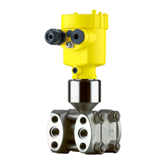
Ex-specific "Safety instructions" (with Ex-versions) Certificate "Oil and grease-free for oxygen applications" (with respective versions) if necessary, further certificates The following illustration shows the components of VEGADIF 65: Components + – Fig. 1: VEGADIF 65 in basic version Housing cover, optionally with integrated indicating and adjustment module... -
Page 9: Principle Of Operation
– – Q ~ ∆p Q ~ ∆p Fig. 2: Flow measurement with VEGADIF 65 and effective pressure transmitter, Q = flow, Δp = differential pressure, Δp = p Orifice Dynamic pressure probe VEGADIF 65 • 4 … 20 mA/HART... - Page 10 – – ∆p ρ g Fig. 3: Level measurement with VEGADIF 65. Δp = differential pressure, density of the medium, g = acceleration of gravity Basic version with effective pressure lines Version with flange isolating diaphragm Version with capillaries and cell isolating diaphragms Differential pressure measurement...
- Page 11 3 Product description Density measurement ∆p – Fig. 5: Density measurement with VEGADIF 65, h = defined mounting distance, Δp = differential pressure, = density of the medium, g = acceleration of gravity VEGADIF 65 Interface measurement – Fig. 6: Interface measurement with VEGADIF 65...
- Page 12 The optional background lighting of the indicating and adjustment module is powered by the sensor. A certain level of operating voltage is required for this. You can find the exact voltage specifications in chapter "Technical data". VEGADIF 65 • 4 … 20 mA/HART...
-
Page 13: Operation
This function is generally not available for approved instruments. 3.3 Operation VEGADIF 65 can be adjusted with different adjustment media: with indicating and adjustment module with the suitable VEGA DTM in conjunction with an adjustment software according to the FDT/DTM standard, e.g. PACTware and with manufacturer-specific adjustment programs AMS™... - Page 14 3 Product description Avoiding mechanical shock and vibration Storage and transport temperature see chapter "Supplement - Storage and transport temperature Technical data - Ambient conditions" Relative humidity 20 … 85 % VEGADIF 65 • 4 … 20 mA/HART...
-
Page 15: Mounting
Use the recommended cables (see chapter "Connecting to power Moisture supply") and tighten the cable gland. You can give your VEGADIF 65 additional protection against moisture penetration by leading the connection cable downward in front of the cable entry. Rain and condensation water can thus drain off. This applies mainly to outdoor mounting as well as installation in areas where high humidity is expected (e.g. -
Page 16: Special Application Conditions
"O₂" will be visible on the process fitting. Penetration of oil, grease and dirt should be avoided. Danger of explosion! In addition, VEGA offers oil and grease-free instruments for special Pure gas applications applications such as e.g. pure gas. There are no special restrictions in respect to the process conditions. -
Page 17: Flow Measurement
4 Mounting 4.3 Flow measurement à Mount VEGADIF 65 above the measurement loop so that In gases condensate can drain off in the process cable. – Fig. 10: Measurement setup, flow measurement in gases VEGADIF 65 Three-fold valve block Block valves Orifice or impact pressure probe... - Page 18 VEGADIF 65 Precipitator Drain valves Three-fold valve block à Mount VEGADIF 65 below the measurement loop so that the In liquids effective pressure lines are always filled with liquid and gas bubbles can bubble up to the process line à For measurements in products with solid content such as e.g. dirty...
-
Page 19: Level Measurement
Precipitator Drain valves Three-fold valve block 4.4 Level measurement à Mount VEGADIF 65 below the lower measurement connection so In open vessels with that the effective pressure lines are always filled with liquid effective pressure line à Minus side is open to the atmospheric pressure... - Page 20 Fig. 14: Measurement setup, level measurement in the open vessel VEGADIF 65 Minus side is open to the atmospheric pressure à Mount VEGADIF 65 below the lower measurement connection so In closed vessels with that the effective pressure lines are always filled with liquid effective pressure lines...
- Page 21 Block valves VEGADIF 65 Precipitator Drain valves Three-fold valve block à Mount VEGADIF 65 directly to the vessel In closed vessels with unilateral pressure à Connect minus side always above the max. level transmitter à For measurements in products with solid content such as e.g. dirty...
- Page 22 Fig. 17: Measurement setup, level measurement in closed vessel VEGADIF 65 à Mount VEGADIF 65 below the lower measurement connection so In closed vessels with that the effective pressure lines are always filled with liquid steam layering with ef- fective pressure line à...
- Page 23 Block valves VEGADIF 65 Precipitator Drain valves Three-fold valve block à Mount VEGADIF 65 directly to the vessel In closed vessels with steam layering with uni- à Connect minus side always above the max. level lateral pressure trans- à The condensate vessel ensures a constant pressure on the minus...
-
Page 24: Density And Interface Measurement
4.5 Density and interface measurement Density and interface measurement are carried out in level measure- ment mode. à Mount VEGADIF 65 below the lower isolating diaphragm Density measurement à The ambient temperature should be the same for both capillaries Information: The density measurement is only ensured with constant level. - Page 25 Δp = 30.6 mbar. With density change: e.g. measured Δp = 36.7 mbar corresponds to density 1.2, measured Δp = 24.5 mbar corresponds to density VEGADIF 65 à Mount VEGADIF 65 below the lower isolating diaphragm Interface measurement à The ambient temperature should be the same for both capillaries Information: Interface measurement is ensured only when the filling level is...
-
Page 26: Differential Pressure Measurement
VEGADIF 65 Three-fold valve block Block valves E.g. filter à Mount VEGADIF 65 below the measurement loop so that the In liquids effective pressure lines are always filled with liquid and gas bubbles can bubble up to the process line à... - Page 27 à Mount isolating diaphragm with capillaries on top or laterally on the In gases, vapours and pipeline liquids à In vacuum applications: Mount VEGADIF 65 below the measure- ment loop à The ambient temperature should be the same for both capillaries –...
-
Page 28: Wall Or Tube Mounting
3-fold valve block Oval flange adapter Screw 4.8 External housing Mark the holes according to the following drilling template Wall mounting Depending on the mounting surface, fasten the wall mounting plate with 4 screws VEGADIF 65 • 4 … 20 mA/HART... -
Page 29: Mounting Control
The socket housing can be displaced by 180° to the wall mounting plate. 4.9 Mounting control Check the following after mounting the instrument: Did you tighten all screws? Closing screws and ventilation valves closed VEGADIF 65 • 4 … 20 mA/HART... -
Page 30: Connect To Power Supply
The signal conditioning instruments VEGAMET 624 and 625 as well as VEGASCAN 693 have a digital sensor recognition. When connecting VEGADIF 65, a software version from 1.92 is required with the signal conditioning instrument. For software update move under "www.vega. -
Page 31: Connection Procedure
Remove approx. 10 cm of the cable mantle, strip approx. 1 cm insulation from the individual wires Insert the cable through the cable gland into the sensor Lift the opening levers of the terminals with a screwdriver (see following illustration) VEGADIF 65 • 4 … 20 mA/HART... - Page 32 The electrical connection is finished. Fig. 27: Connection steps 6 and 7 Proceed as follows: IP 68 version with exter- nal housing Loosen the four screws on the housing socket with an Allen key size 4 VEGADIF 65 • 4 … 20 mA/HART...
- Page 33 5 cm of the cable mantle, strip approx. 1 cm insulation from the ends of the individual wires. After shortening the cable, fasten the type plate with sup- port back onto the cable. VEGADIF 65 • 4 … 20 mA/HART...
-
Page 34: Single Chamber Housing
Spring-loaded terminals for connection of the external indication VEGADIS Ground terminal for connection of the cable screen Spring-loaded terminals for voltage supply Wiring plan Display I 2 C Fig. 30: Wiring plan, single chamber housing Voltage supply/Signal output VEGADIF 65 • 4 … 20 mA/HART... -
Page 35: Double Chamber Housing
Plug connector for VEGACONNECT (I²C interface) Ground terminal for connection of the cable screen Spring-loaded terminals for voltage supply Wiring plan I 2 C Fig. 32: Wiring plan, double chamber housing Voltage supply/Signal output VEGADIF 65 • 4 … 20 mA/HART... -
Page 36: Double Chamber Housing Ex D
Fig. 33: Connection compartment double chamber housing Ex d Spring-loaded terminals for power supply and cable screen Ground terminal for connection of the cable screen Wiring plan Fig. 34: Wiring plan double chamber housing Ex d Voltage supply/Signal output VEGADIF 65 • 4 … 20 mA/HART... -
Page 37: Version Ip 66/Ip 68, 1 Bar
Fig. 36: Electronics and connection compartment Plug connector for VEGACONNECT (I²C interface) Spring-loaded terminals for connection of the external indication VEGADIS Cable gland to VEGABAR Ground terminal for connection of the cable screen Spring-loaded terminals for voltage supply VEGADIF 65 • 4 … 20 mA/HART... -
Page 38: Switch On Phase
I 2 C Fig. 38: Wiring plan external electronics Power supply 5.8 Switch on phase After connecting VEGADIF 65 to power supply or after a voltage Switch on phase recurrence, the instrument carries out a self-check for approx. 30 seconds: Internal check of the electronics VEGADIF 65 •... - Page 39 Output signal jumps for approx. 15 seconds to the set fault current Then the corresponding current is outputted to the cable (the value corresponds to the actual level as well as the settings already carried out, e.g. factory setting). VEGADIF 65 • 4 … 20 mA/HART...
-
Page 40: Adjustment With The Indicating And Adjustment Module
Screw housing cover with inspection window tightly back on Removal is carried out in reverse order. The indicating and adjustment module is powered by the sensor, an additional connection is not necessary. VEGADIF 65 • 4 … 20 mA/HART... - Page 41 Fig. 39: Insert indicating and adjustment module Note: If you intend to retrofit the instrument with an indicating and adjustment module for continuous measured value indication, a higher cover with an inspection glass is required. VEGADIF 65 • 4 … 20 mA/HART...
-
Page 42: Adjustment System
The functions of the individual keys are shown in the above illustration. Approx. 10 minutes after the last pressing of a key, an automatic reset to measured value indication is triggered. Any values not confirmed with [OK] will not be saved. VEGADIF 65 • 4 … 20 mA/HART... -
Page 43: Set Parameters
[ESC] or the displayed limit value can be accepted with [OK]. VEGADIF 65 can be used for differential pressure, level as well as flow Application measurement. The selection is made in the menu item "Application". - Page 44 [->] (in the example m). Confirm with [OK], the submenu "Density unit" appears. Unit of measurement Density unit kg/dm³ ▶ Select the requested unit, e.g. kg/dm³ with [->] and confirm with [OK], the submenu "Density" appears. VEGADIF 65 • 4 … 20 mA/HART...
- Page 45 -0.0035 bar 0.0000 bar Move to min. (zero) adjustment with [->]. The current measured value was corrected to 0, the corrective value is available in the display as offset value with sign reversal. VEGADIF 65 • 4 … 20 mA/HART...
- Page 46 For an adjustment with pressure, simply enter the actual measured value indicated at the bottom of the display. The span adjustment is finished. Proceed as follows: Min. adjustment with level Edit the % value in the menu item "Min. adjustment" with [OK]. VEGADIF 65 • 4 … 20 mA/HART...
- Page 47 Set the requested bar value with [+] and [->]. Confirm with [+] and move to max. adjustment with [->]. For an adjustment with flow, simply enter the actual measured value indicated at the bottom of the display. VEGADIF 65 • 4 … 20 mA/HART...
- Page 48 The flow is proportional to the square of the pressure difference on the orifice or the back pressure probe. To establish a linear relation, a root extraction is necessary. VEGADIF 65 has this root extraction function. It is selected in the menu item "Linearization curve".
- Page 49 The leak volume suppression stabilises the signal output. The VEGADIF 65 has two internal totalizers. For both you can adjust Total amounts counter volume or mass as count function as well as separately the unit.
- Page 50 Zero/Min. adjustment Measuring range begin Span/Max. adjustment Measuring range end 1 kg/l Density Density unit kg/l Damping linear Linearisation Sensor-TAG Sensor Displayed value Differential pressure Display Display unit Mass/kg 0.00 to 100.0 Scaling VEGADIF 65 • 4 … 20 mA/HART...
- Page 51 Optional settings simulation or trend curve presentation are shown in the following menu schematic. You will find a detailed description of these menu items in the operating instructions manual "Indicating and adjustment module". VEGADIF 65 • 4 … 20 mA/HART...
-
Page 52: Menu Schematic
Temperature unit -0.0035 bar 0.0000 bar 0.0000 bar 0.0000 bar ▼ °C Max. adjustment Linearisation curve Damping Sensor-TAG linear ▶ 100.00 % Horizontal cylindrical tank Sensor Spherical tank 0.5000 bar 0.0000 bar User programmable VEGADIF 65 • 4 … 20 mA/HART... - Page 53 Basic adjustment ▶ Display Diagnostics Service Info Displayed value Displayed value Display unit ▼ Scaling 0 % = 0.0 ▼ ▼ Differential pressure Scaled Volume ▼ 100 % = 100.0 Lighting ▼ Switched off VEGADIF 65 • 4 … 20 mA/HART...
- Page 54 Start simulation Select reset Deutsch Fail.mode: < 3.6 mA ▼ Min. current: 3.8 mA ▼ max. current: 20.5 mA ▼ HART mode Copy sensor data ▼ Deactivated! Standard Copy sensor data? Enable? Address 0 VEGADIF 65 • 4 … 20 mA/HART...
- Page 55 Info Basic adjustment Display Diagnostics Service ▶ Info Sensor type Date of manufacture Last change using PC Sensor characteristics 21. March 2009 21. March 2009 Display now? Serial number Software version 12345678 1.01 VEGADIF 65 • 4 … 20 mA/HART...
-
Page 56: Saving The Parameter Adjustment Data
They are hence available for multiple use or service purposes. If VEGADIF 65 is equipped with an indicating and adjustment module, the most important data can be read out of the sensor into indicating and adjustment module. -
Page 57: Operating With Pactware And Other Adjustment Programs
USB cable to the PC VEGACONNECT Sensor VEGACONNECT exter- nally TWIST Fig. 42: Connection via VEGACONNECT externally I²C bus (com.) interface on the sensor I²C connection cable of VEGACONNECT VEGACONNECT USB cable to the PC VEGADIF 65 • 4 … 20 mA/HART... -
Page 58: Parameter Adjustment With Pactware
With power supply units with integrated HART resistance (internal resistance approx. 250 Ω), an additional external resistance is not necessary. This applies, e. g. to the VEGA instruments VEGATRENN 149A, VEGADIS 371, VEGAMET 381. Common Ex separators are also usually equipped with a sufficient current limitation resistance. In such cases, VEGACONNECT 4 can be connected parallel to the 4 …... -
Page 59: Parameter Adjustment With Ams™ And Pdm
7 Operating with PACTware and other adjustment programs Note: Keep in mind that for setup of VEGADIF 65, DTM-Collection in the actual version must be used. All currently available VEGA DTMs are included as a DTM Collection on a CD. They can be purchased for a token fee from the responsible VEGA agency. -
Page 60: Set Up
Flow measurement Level measurement Differential pressure measurement 8.2 Flow measurement In flow measurement, normally VEGADIF 65 is used without isolating Instructions diaphragm. Before adjusting VEGADIF 65, you have to clean the effective pressure lines and the instrument must be filled with the medium. - Page 61 Close valve 4: Minus side will be closed Open valve 3: Equalisation plus and minus side Briefly open valve 6 and 7, then close again: Fill the measuring instrument completely with the medium and remove air Arrangement with 5 valves. VEGADIF 65 • 4 … 20 mA/HART...
-
Page 62: Level Measurement
Carry out position correction, if flow can be blocked. In this case, step 5 is deleted. Then carry out adjustment, see chapter "Set parameters". 8.3 Level measurement For level measurements, the VEGADIF 65 in all versions is used. Instructions VEGADIF 65 with bilateral isolating diaphragm CSB is immediately ready for operation. - Page 63 Briefly open valve 6, then close it: Fill the measuring instrument completely with the medium and remove air. Set measurement loop to operation Now: Valve A open and valve 6 closed Then carry out adjustment, see below. VEGADIF 65 • 4 … 20 mA/HART...
- Page 64 VEGADIF 65 Three-fold valve block Precipitator 1, 5 Drain valves 2, 4 Inlet valves 6, 7 Vent valves on VEGADIF 65 A, B Block valves Proceed as follows: Prepare the adjustment Fill the vessel to just above the lower tap...
- Page 65 Precipitator Condensate vessel 1, 5 Drain valves 2, 4 Inlet valves Breather valve 6, 7 Vent valves on VEGADIF 65 A, B Block valves Proceed as follows: Prepare the adjustment Fill the vessel to just above the lower tap Fill measuring system with medium Open valve A and B: Open block valves Fill the minus effective pressure line on the height of the...
-
Page 66: Density And Interface Measurement
8.4 Density and interface measurement For density and interface measurements, VEGADIF 65 with bilateral isolating diaphragm CSB is used. VEGADIF 65 in this version is immediately ready for operation. 8.5 Differential pressure measurement For differential pressure measurements, VEGADIF 65 without isolating Instructions diaphragm or with bilateral isolating diaphragm CSB is used. - Page 67 VEGADIF 65 Three-fold valve block Precipitator 1.5 Drain valves 2.4 Inlet valves Breather valve 6, 7 Vent valves on VEGADIF 65 A, B Block valves Proceed as follows: Prepare the adjustment Close valve 3 Fill measuring system with medium. Open valves A, B, 2, 4: Medium flows in.
- Page 68 Valves 1, 3, 5, 6 and 7 are closed Valves 2 and 4 open Valves A and B open (if available) Then carry out adjustment, see chapter "Set parameters". Valves 1, 3, 5: Configuration with 5 valves. VEGADIF 65 • 4 … 20 mA/HART...
-
Page 69: Maintenance And Fault Rectification
DTM. In many cases, the causes can be determined and faults rectified in this way. However, should these measures not be successful, call the VEGA 24 hour service hotline service hotline in urgent cases under the phone no. +49 1805 858550. -
Page 70: Exchanging The Electronics Module
VEGA agency serving you. The sensor serial number is required to order an exchange electronics. You will find this number on the type label of VEGADIF 65 or on the delivery note. -
Page 71: Instrument Repair
Prepare update to the instrument via VEGACONNECT. Start PACTware and provide connection to the sensor, e.g. via the VEGA project assistant. Close the parameter window of the sensor, as far as open. Go in the PACTware menu bar to "Instrument data", "Additional Load software into sen- functions"... -
Page 72: Dismounting
Correct disposal avoids negative effects to persons and environment and ensures recycling of useful raw materials. Materials: see chapter "Technical data" If you have no possibility to dispose of the old instrument professionally, please contact us concerning return and disposal. VEGADIF 65 • 4 … 20 mA/HART... -
Page 73: Supplement
Connection between IP 68 transmitter and external electronics housing Type plate support with IP 68 version on PE hard cable Halocarbon oil generally with oxygen applications, not with vacuum and absolute pressure measuring range < 1 bar VEGADIF 65 • 4 … 20 mA/HART... - Page 74 Step response time ≤ 250 ms (ti: 0 s, 10 … 90 %) Version, nominal measuring range Dead time t Time constant t Basic version 10 bar and 30 bar 100 ms 250 ms VEGADIF 65 • 4 … 20 mA/HART...
- Page 75 Reference conditions according to DIN EN 61298-1 Temperature +18 … +30 °C (+64 … +86 °F) Relative humidity 45 … 75 % Air pressure 860 … 1060 mbar/86 … 106 kPa (12.5 … 15.4 psig) VEGADIF 65 • 4 … 20 mA/HART...
- Page 76 4 … 20 mA. Specifications refer to the set span. Turn down (TD) is the ratio nominal measuring range/set span. Reference accuracy - all versions This applies to the characteristics extracted by root: The accuracy data of VEGADIF 65 are entered with factor 0.5 in the accuracy calculation of the flow Reference accuracy - Basic version...
- Page 77 ±0.14 % of URL/ ±0.14 % of URL/ ±0.14 % of URL/ tem pressure to the 7 bar 70 bar 70 bar 70 bar span Measuring cell 3 bar 16 bar 40 bar VEGADIF 65 • 4 … 20 mA/HART...
- Page 78 All specifications apply to the temperature range +10 … +60 °C (+50 … +140 °F). For measuring ranges ≥ 500 mbar up to TD 2 : 1 All specifications apply to the temperature range +10 … +60 °C (+50 … +140 °F). VEGADIF 65 • 4 … 20 mA/HART...
- Page 79 Up to 60 °C (140 °F). For measuring cells with PN 420 a lower temperature application limit of -10 °C (+14 °F) applies. For the version for oxygen application, note chapter "Oxygen applications". VEGADIF 65 • 4 … 20 mA/HART...
- Page 80 Acceleration 100 g/6 ms Tested according to the directives of the German Lloyd, GL directive 2. Not in the case of double chamber housing of precision cast stainless steel. Tested according to EN 60068-2-27. VEGADIF 65 • 4 … 20 mA/HART...
- Page 81 1 x closing cap ½ NPT, 1 x blind stopper ½ NPT, plug M12 x 1 for VEGADIS 61 (optional) Connection cable Depending on the version M12 x 1, according to DIN 43650, Harting, 7/ 8" FF. VEGADIF 65 • 4 … 20 mA/HART...
- Page 82 Indication Adjustment elements 4 keys Protection rating unassembled IP 20 mounted into the sensor without cover IP 40 Depending on the version M12 x 1, according to DIN 43650, Harting, 7/ 8" FF. VEGADIF 65 • 4 … 20 mA/HART...
- Page 83 Protection rating Housing, standard IP 66/IP 67 Instruments with gauge pressure measuring ranges cannot detect the am- bient pressure when submerged, e.g. in water. This can lead to falsification of the measured value. VEGADIF 65 • 4 … 20 mA/HART...
- Page 84 Depending on the version, instruments with approvals can have different technical data. For these instruments, the corresponding approval documents have to be taken into account. These are part of the delivery or can be downloaded under www.vega.com via "VEGA Tools" and "serial number search" as well as via "Downloads" and "Approvals".
-
Page 85: Dimensions
Double chamber version Aluminium housing ~ 87 mm (3.43") ~ 116 mm (4.57") ø 84 mm ø 84 mm (3.31") (3.31") M16x1,5 M20x1,5 M20x1,5/ ½ NPT M20x1,5/ ½ NPT Single chamber version Double chamber version VEGADIF 65 • 4 … 20 mA/HART... - Page 86 ~ 105 mm (4.13") ø 84 mm (3.31") M16x1,5 M20x1,5/ ½ NPT Single chamber version, Aluminium Single chamber version, stainless steel electropolished Single chamber version, stainless steel precision casting Double chamber housing Aluminium/stainless steel precision casting VEGADIF 65 • 4 … 20 mA/HART...
- Page 87 Version IP 68 with external electronics 68,3 mm (2.69") ø 55 mm (2.17") + – 90 mm (3.54") 110 mm (4.33") ~ 66 mm (2.6") ø 55 mm (2.17") Lateral cable outlet Axial cable outlet VEGADIF 65 • 4 … 20 mA/HART...
- Page 88 7/16-20 UNF Steel C 22.8 IEC 61518 (316L) incl. 2 vent valves 1/4-18 NPT 7/16-20 UNF AISI 316L IEC 61518 (316L) without valves/clos- 1/4-18 NPT 7/16-20 UNF Alloy C276 ing screws IEC 61518 VEGADIF 65 • 4 … 20 mA/HART...
- Page 89 IEC 61518 ventilation valves incl. 4 closing screws 1/4-18 NPT 7/16-20 UNF AISI 316L (AISI 316L) and 2 IEC 61518 ventilation valves without valves/clos- 1/4-18 NPT 7/16-20 UNF Alloy C276 ing screws IEC 61518 VEGADIF 65 • 4 … 20 mA/HART...
- Page 90 (2.13") 98 mm 98 mm (3.94") (3.94") Fig. 60: left: Process fitting VEGADIF 65 prepared for isolating diaphragm connection. right: Position of the copper ring seal Isolating diaphragm connection Copper ring seal Cup diaphragm VEGADIF 65 • 4 … 20 mA/HART...
- Page 91 Les lignes de produits VEGA sont globalement protégées par des droits de propriété intellectuelle. Pour plus d'informations, on pourra se référer au site http://www.vega.com VEGA lineas de productos están protegidas por los derechos en el campo de la propiedad industrial. Para mayor información revise la pagina web http://www.vega.com Линии...
- Page 92 All statements concerning scope of delivery, application, practical use and operating conditions of the sensors and processing systems correspond to the information avail- able at the time of printing. © VEGA Grieshaber KG, Schiltach/Germany 2009 Subject to change without prior notice 36128-EN-090604...
Need help?
Do you have a question about the VEGADIF 65 and is the answer not in the manual?
Questions and answers