Vega VEGADIF 85 Operating Instructions Manual
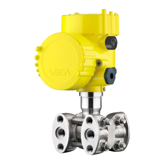
Pressure transmitter with metallic measuring cell
Hide thumbs
Also See for VEGADIF 85:
- Operating instructions manual (96 pages) ,
- Quick setup manual (24 pages) ,
- Operating instructions manual (88 pages)

Related Manuals for Vega VEGADIF 85


Summary of Contents for Vega VEGADIF 85
- Page 1 Operating Instructions Pressure transmitter with metallic measuring cell VEGADIF 85 HART and accumulator pack Document ID: 54674...
-
Page 2: Table Of Contents
Parameter adjustment with PACTware ................52 Saving the parameterisation data ................... 53 Set up with other systems ....................54 DD adjustment programs ....................54 Field Communicator 375, 475 ..................54 Diagnosis, asset management and service ................ 55 VEGADIF 85 • HART and accumulator pack... - Page 3 11.2 Dimensions, versions process component ..............70 11.3 Industrial property rights ....................73 11.4 Trademark ........................73 Safety instructions for Ex areas Take note of the Ex specific safety instructions for Ex applications. These instructions are attached as documents to each instrument with Ex approval and are part of the operating instructions. Editing status: 2019-08-09 VEGADIF 85 • HART and accumulator pack...
-
Page 4: About This Document
Symbols used Document ID This symbol on the front page of this instruction refers to the Docu- ment ID. By entering the Document ID on www.vega.com you will reach the document download. Information, note, tip: This symbol indicates helpful additional infor- mation and tips for successful work. -
Page 5: For Your Safety
During work on and with the device, the required personal protective equipment must always be worn. Appropriate use The VEGADIF 85 is a pressure transmitter for process pressure and hydrostatic level measurement. Due to the integrated accumulator the instrument is particularly suitable as a portable measuring system or test sensor for special applications. -
Page 6: Eu Conformity
Protection of the environment is one of our most important duties. That is why we have introduced an environment management system with the goal of continuously improving company environmental pro- tection. The environment management system is certified according to DIN EN ISO 14001. Please help us fulfil this obligation by observing the environmental instructions in this manual: • Chapter "Packaging, transport and storage" • Chapter "Disposal" VEGADIF 85 • HART and accumulator pack... -
Page 7: Product Description
Scan the Data Matrix code on the type label of the instrument or • Enter the serial number manually in the app Scope of this operating This operating instructions manual applies to the following instrument instructions versions: • Hardware from 1.0.0 • Software from 1.3.4 VEGADIF 85 • HART and accumulator pack... -
Page 8: Principle Of Operation
Typical applications are level meas- urements in pressurized vessels as well as flow measurements in combination with DP flow elements. Further applications are pressure monitoring on filters as well as density and interface measurements. Level measurement The VEGADIF 85 is suitable for level measurement in closed, pressur- ized vessels. The static pressure is compensated via the differential pressure measurement. Fig. 2: Level measurement with VEGADIF 85 in a pressurized vessel Flow measurement The flow measurement is carried out via a DP flow element, such as an orifice or pitot tube. The VEGADIF 85 detects the pressure differ-... - Page 9 3 Product description – Fig. 3: Flow measurement with VEGADIF 85 and orifice, Q = flow, differential pressure Δp = p Differential pressure The pressures in two different pipelines are acquired via effective measurement pressure lines. VEGADIF 85 determines the differential pressure. Fig. 4: Measurement of the differential pressure in pipelines with VEGADIF 85, differential pressure Δp = p...
- Page 10 The instrument can also be used for interface measurement in a ves- sel with changing level. The instrument is connected to the vessel via a chemical seal at two different measuring points. – Fig. 6: Interface measurement with VEGADIF 85 Application area VEGADIF 85 is suitable for applications in virtually all industries. It is used for the measurement of the following pressure types. • Gauge pressure • Absolute pressure •...
-
Page 11: Packaging, Transport And Storage
Protected against solar radiation • Avoiding mechanical shock and vibration • Storage and transport Storage and transport temperature see chapter "Supplement - temperature Technical data - Ambient conditions" • Relative humidity 20 … 85 % VEGADIF 85 • HART and accumulator pack... -
Page 12: Accessories
USB interface of a PC. Protective cover The protective cover protects the sensor housing against soiling and intense heat from solar radiation. Mounting accessories The suitable mounting accessories for VEGADIF 85 include oval flange adapters, valve blocks as well as mounting brackets. VEGADIF 85 • HART and accumulator pack... -
Page 13: Mounting
Tighten the cable gland or plug connector • Lead the connection cable downward in front of the cable entry or plug connector This applies mainly to outdoor installations, in areas where high humidity is expected (e.g. through cleaning processes) and on cooled or heated vessels. Note: Make sure that the degree of contamination specified in chapter "Technical data" meets the existing ambient conditions. VEGADIF 85 • HART and accumulator pack... - Page 14 As soon as the requested posi- tion is reached, tighten the locking screw. DP flow elements are calculated for certain pipeline and operating DP flow element data. Therefore, check the pipeline data before installation at the measuring point and compare the measurement loop number. VEGADIF 85 • HART and accumulator pack...
-
Page 15: Instructions For Oxygen Applications
"Technical data" Danger: Instruments for oxygen applications must be unpacked just before mounting. After removing the protective cover of the process fitting, the label "O " will be visible on the process fitting. Penetration of oil, grease and dirt should be avoided. Danger of explosion! Mounting and connection instructions 3-fold valve block The following illustration shows the connection of a 3-fold valve block. VEGADIF 85 • HART and accumulator pack... - Page 16 Fig. 9: Connection of a 3-fold valve block Process fitting Process fitting Inlet valve Inlet valve Breather valve 3-fold valve block - flang- The following illustration shows the connection of the 3-fold valve ing on both sides block, flanging on both sides. Note: No mounting bracket is required for valve blocks that can be flange- mounted on both sides. The process side of the valve block is mounted directly to a DP flow element, e.g. an orifice plate. VEGADIF 85 • HART and accumulator pack...
- Page 17 4 Mounting Fig. 10: Connection of a 3-fold valve block, flanging on both sides Process fitting Process fitting Inlet valve Inlet valve Breather valve 5-fold valve block The following illustration shows the connection of the 5-fold valve block. VEGADIF 85 • HART and accumulator pack...
- Page 18 Breather valve Inlet valve Valve for checking/ventilating Valve for checking/ventilating Connection high/low When connecting VEGADIF 85 to the measuring point, take note of pressure side the high/low pressure side of the process component. The "H" identifies the high pressure side, the low pressure side due to an "L" on the process component next to the oval flanges. Fig. 12: Marking for high/low pressure side on the process component...
-
Page 19: Measurement Setup Level
Blocking valves VEGADIF 85 Precipitator Drain valves 3-fold valve block • In closed vessels with Mount VEGADIF 85 directly to the vessel • single chemical seal Always connect the low pressure side above the max. level in the vessel • For measurement in products with solid content, such as e.g. dirty liquids, the installation of separators and drain valves is recom- mended. - Page 20 • tive pressure line Always connect the low pressure side above the max. level in the vessel • The condensate vessel ensures a constant pressure on the low pressure side • For measurement in products with solid content, such as e.g. dirty liquids, the installation of separators and drain valves is recom- mended. Debris and sediment can thus be collected and removed. VEGADIF 85 • HART and accumulator pack...
-
Page 21: Measurement Setup, Flow
In gases Fig. 17: Measurement setup with flow measurement of gases, connection via 3-fold valve block, flanging on both sides Orifice or impact pressure probe 3-fold valve block, flanging on both sides VEGADIF 85 VEGADIF 85 • HART and accumulator pack... - Page 22 4 Mounting • In vapours Mount VEGADIF 85 below the measurement loop • Mount condensate vessels at the same height with the discharge socket and at the same distance to VEGADIF 85 • Fill the effective pressure lines to the height of the condensate vessels before setup – Fig. 18: Measurement setup, flow measurement in vapours Condensate vessels Orifice or impact pressure probe Blocking valves...
-
Page 23: Measurement Setup Differential Pressure
Drain valves 3-fold valve block 4.6 Measurement setup differential pressure • In gases and vapours Mount VEGADIF 85 above the measurement loop so that conden- sate can drain off in the process cable. Fig. 20: Measurement setup with differential pressure measurement between two pipelines in gases and vapours Pipelines Blocking valves... - Page 24 Debris and sediment can thus be collected and removed. – Fig. 22: Measurement setup with differential pressure measurement in liquids E.g. filter Blocking valves VEGADIF 85 Precipitator Drain valves 3-fold valve block VEGADIF 85 • HART and accumulator pack...
-
Page 25: Measurement Setup, Density
The ambient temperature should be the same for both capillaries ∆p – Fig. 24: Measurement setup for density measurement Density measurement is only possible when the level remains above the upper measuring point. If the level falls below the upper meas- uring point, the measuring system continues to work with the last density value. This density measurement functions with open as well as closed ves- sels. Make sure that small density changes cause only small changes to the measured differential pressure. VEGADIF 85 • HART and accumulator pack... -
Page 26: Measurement Setup, Interface
The total level must be above the upper measurement point. This density measurement functions with open but also with closed vessel. Example Distance between the two measurement points 0.3 m, min. density 800 kg/m , max. density 1000 kg/m Carry out min. adjustment for the differential pressure which is meas- ured at the height of the interface on the lower measurement point: Δp = ρ • g • h = 800 kg/m • 9.81 m/s • 0.3 m = 2354 Pa = 23.54 mbar Carry out max. adjustment for the differential pressure which is meas- ured at the height of the interface on the upper measurement point: Δp = ρ • g • h = 1000 kg/m • 9.81 m/s • 0.3 m VEGADIF 85 • HART and accumulator pack... - Page 27 4 Mounting = 2943 Pa = 29.43 mbar VEGADIF 85 • HART and accumulator pack...
-
Page 28: Connecting To Power Supply
Supply room (accumulator) Electronics compartment Electronics compartment 4...20mA 6 7 8 Fig. 27: Electronics compartment - double chamber housing Internal connection to the connection compartment Contact pins for the display and adjustment module VEGADIF 85 • HART and accumulator pack... -
Page 29: Switch-On Phase
• 5 = sensor is switched on every 30 minutes for 3 minutes • 6 = sensor is switched on every hour for 3 min. • 7 = sensor is switched on every 6 hours for 3 minutes • 8 = sensor is switched on every 12 hours for 3 minutes • 9 = sensor is switched on every 24 hours for 3 minutes The green LED characterizes the charging process: • LED flashes = Accumulator is charging • LED lights = accumulator is full, battery charger should be unplugged (accumulator life time) After pressing the key or changing the mode the yellow LED shows the accumulator status for approximately 10 s as follows: • LED lights = accumulator is full • LED flashes = accumulator should be charged • LED off = accumulator is empty Switch-on phase The instrument is switched on and off by means of a button outside on the housing. VEGADIF 85 • HART and accumulator pack... - Page 30 Indication of a status message, e.g. "F 105 Determine measured value" on the display Then the actual measured value is output to the signal cable. The value takes into account settings that have already been carried out, e.g. default setting. VEGADIF 85 • HART and accumulator pack...
-
Page 31: Set Up The Sensor With The Display And Adjustment Module
3. Screw housing lid with inspection window tightly back on Disassembly is carried out in reverse order. The display and adjustment module is powered by the sensor, an ad- ditional connection is not necessary. Fig. 30: Installing the display and adjustment module in the electronics compart- ment of the single chamber housing VEGADIF 85 • HART and accumulator pack... -
Page 32: Adjustment System
– Move to the menu overview – Confirm selected menu – Edit parameter – Save value • [->] key: – Change measured value presentation – Select list entry – Select menu items – Select editing position • [+] key: VEGADIF 85 • HART and accumulator pack... -
Page 33: Measured Value Indication
5 s, the display returns to the main menu. The menu language is then switched over to "English". Approx. 60 minutes after the last pressing of a key, an automatic reset to measured value indication is triggered. Any values not confirmed with [OK] will not be saved. Measured value indication Measured value indica- With the [->] key you can move between three different indication tion modes. In the first view, the selected measured value is displayed in large digits. VEGADIF 85 • HART and accumulator pack... -
Page 34: Parameter Adjustment - Quick Setup
[->] or [ESC] keys or automatically after 3 s Note: You can find a description of the individual steps in the quick setup guide of the sensor. You can find "Extended adjustment" in the next sub-chapter. Parameter adjustment - Extended adjustment For technically demanding measuring points, you can carry out extended settings in "Extended adjustment". VEGADIF 85 • HART and accumulator pack... - Page 35 The available digits include: • Letters from A … Z • Numbers from 0 … 9 • Special characters +, -, /, - Application The VEGADIF 85 can be used for flow, differential pressure, density and interface measurement. The default setting is differential pressure measurement. Switchover is carried out in the adjustment menu. VEGADIF 85 • HART and accumulator pack...
- Page 36 [->] key. Position correction The installation position of the instrument can shift the measured value (offset). The position correction function compensates this offset. In the process the current measured value can be accepted automatically. VEGADIF 85 has two separate sensor systems: one sensor for dif- ferential pressure and one sensor for static pressure. The following possibilities thus result for position correction: • Automatic correction for both sensors • Manual correction for differential pressure VEGADIF 85 • HART and accumulator pack...
- Page 37 A superim- posed pressure is detected by the low pressure side and automati- cally compensated. See the following example: – 100% Fig. 34: Parameter adjustment example "Min./max. adjustment, level measure- ment" Min. level = 0 % corresponds to 0.0 mbar Max. level = 100 % corresponds to 490.5 mbar VEGADIF 85 • HART and accumulator pack...
- Page 38 [OK]. 2. Edit the percentage value with [OK] and set the cursor to the requested position with [->]. 3. Set the requested percentage value (e.g. 90 %) with [+] and save with [OK]. The cursor jumps now to the pressure value. 4. Enter the pressure value for the full vessel (e.g. 900 mbar) cor- responding to the percentage value. VEGADIF 85 • HART and accumulator pack...
- Page 39 2. Edit the mbar value with [OK] and set the cursor to the requested position with [->]. 3. Set the requested mbar value with [+] and store with [OK]. The max. adjustment is finished. For an adjustment with pressure, simply enter the actual measured value indicated at the bottom of the display. Zero adjustment differen- Proceed as follows: tial pressure 1. Select the menu item "Setup" with [->] and confirm with [OK]. Now select with [->] the menu item "Zero adjustment" and confirm with [OK]. VEGADIF 85 • HART and accumulator pack...
- Page 40 Select in the menu item "Setup" with [->] "Adjustment" and con- firm with [OK]. Now confirm the menu item "Distance" with [OK]. Edit the sensor distance with [OK] and set the cursor to the requested position with [->]. Set the distance with [+] and save with [OK]. The adjustment of the distance is hence finished. Min. adjustment density Proceed as follows: 1. Select the menu item "Setup" with [->] and confirm with [OK]. Now select with [->] the menu item "Min. adjustment" and confirm with [OK]. VEGADIF 85 • HART and accumulator pack...
- Page 41 Select in the menu item "Setup" with [->] "Adjustment" and con- firm with [OK]. Now confirm the menu item "Distance" with [OK]. Edit the sensor distance with [OK] and set the cursor to the requested position with [->]. Set the distance with [+] and save with [OK]. The adjustment of the distance is hence finished. Min. adjustment interface Proceed as follows: 1. Select the menu item "Setup" with [->] and confirm with [OK]. Now select with [->] the menu item "Min. adjustment" and confirm with [OK]. VEGADIF 85 • HART and accumulator pack...
- Page 42 The setting in the delivery status depends on the sensor type. A linearization is necessary for all applications in which the measured Linearisation process variable does not increase linearly with the measured value. This applies for example to the flow measured via the differential pressure or the vessel volume measured via the level. Correspond- ing linearization curves are preprogrammed for such cases. They represent the correlation between the measured value percentage and process variable. The linearization applies to the measured value indication and the current output. VEGADIF 85 • HART and accumulator pack...
- Page 43 The default setting is min. current 3.8 mA and max. current 20.5 mA. Lock/Unlock adjustment In the menu item "Lock/unlock adjustment" you safeguard the sensor parameters against unauthorized or unintentional modifications. The device assumes an approximately constant temperature and static pressure and calculates the flow rate from the measured differential pressure using the characteristic curve extracted by root. VEGADIF 85 • HART and accumulator pack...
- Page 44 Polish • Czech • Turkish In delivery status, the VEGADIF 85 is set to English. Display value 1 and 2 - In this menu item, you define which measured value is displayed. 4 … 20 mA The default setting for the displayed value is "Differential pressure". Display format 1 and 2 In this menu item you define the number of decimal positions with which the measured value is displayed.
- Page 45 In menu item "Peak value, temperature", both values are displayed. In another window you can carry out a reset of the two peak values separately. Simulation 4 … 20 mA/ In this menu item you can simulate measured values. This allows the HART signal path to be tested, e.g. through downstream indicating instru- ments or the input card of the control system. VEGADIF 85 • HART and accumulator pack...
- Page 46 Basic settings: Resets the parameter settings, incl. special param- eters, to the default values of the respective instrument. Any pro- grammed linearisation curve as well as the measured value memory are deleted. Totalizer 1 and 2: Reset of the summarized flow volumes with ap- plication "Flow" The following table shows the default values of the instrument. De- pending on the instrument version or application, all menu items may not be available or some may be differently assigned: VEGADIF 85 • HART and accumulator pack...
- Page 47 Pressure Actual measured value Temperature Actual temperature values from measuring cell, elec- tronics Simulation Process pressure Additional adjustments Menu item Parameter Default value 0000 Date/Time Actual date/Actual time Copy instrument settings Special parameters No reset VEGADIF 85 • HART and accumulator pack...
- Page 48 0 % and 100 %. Current output 1 and 2 In menu item "Current output, variable" you specify which measured (size) variable is output via the current output. VEGADIF 85 • HART and accumulator pack...
- Page 49 4 … 20 mA signal in Multidrop mode. In the mode "Fixed current (4 mA)" a fixed 4 mA signal is output inde- pendently of the actual level. The setting in the delivery status is "Analogue current output" and the address 00. VEGADIF 85 • HART and accumulator pack...
- Page 50 Instrument version In this menu item, the hardware and software version of the sensor is displayed. Factory calibration date In this menu item, the date of factory calibration of the sensor as well as the date of the last change of sensor parameters are displayed via the display and adjustment module or via the PC. VEGADIF 85 • HART and accumulator pack...
-
Page 51: Saving The Parameterisation Data
In the display and adjust- If the instrument is equipped with a display and adjustment module, ment module the parameter adjustment data can be saved therein. The procedure is described in menu item "Copy device settings". VEGADIF 85 • HART and accumulator pack... -
Page 52: Setup With Pactware
Internet. Further setup steps are described in the operating instructions manu- al "DTM Collection/PACTware" attached to each DTM Collection and which can also be downloaded from the Internet. Detailed descrip- tions are available in the online help of PACTware and the DTMs. VEGADIF 85 • HART and accumulator pack... -
Page 53: Saving The Parameterisation Data
In addition, there is a tank calculation program as well as a multiviewer for display and analysis of the saved measured value and echo curves. The standard version is available as a download under www.vega.com/downloads and "Software". The full version is avail- able on CD from the agency serving you. Saving the parameterisation data We recommend documenting or saving the parameterisation data via PACTware. That way the data are available for multiple use or service... -
Page 54: Set Up With Other Systems
Device descriptions for the instrument are available as EDD for pa- rameterisation with Field Communicator 375 or 475. Integrating the EDD into the Field Communicator 375 or 475 requires the "Easy Upgrade Utility" software, which is available from the manu- facturer. This software is updated via the Internet and new EDDs are automatically accepted into the device catalogue of this software after they are released by the manufacturer. They can then be transferred to a Field Communicator. VEGADIF 85 • HART and accumulator pack... -
Page 55: Diagnosis, Asset Management And Service
When the instrument is shipped, the measured value memory is ac- tive and stores pressure value and measuring cell temperature every 10 s, with electronic differential pressure also the static pressure. The requested values and recording conditions are set via a PC with PACTware/DTM or the control system with EDD. Data are thus read out and also reset. Event memory Up to 500 events are automatically stored with a time stamp in the sensor (non-deletable). Each entry contains date/time, event type, event description and value. Event types are for example: • Modification of a parameter VEGADIF 85 • HART and accumulator pack... -
Page 56: Asset Management Function
This status message is inactive by default. Maintenance: Due to external influences, the instrument function is limited. The measurement is affected, but the measured value is still valid. Plan in maintenance for the instrument because a failure is expected in the near future (e.g. due to buildup). This status message is inactive by default. VEGADIF 85 • HART and accumulator pack... - Page 57 Inconsistent settings (e.g.: dis- Modify settings Bit 12 of tance, adjustment units with Byte 0 … 5 Installation/Setup error Modify connected sensor con- application process pressure) figuration or application for selected application Invalid sensor configuration (e.g.: application electronic differential pressure with con- nected differential pressure measuring cell) VEGADIF 85 • HART and accumulator pack...
- Page 58 Byte 14 … 24 Error in the event mem- Send instrument for repair M504 Hardware defect Exchanging the electronics Bit 3 of Byte 14 … 24 Error at a device in- Send instrument for repair terface VEGADIF 85 • HART and accumulator pack...
-
Page 59: Rectify Faults
"Setup" must be carried out again or must be checked for plausibility and completeness. Should these measures not be successful, please call in urgent cases 24 hour service hotline the VEGA service hotline under the phone no. +49 1805 858550. The hotline is also available outside normal working hours, seven days a week around the clock. Since we offer this service worldwide, the support is provided in English. -
Page 60: Exchanging The Electronics Module
• Attach the completed form and, if need be, also a safety data sheet outside on the packaging • Ask the agency serving you to get the address for the return ship- ment. You can find the agency on our homepage. VEGADIF 85 • HART and accumulator pack... -
Page 61: Dismount
Proceed as follows to dismount the accumulator: • Unscrew the cover of the supply room • Loosen the plug connector • Loosen the fixing screws • Pull out the complete insert by means of the plastic strap If you have no way to dispose of the old instrument properly, please contact us concerning return and disposal. VEGADIF 85 • HART and accumulator pack... -
Page 62: Supplement
Ʋ Screws and nuts for lateral flange PN 160 and PN 400: Hexagon screw DIN 931 M8 x 85 A2-70, hexagon nut DIN 934 M8 A2-70 Ʋ Ground terminal 316Ti/316L Ʋ Connection between IP 68 transmitter PE, PUR and external electronics housing Ʋ Type label support with IP 68 version PE hard on cable Note deviating process temperature limits Glass with Aluminium and stainless steel precision casting housing VEGADIF 85 • HART and accumulator pack... - Page 63 +240 psig Adjustment ranges Maximum permissible Turn Down Unlimited (recommended up to 20 : 1) Adjustment differential pressure Zero/Span adjustment: Ʋ Pressure value zero -120 … +120 % Ʋ Pressure value span Zero + (-240 … +240 %) Adjustment level Min./Max. adjustment: Ʋ Percentage value -10 … +110 % Ʋ Pressure value -120 … +120 % The specifications refer to the nominal measuring range. VEGADIF 85 • HART and accumulator pack...
- Page 64 TD <= 5 : 1 TD > 5 : 1 TD > 10 : 1 10 mbar (1 kPa)/0.145 psi < ±0.02 % x TD < ±0.1 % 30 mbar (3 kPa)/0.44 psi 100 mbar (10 kPa)/1.5 psi < ±0.035 % + 0.01 % x TD 500 mbar (50 kPa)/7.3 psi < ±0.065 % 3 bar (300 kPa)/43.51 psi < ±0.015 % + 0.005 % x TD 16 bar (1600 kPa)/232.1 psi < ±0.035 % + 0.01 % x TD Static pressure VEGADIF 85 • HART and accumulator pack...
- Page 65 Applies also to the analogue 4 … 20 mA current output and refers to the set span. Thermal change, current output < 0.05 %/10 K, max. < 0.15 %, each with -40 … +80 °C (-40 … +176 °F) Measuring range end, absolute pressure Relating to the adjusted span. Relating to the measuring range end value. Measuring range end, absolute pressure. VEGADIF 85 • HART and accumulator pack...
- Page 66 < 0.15 % x TD Static pressure < ±0.065 % < ±0.1 % < ±0.15 % Measuring range end, absolute pressure. Relating to the adjusted span. Relating to the measuring range end value. VEGADIF 85 • HART and accumulator pack...
- Page 67 2320 psig 3481 psig 45 psig 5802 psig 5802 psig 9137 psig 240 psig Mechanical stress Vibration resistance 4 g at 5 … 200 Hz according to EN 60068-2-6 (vibration with resonance) Shock resistance 50 g, 2.3 ms according to EN 60068-2-27 (mechanical shock) Reference temperature +25 °C (+77 °F). 2 g with housing version stainless steel double chamber VEGADIF 85 • HART and accumulator pack...
- Page 68 Selection of the mode Ʋ Button outside on the housing Switching on and off Integrated clock Date format Day.Month.Year Time format 12 h/24 h Time zone, factory setting Max. rate deviation 10.5 min/year External battery charger Mains voltage 100 … 240 V AC IP 66/IP 68 (0.2 bar), only with absolute pressure. VEGADIF 85 • HART and accumulator pack...
- Page 69 IP 66/IP 68 (0.2 bar) Type 6P Stainless steel (electro-polished) Single chamber IP 66/IP 68 (0.2 bar) Type 6P IP 69K Stainless steel (precision cast- Single chamber IP 66/IP 68 (0.2 bar) Type 6P ing) IP 68 (1 bar) Double chamber IP 66/IP 68 (0.2 bar) Type 6P Galvanic separation between electronics and metal housing parts VEGADIF 85 • HART and accumulator pack...
-
Page 70: Dimensions, Versions Process Component
½ NPT Fig. 39: Dimensions of housing - with integrated display and adjustment module the housing is 9 mm/0.35 inches or 18 mm/0.71 in higher Plastic double chamber Aluminium/Stainless steel double chamber When used with fulfilled housing protection. VEGADIF 85 • HART and accumulator pack... - Page 71 11 Supplement Ventilation on process axis 80 mm 54 mm (3.15") (2.13") 86 mm (3.36") Fig. 40: VEGADIF 85, ventilation on process axis Connection Fastening Material Scope of delivery ¼-18 NPT, IEC 61518 7/16-20 UNF 316L incl. 2 vent valves ¼-18 NPT, IEC 61518 7/16-20 UNF Alloy C276 (2.4819)
- Page 72 (2.13") 86,1 mm 86,1 mm (3.39") (3.39") Fig. 42: left: Process fitting VEGADIF 85 prepared for chemical seal assembly. right: Position of the copper ring seal Chemical seal connection Copper ring seal Separating diaphragm VEGADIF 85 • HART and accumulator pack...
-
Page 73: Industrial Property Rights
Les lignes de produits VEGA sont globalement protégées par des droits de propriété intellec- tuelle. Pour plus d'informations, on pourra se référer au site www.vega.com. VEGA lineas de productos están protegidas por los derechos en el campo de la propiedad indus- trial. Para mayor información revise la pagina web www.vega.com. - Page 74 – 3-fold valve block 15, 17 Effective pressure lines 15 – 3-fold valve block, flanging on both sides Electronics compartment 28 Error codes 57, 58 Event memory 55 Fault – Rectification 59 Fault rectification 59 Flow measurement 22 Functional principle 10 HART 49 Interface measurement 26 Level measurement 19, 20 Linearisation 42 VEGADIF 85 • HART and accumulator pack...
- Page 75 Notes VEGADIF 85 • HART and accumulator pack...
- Page 76 Subject to change without prior notice © VEGA Grieshaber KG, Schiltach/Germany 2019 VEGA Grieshaber KG Phone +49 7836 50-0 Am Hohenstein 113...
Need help?
Do you have a question about the VEGADIF 85 and is the answer not in the manual?
Questions and answers