Vega VEGADIF 65 Operating Instructions Manual
Differential pressure transmitter with metallic measuring diaphragm
Hide thumbs
Also See for VEGADIF 65:
- Operating instructions manual (104 pages) ,
- Operating instructions manual (16 pages) ,
- Operating instructions manual (88 pages)

Subscribe to Our Youtube Channel
Related Manuals for Vega VEGADIF 65


Summary of Contents for Vega VEGADIF 65
-
Page 1: Operating Instructions
Operating Instructions Differential pressure transmitter with metallic measuring diaphragm VEGADIF 65 4 … 20 mA Document ID: 36236... -
Page 2: Table Of Contents
Adjustment with the display and adjustment module PLICSCOM Short description ......................42 Insert display and adjustment module ................42 Adjustment system ......................43 Set parameters ....................... 44 6.5 Menu schematic ......................53 6.12 Saving the parameterisation data ................... 56 VEGADIF 65 • 4 … 20 mA... - Page 3 10.1 Technical data ........................ 66 10.2 Dimensions, versions process component ..............77 10.3 Industrial property rights ....................83 Safety instructions for Ex areas Take note of the Ex specific safety instructions for Ex applications. These instructions are attached as documents to each instrument with Ex approval and are part of the operating instructions manual. Editing status: 2017-08-21 VEGADIF 65 • 4 … 20 mA...
-
Page 4: About This Document
List The dot set in front indicates a list with no implied sequence. → Action This arrow indicates a single action. Sequence of actions Numbers set in front indicate successive steps in a procedure. Battery disposal This symbol indicates special information about the disposal of bat- teries and accumulators. VEGADIF 65 • 4 … 20 mA... -
Page 5: For Your Safety
The safety instructions in this operating instructions manual, the na- tional installation standards as well as the valid safety regulations and accident prevention rules must be observed by the user. For safety and warranty reasons, any invasive work on the device beyond that described in the operating instructions manual may be carried out only by personnel authorised by the manufacturer. Arbi- VEGADIF 65 • 4 … 20 mA... -
Page 6: Safety Label On The Instrument
For instruments in oxygen applications the special instructions in chapters "Storage and transport", "Mounting" as well as "Technical data" under "Process conditions"must be noted. Furthermore the valid national regulations, implementation instructions and memorandums of the professional assocations must be noted. VEGADIF 65 • 4 … 20 mA... -
Page 7: Environmental Instructions
Protection of the environment is one of our most important duties. That is why we have introduced an environment management system with the goal of continuously improving company environmental pro- tection. The environment management system is certified according to DIN EN ISO 14001. Please help us fulfil this obligation by observing the environmental instructions in this manual: • Chapter "Packaging, transport and storage" • Chapter "Disposal" VEGADIF 65 • 4 … 20 mA... -
Page 8: Product Description
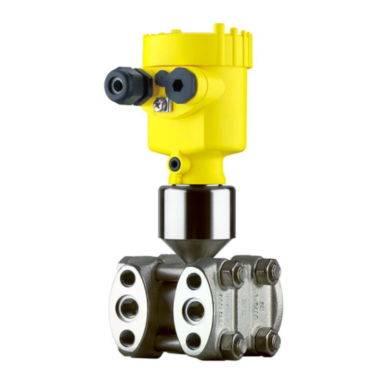
– Ex-specific "Safety instructions" (with Ex versions) – Certificate "For oxygen application" (with respective versions) – If necessary, further certificates Constituent parts The following illustration shows the components of VEGADIF 65: + – Fig. 1: VEGADIF 65 in basic version Housing cover, optionally with integrated display and adjustment module Housing with electronics Process component with measuring cell The components are available in different versions. The type label contains the most important data for identification and use of the instrument: VEGADIF 65 •... -
Page 9: Principle Of Operation
11 Serial number of the instrument 12 ID numbers, instrument documentation With the serial number, you can access the delivery data of the instru- ment via "www.vega.com", "VEGA Tools" and "serial number search". You can find the serial number on the inside of the instrument as well as on the type label on the outside. -
Page 10: Level Measurement
3 Product description Flow measurement – – Fig. 3: Flow measurement with VEGADIF 65 and DP flow element, Q = flow, Δp = differential pressure, Δp = p Orifice Pitot tube Level measurement – – ρ g Fig. 4: Level measurement with VEGADIF 65. Δp = differential pressure, ρ =... - Page 11 Fig. 5: Differential pressure measurement with VEGADIF 65 Filter VEGADIF 65 Density measurement – Fig. 6: Density measurement with VEGADIF 65, h = defined mounting distance, Δp = differential pressure, ρ = density of the medium, g = acceleration of gravity VEGADIF 65 Interface measurement –...
-
Page 12: Adjustment
"Heating for display and adjustment module". This function is generally not available for approved instruments. Adjustment The instrument can be adjusted with the following adjustment media: • With the display and adjustment module • with the suitable VEGA DTM in conjunction with an adjustment software according to the FDT/DTM standard, e.g. PACTware and VEGADIF 65 • 4 … 20 mA... -
Page 13: Packaging, Transport And Storage
You can find further information in the operating instructions "Display and adjustment module PLICSCOM" (Document-ID 27835). The interface adapter VEGACONNECT enables the connection of VEGACONNECT communication-capable instruments to the USB interface of a PC. For parameter adjustment of these instruments, an adjustment software such as PACTware with VEGA DTM is required. VEGADIF 65 • 4 … 20 mA... - Page 14 The protective cover protects the sensor housing against soiling and intense heat from solar radiation. You will find additional information in the supplementary instructions manual "Protective cover" (Document-ID 34296). Oval flange adapter The oval flange adapter enables the connection of a ½ NPT tube to a VEGADIF 65 or a valve block. By selecting the suitable materials, the oval flange adapter can be adapted to all processes. You can find additional information in the supplementary instructions "Mounting accessories, pressure" (Document-ID 43478). Valve blocks Valve blocks enable simple installation and setup of a differential pressure transmitter. When the process valves are closed, the equali-...
- Page 15 3 Product description You find further information in the operating instructions "Electronics module VEGABAR series 50 and 60 " (Document-ID 30175). VEGADIF 65 • 4 … 20 mA...
-
Page 16: Mounting
Fig. 9: Position of the filter element with single and double chamber housing Filter element for ventilation of the electronics housing Blind plug Information: Make sure that the filter element is always free of buildup during op- eration. A high-pressure cleaner may not be used for cleaning. VEGADIF 65 • 4 … 20 mA... -
Page 17: Instructions For Oxygen Applications
"O " will be visible on the process fitting. Penetration of oil, grease and dirt should be avoided. Danger of explosion! Mounting and connection instructions Connection plus/minus When connecting the VEGADIF 65 to the measurement loop, take side note of the plus/minus side of the process component. The plus side is marked with a "+", the minus side with a "-" on the process compo- nent next to the oval flanges. - Page 18 Oval flange adapter Fixing screws 10 Effective pressure line Valve blocks Valve blocks enable the simple installation and setup of the differential pressure transmitter. They separate the pressure transmitter from the process side and enable also a check of the measurement loop. They VEGADIF 65 • 4 … 20 mA...
- Page 19 The 3-fold valve block with flanging on both sides enables a mechani- cally stable connection between the VEGADIF 65 and e.g. the tapping points or the flange plate of a pitot tube. With the five-fold valve block, two additional valves allow blowing out the process lines or checking the VEGADIF 65 in installed condition. 3-fold valve block The following illustration shows the connection of the 3-fold valve block. Fig. 12: Connection of a 3-fold valve block Process fitting Process fitting Inlet valve Inlet valve Breather valve VEGADIF 65 • 4 … 20 mA...
- Page 20 3-fold valve block, flang- ing on both sides block, flanging on both sides. Fig. 13: Connection of a 3-fold valve block, flanging on both sides Process fitting Process fitting Inlet valve Inlet valve Breather valve 5-fold valve block The following illustration shows the connection of the 5-fold valve block. VEGADIF 65 • 4 … 20 mA...
-
Page 21: Measurement Setup - Flow
Fig. 14: Connection of a 5-fold valve block Process fitting Process fitting Check/Ventilate Check/Ventilate Valve for checking/ventilating Valve for checking/ventilating Inlet valve Inlet valve Breather valve Measurement setup - Flow → In gases Mount VEGADIF 65 above the measurement loop so that con- densate can drain off in the process cable. VEGADIF 65 • 4 … 20 mA... - Page 22 3-fold valve block, flanging on both sides VEGADIF 65 3-fold valve block, flanging on both sides Orifice or impact pressure probe In vapours Mount VEGADIF 65 below the measurement loop Mount condensate vessels at the same height with the discharge socket and at the same distance to VEGADIF 65 Fill the effective pressure lines to the height of the condensate vessels before setup VEGADIF 65 • 4 … 20 mA...
- Page 23 3-fold valve block When using a 5-fold valve block, the drain or blow-off valves are already integrated. In liquids Mount VEGADIF 65 below the measurement loop so that the ef- fective pressure lines are always filled with liquid and gas bubbles can bubble up to the process line For measurements in products with solid content such as e.g. dirty liquids, the installation of separators and drain valves is recommended to enable collection and removal of debris and sediment. Fill the effective pressure lines to the height of the condensate vessels before setup VEGADIF 65 • 4 … 20 mA...
-
Page 24: Measurement Setup Level
Fig. 19: Measurement setup, level measurement in the open vessel VEGADIF 65 Minus side is open to the atmospheric pressure Blocking valve Precipitator Drain valve VEGADIF 65 • 4 … 20 mA... - Page 25 – max. min. Fig. 21: Measurement setup, level measurement in closed vessel Blocking valves VEGADIF 65 Precipitator Drain valves 3-fold valve block VEGADIF 65 • 4 … 20 mA...
- Page 26 The ambient temperature should be the same for both capillaries Information: Level measurement is only ensured between the upper edge of the lower and the lower edge of the upper chemical seal. – max. min. Fig. 23: Measurement setup, level measurement in closed vessel VEGADIF 65 In closed vessels with Mount VEGADIF 65 below the lower measurement connection so steam layering with effec- that the effective pressure lines are always filled with liquid tive pressure line Connect minus side always above the max. level VEGADIF 65 • 4 … 20 mA...
- Page 27 In closed vessels with Mount VEGADIF 65 directly to the vessel superimposed steam with Connect minus side always above the max. level single chemical seal The condensate vessel ensures a constant pressure on the minus side For measurements in products with solid content such as e.g. dirty liquids, the installation of separators and drain valves is recommended to enable collection and removal of debris and sediment. VEGADIF 65 • 4 … 20 mA...
-
Page 28: Measurement Setup Density And Interface
The density measurement is carried out in the mode level measure- ment. Mount VEGADIF 65 below the lower chemical seal The ambient temperature should be the same for both capillaries Example for a density measurement: Distance between the two measurement points: 0.3 m Min. density: 1000 kg/m³ Max. density: 1200 kg/m³ Measured differential pressure: Δp = ρ • g • h The min. adjustment is carried out for the differential pressure meas- ured at density 1.0: Δp = ρ • g • h = 1000 kg/m³ • 9.81 m/s • 0,3 m = 2943 Pa = 29.43 mbar VEGADIF 65 • 4 … 20 mA... - Page 29 This density measurement functions with open but also with closed vessel. Example for an interface measurement: Distance between the two measurement points: 0.3 m Min. density: 800 kg/m³ Max. density: 1000 kg/m³ The min. adjustment is carried out for the differential pressure occur- ing with density 0.8: Δp = ρ • g • h = 800 kg/m³ • 9.81 m/s • 0.3 m = 2354 Pa = 23.54 mbar The max. adjustment is carried out for the differential pressure occur- ing with density 1.0: Δp = ρ • g • h = 1000 kg/m³ • 9.81 m/s • 0.3 m = 2943 Pa = 29.43 mbar Mount VEGADIF 65 below the lower chemical seal The ambient temperature should be the same for both capillaries VEGADIF 65 • 4 … 20 mA...
-
Page 30: Measurement Setup Differential Pressure
VEGADIF 65 3-fold valve block Blocking valves Pipelines → In vapour and conden- Mount VEGADIF 65 below the measurement loop so that some sate plants condensate can collect in the effective pressure lines. The ventilation is carried out via the ventilation valves on the instru- ment, the 5-fold valve block enables blowing out the cables. VEGADIF 65 • 4 … 20 mA... - Page 31 For measurements in products with solid content such as e.g. dirty liquids, the installation of separators and drain valves is recommended to enable collection and removal of debris and sediment. – Fig. 30: Measurement setup, flow measurement in liquids E.g. filter Blocking valves VEGADIF 65 Precipitator Drain valves 3-fold valve block VEGADIF 65 • 4 … 20 mA...
-
Page 32: Mounting External Housing
Capillaries E.g. filter VEGADIF 65 Mounting external housing 1. Mark the holes according to the following drilling template 2. Depending on the mounting surface, fasten the wall mounting plate with 4 screws 90 mm (3.54") 8 mm 70 mm (2.76") (0.32") 3 mm (0.12") Fig. 32: Drilling template - wall mounting plate VEGADIF 65 • 4 … 20 mA... -
Page 33: Installation Control
4 Mounting Mount the wall mounting plate so that the cable entry of the socket housing points downward. The socket housing can be displaced by 180° to the wall mounting plate. Installation control Check the following after mounting the instrument: • Did you tighten all screws? • Closing screws and ventilation valves closed VEGADIF 65 • 4 … 20 mA... -
Page 34: Connecting To Power Supply
Take note of safety conformity and type approval certificates of the sensors and power instructions for Ex supply units. applications Voltage supply Power supply and current signal are carried on the same two-wire cable. The voltage supply range can differ depending on the instru- ment version. The data for power supply are specified in chapter "Technical data". Provide a reliable separation between the supply circuit and the mains circuits according to DIN EN 61140 VDE 0140-1. The VEGA power supply units VEGATRENN 149AEx, VEGASTAB 690, VEGADIS 371 as well as all VEGAMETs meet this requirement. Keep in mind the following additional influences on the operating voltage: • Output voltage of the power supply unit can be lower under nomi- nal load (with a sensor current of 20.5 mA or 22 mA in case of fault message) • Influence of additional instruments in the circuit (see load values in chapter "Technical data") -
Page 35: Connection Procedure
10. Connect the screen to the internal ground terminal, connect the external ground terminal to potential equalisation 11. Tighten the compression nut of the cable entry gland. The seal ring must completely encircle the cable 12. Screw the housing lid back on The electrical connection is finished. VEGADIF 65 • 4 … 20 mA... -
Page 36: Single Chamber Housing
Fig. 33: Connection steps 6 and 7 Single chamber housing Electronics and terminal compartment 4...20mA Display Fig. 34: Electronics and terminal compartment - single chamber housing Spring-loaded terminals for voltage supply Ground terminal for connection of the cable screen VEGADIF 65 • 4 … 20 mA... -
Page 37: Double Chamber Housing
Double chamber housing Terminal compartment I 2 C Fig. 36: Terminal compartment - double chamber housing Spring-loaded terminals for voltage supply Plug connector for VEGACONNECT (I²C interface) Ground terminal for connection of the cable screen VEGADIF 65 • 4 … 20 mA... -
Page 38: Double Chamber Housing Ex D Ia
I ² C 5 6 7 8 Fig. 38: Electronics compartment, double chamber housing Plug connector for service Internal connection cable to the connection compartment Terminals for the external display and adjustment unit VEGADIF 65 • 4 … 20 mA... -
Page 39: Version Ip 66/Ip 68, 1 Bar
Pin 4 Black Version IP 66/IP 68, 1 bar Wire assignment, con- nection cable Fig. 41: Wire assignment, connection cable Brown (+) and blue (-) to power supply or to the processing system Shielding VEGADIF 65 • 4 … 20 mA... -
Page 40: External Housing On Ip 68 Version
Ground terminal for connection of the cable screen Cable gland to the sensor Terminal compartment for sensor connection 1 2 3 4 Fig. 43: Connection of the sensor in the housing base Brown Blue Yellow White Shielding VEGADIF 65 • 4 … 20 mA... -
Page 41: Switch-On Phase
30 seconds: • Internal check of the electronics • Indication of the instrument type, the firmware as well as the sen- sor TAGs (sensor designation) • Output signal jumps briefly (approx. 10 seconds) to the set fault current Then the corresponding current is outputted to the cable (the value corresponds to the actual level as well as the settings already carried out, e.g. factory setting). VEGADIF 65 • 4 … 20 mA... -
Page 42: Adjustment With The Display And Adjustment Module Plicscom
3. Press the display and adjustment module onto the electronics and turn it to the right until it snaps in 4. Screw housing lid with inspection window tightly back on Disassembly is carried out in reverse order. The display and adjustment module is powered by the sensor, an ad- ditional connection is not necessary. VEGADIF 65 • 4 … 20 mA... -
Page 43: Adjustment System
Fig. 45: Insert display and adjustment module Note: If you intend to retrofit the instrument with a display and adjustment module for continuous measured value indication, a higher lid with an inspection glass is required. Adjustment system Fig. 46: Display and adjustment elements LC display Indication of the menu item number Adjustment keys • [OK] key: Key functions VEGADIF 65 • 4 … 20 mA... -
Page 44: Set Parameters
Basic adjustmen - Ap- The VEGADIF 65 can be used for differential pressure, level, flow plication as well as density and interface measurement. The selection of the respective application is carried out in the menu item "Application". Dependent on the selected application, the adjustment is carried out as zero/span or min./max. adjustment. VEGADIF 65 • 4 … 20 mA... - Page 45 2. Confirm the menu "Basic adjustment" with [OK], the menu item "Unit" will be displayed. Unit Unit of measurement ▼ mbar Temperature unit ▼ °C 3. Activate the selection with [OK] and select "Units of measure- ment with [->]. 4. Activate the selection with [OK] and select the requested unit with [->] (in the example bar). 5. Confirm with [OK] and move to position correction with [->]. VEGADIF 65 • 4 … 20 mA...
- Page 46 In this menu item, the offset value as well as the current measured value are displayed. Proceed as follows: 1. Activate in the menu item "Position correction" the selection with [OK]. Position correction Offset 0.0000 bar 0.0035 bar 2. Select with [->], e.g. to accept the actual measured value 0.0035 bar. VEGADIF 65 • 4 … 20 mA...
- Page 47 1. Edit the bar value in the menu item "span" with [OK]. Span adjustment 100.00 % 0.5000 bar 0.0000 bar Information: If the instrument has not yet been adjusted, the displayed pressure for 100 % corresponds to the nominal measuring range of the sensor (in the above example 500 mbar). VEGADIF 65 • 4 … 20 mA...
- Page 48 The max. adjustment is finished. Basic adjustment - Min. For the min. adjustment with density, a filling of the vessel is not adjustment with density necessary. The numeric examples are stated in chapter Mounting, Measurement setup, Density and interface of this instructions manual. Proceed as follows: 1. Edit the % value in the menu item "Min. adjustment" with [OK]. VEGADIF 65 • 4 … 20 mA...
- Page 49 1. Edit the bar value in the menu item "Min. adjustment" with [OK]. Min. adjustment 0.00 % 0.0000 bar 0.0000 bar 2. Set the requested bar value with [+] and [->]. 3. Confirm with [+] and move to max. adjustment with [->]. For an adjustment with flow, simply enter the actual measured value indicated at the bottom of the display. VEGADIF 65 • 4 … 20 mA...
- Page 50 By activating the suitable curve, the percentage vessel volume is displayed correctly. Linearisation curve Linear Enter the requested parameters via the appropriate keys, save your settings and jump to the next menu item with the [->] key. Caution: Note the following if the VEGADIF 65 with corresponding approval is used as part of an overfill protection system according to WHG (Water Resources Act): If a linearisation curve is selected, the measuring signal is no longer necessarily linear to the filling height. This must be considered by the VEGADIF 65 • 4 … 20 mA...
- Page 51 Part sum counter 0 % = +0000 100 % = +0000 6. Edit with [OK] and set the requested values with [+] and [->]. 7. Confirm with [OK] and jump back to the indication of the part sum counter. 8. Select with [->] the unit of the sum counter, adjust the requested unit with [->], for example m /s and confirm with [OK]. VEGADIF 65 • 4 … 20 mA...
- Page 52 The reset "Basic adjustment" resets the values of the following menu items to the reset values (see table): Menu section Menu item Reset value Basic settings Zero/Min. adjustment Measuring range begin Span/Max. adjustment Measuring range end Density 1 kg/l Density unit kg/l Damping Linearisation Linear Sensor-TAG Sensor VEGADIF 65 • 4 … 20 mA...
-
Page 53: Menu Schematic
Additional adjustment and diagnosis options such as e.g. scaling, simulation or trend curve presentation are shown in the following menu schematic. You will find a detailed description of these menu items in the operating instructions manual "Display and adjustment module". Menu schematic Information: Depending on the version and application, the highlighted menu windows may not always be available. VEGADIF 65 • 4 … 20 mA... - Page 54 Temperature unit ▼ 0.0000 bar 0.0000 bar °C Max. adjustment Damping Linearisation curve Creeping distance suppres. ▶ 100.00 % Linear Extracted by root ▼ Activated 0.5000 bar Bidirectionally linear ▼ 0.0000 bar Sensor-TAG Sensor VEGADIF 65 • 4 … 20 mA...
- Page 55 Info Peak value indicator Sensor status Trend curve Totalizer p-min.: -5.8 mbar 0.0000 10 p-max.: 167.5 mbar Start trend curve? T-min.: -12.5 °C T-max.: +85.5 °C Modify settings? Part sum counter 0.0000 10 Modify settings? VEGADIF 65 • 4 … 20 mA...
-
Page 56: Saving The Parameterisation Data
"Copy sensor data". The data remain there permanently even if the sensor power supply fails. If it is necessary to exchange the sensor, the display and adjustment module is inserted into the replacement instrument and the data are written into the sensor under the menu item "Copy sensor data". VEGADIF 65 • 4 … 20 mA... -
Page 57: Setup
Fig. 47: Prefered measurement setup for gases, connection via 3-fold valve block, flanging on both sides VEGADIF 65 3-fold valve block 2, 4 Inlet valves Breather valve 6, 7 Vent valves on VEGADIF 65 VEGADIF 65 • 4 … 20 mA... - Page 58 Fig. 48: Preferred measurement setup for liquids VEGADIF 65 3-fold valve block III Precipitator 1, 5 Drain valves 2, 4 Inlet valves Breather valve 6, 7 Vent valves on VEGADIF 65 A, B Blocking valves Proceed as follows: 1. Close valve 3 2. Fill measuring system with medium. For this purpose, open valves A, B (if available) as well as 2, 4: Medium flows in If necessary, clean the differential pressure lines: - with gases by blowing out with compressed air - with liquids by rinsing.
-
Page 59: Level Measurement
Fig. 49: Preferred measurement setup for closed vessels VEGADIF 65 3-fold valve block III Precipitator 1, 5 Drain valves 2, 4 Inlet valves 6, 7 Vent valves on VEGADIF 65 A, B Blocking valves Proceed as follows: 1. Fill the vessel to just above the lower tap 2. Fill measuring system with medium Close valve 3: Separate high/low pressure side Valves 1, 3, 5: Configuration with 5 valves. - Page 60 3-fold valve block III Precipitator IV Condensate vessel 1, 5 Drain valves 2, 4 Inlet valves Breather valve 6, 7 Vent valves on VEGADIF 65 A, B Blocking valves Proceed as follows: 1. Fill the vessel to just above the lower tap 2. Fill measuring system with medium Open valve A and B: Open block valves...
-
Page 61: Density And Interface Measurement
Valve 3, 6 and 7 are closed Valves 2, 4, A and B are open. Density and interface measurement For density and interface measurements, VEGADIF 65 with double chemical seal is used. VEGADIF 65 in this version is immediately ready for operation. 7.5 Differential pressure measurement Instructions For differential pressure measurements, VEGADIF 65 without chemi- cal seal or with double chemical seal is used. VEGADIF 65 with double chemical seal is immediately ready for operation. -
Page 62: Maintenance And Fault Rectification
24 hour service hotline Should these measures not be successful, please call in urgent cases the VEGA service hotline under the phone no. +49 1805 858550. The hotline is manned 7 days a week round-the-clock. Since we offer this service worldwide, the support is only available in the English language. The service is free, only standard call charges are incurred. -
Page 63: Exchanging The Electronics Module
Software update The following components are required to update the instrument software: • Instrument • Voltage supply • Interface adapter VEGACONNECT • PC with PACTware • Current instrument software as file You can find the current instrument software as well as detailed information on the procedure in the download area of our homepage: www.vega.com. Fault message can also appear if the pressure is higher than the nominal range. VEGADIF 65 • 4 … 20 mA... -
Page 64: How To Proceed If A Repair Is Necessary
Clean the instrument and pack it damage-proof • Attach the completed form and, if need be, also a safety data sheet outside on the packaging • Please contact the agency serving you to get the address for the return shipment. You can find the agency on our home page www.vega.com. VEGADIF 65 • 4 … 20 mA... -
Page 65: Dismount
These may be used only for privately used products according to the WEEE directive. Correct disposal avoids negative effects on humans and the environ- ment and ensures recycling of useful raw materials. Materials: see chapter "Technical data" If you have no way to dispose of the old instrument properly, please contact us concerning return and disposal. VEGADIF 65 • 4 … 20 mA... -
Page 66: Supplement
Ʋ Inspection window in housing lid for Polycarbonate (UL-746-C listed) display and adjustment module Ʋ Screws and nuts for lateral flange PN 160: Hexagon screw DIN 931 M12 x 90 A4 70, hexa- gon nut DIN 934 M12 A4 70 PN 420: Hexagon screw ISO 4014 M12 x 90 A4, hexa- gon nut ISO 4032 M12 A4 bs Ʋ Ground terminal 316Ti/316L Ʋ Connection between IP 68 transmitter and external electronics housing Ʋ Type label support with IP 68 version PE hard on cable Not with vacuum and absolute pressure measuring ranges < 1 bar VEGADIF 65 • 4 … 20 mA... - Page 67 Basic version 100 mbar 100 ms 180 ms Basic version 500 mbar 100 ms 180 ms Basic version, 3 bar 100 ms 180 ms Basic version 16 bar and 40 bar 100 ms 180 ms VEGADIF 65 • 4 … 20 mA...
- Page 68 Limit point adjustment according to IEC 61298-2 Characteristic curve Linear Values less than -1 bar cannot be set. Values less than -1 bar cannot be set. Values less than -1 bar cannot be set. VEGADIF 65 • 4 … 20 mA...
- Page 69 100 mbar measuring cell Ʋ Turn down 1 : 1 to 4 : 1 ±0.075 % of the set span + influence of the chemical seal Ʋ Turn down > 4 : 1 ±(0.012 x TD + 0.027) % of the set span + influence of the chemical seal Measuring cells ≥ 500 mbar Ʋ Turn down 1 : 1 to 15 : 1 ±0.075 % of the set span + influence of the chemical seal Ʋ Turn down > 15 : 1 ±(0.0015 % x TD + 0.053 %) of the set span + influence of the chemical seal Max. value with horizontal process component. Specification applies to the basic version without chemical seal. The value doubles with instruments with inert oil. Incl. non-linearity, hysteresis and non-repeatability. VEGADIF 65 • 4 … 20 mA...
- Page 70 URL/7 bar URL/70 bar URL/70 bar URL/70 bar zero point Influence of the sys- ±0.035 % of ±0.14 % of ±0.14 % of ±0.14 % of tem pressure to the URL/7 bar URL/70 bar URL/70 bar URL/70 bar span Measuring cell 3 bar 16 bar 40 bar Influence of the system ±0.075 % of URL/7 bar ±0.075 % of URL/70 bar ±0.075 % of URL/70 bar pressure to the zero point VEGADIF 65 • 4 … 20 mA...
- Page 71 (+50 … +140 °F). Diaphragm ma- Turn Down up to 316L, Alloy Alloy gold rhodium Tantalum terial Measuring cell 10 mbar 1 : 1 < ±0.35 % < ±0.64 % < ±0.61 % 30 mbar 1 : 1 < ±0.77 % < ±0.99 % < ±1.66 % VEGADIF 65 • 4 … 20 mA...
-
Page 72: Ambient Conditions
Ʋ Versions IP 66/IP 68 (1 bar) and IP 68, -20 … +80 °C (-4 … +176 °F) connection cable PUR Process conditions The pressure and temperature specifications are used as overview. In general, the max. pressure for the pressure transmitter depends on the weakest (with regard to pressure) link. In detail, the respective specifications of the type label apply. Process temperature limits Up to 60 °C (140 °F). VEGADIF 65 • 4 … 20 mA... - Page 73 160 bar (16000 kPa) 160 bar (16000 kPa) 240 bar (24000 kPa) 420 bar (42000 kPa) 420 bar (42000 kPa) 630 bar (63000 kPa) For the version for oxygen application, note chapter "Oxygen applications". Reference temperature +20 °C (+68 °F) VEGADIF 65 • 4 … 20 mA...
- Page 74 Ʋ Configuration four wires, one suspension wire, one breather capillary, screen braiding, metal foil, mantle Ʋ Wire cross-section 0.5 mm² (AWG 20) Reference temperature +20 °C (+68 °F) Tested according to the guidelines of German Lloyd, GL directive 2. Tested according to EN 60068-2-27. Depending on the version M12 x 1, according to ISO 4400, Harting, 7/8" FF. VEGADIF 65 • 4 … 20 mA...
- Page 75 Protection rating Ʋ unassembled IP 20 Ʋ mounted into the sensor without cover IP 40 Ambient temperature - Display and -20 … +70 °C (-4 … +158 °F) adjustment module Material Ʋ Housing Ʋ Inspection window Polyester foil Depending on the version M12 x 1, according to ISO 4400, Harting, 7/8" FF. VEGADIF 65 • 4 … 20 mA...
- Page 76 Ʋ External housing IP 65 Overvoltage category For voltage supply via separator through networks of overvoltage category III Protection class Approvals Instruments with approvals can have different technical specifications depending on the version. For that reason the associated approval documents of these instruments have to be carefully noted. They are part of the delivery or can be downloaded under www.vega.com "Instrument search (serial number)" as well as in the general download area. VEGADIF 65 • 4 … 20 mA...
-
Page 77: Dimensions, Versions Process Component
Double chamber version Aluminium housing ~ 116 mm ~ 87 mm (3.43") (4.57") ø 86 mm ø 86 mm (3.39") (3.39") M16x1,5 M20x1,5 M20x1,5/ ½ NPT M20x1,5/ ½ NPT Single chamber version Double chamber version VEGADIF 65 • 4 … 20 mA... - Page 78 ~ 105 mm (4.13") ø 84 mm (3.31") M16x1,5 M20x1,5/ ½ NPT Single chamber version, Aluminium Single chamber version, stainless steel electropolished Single chamber version, stainless steel precision casting Double chamber housing, aluminium/stainless steel precision casting VEGADIF 65 • 4 … 20 mA...
- Page 79 110 mm x 90 mm (4.33" x 3.54") Fig. 57: External housing Lateral cable outlet Axial cable outlet Plastic version Stainless steel version Seal 2 mm (0.079 in) - only with 3A approval VEGADIF 65 • 4 … 20 mA...
- Page 80 + – 1/4-18 NPT RC1/4 54 mm 100 mm (2.13") (3.94") 98 mm (3.94") Fig. 58: VEGADIF 65 - Connection ¼-18 NPT or RC ¼ Version Connection Fastening Material Scope of delivery 1/4-18 NPT 7/16-20 UNF Steel C 22.8 incl. 2 vent valves IEC 61518 (1.0460)
- Page 81 1/4-18 NPT RC1/4 54 mm 100 mm (2.13") (3.94") 98 mm (3.94") Fig. 59: VEGADIF 65 - Connection ¼-18 NPT or RC ¼, with lateral ventilation Version Connection Fastening Material Scope of delivery 1/4-18 NPT 7/16-20 UNF Steel C 22.8 incl. 4 closing screws...
- Page 82 (2.13") 98 mm 98 mm (3.94") (3.94") Fig. 60: left: Process fitting VEGADIF 65 prepared for chemical seal assembly. right: Position of the copper ring seal Chemical seal connection Copper ring seal Cup diaphragm VEGADIF 65 • 4 … 20 mA...
-
Page 83: Industrial Property Rights
Les lignes de produits VEGA sont globalement protégées par des droits de propriété intellec- tuelle. Pour plus d'informations, on pourra se référer au site www.vega.com. VEGA lineas de productos están protegidas por los derechos en el campo de la propiedad indus- trial. Para mayor información revise la pagina web www.vega.com. - Page 84 Subject to change without prior notice © VEGA Grieshaber KG, Schiltach/Germany 2017 VEGA Grieshaber KG Phone +49 7836 50-0 Am Hohenstein 113...
Need help?
Do you have a question about the VEGADIF 65 and is the answer not in the manual?
Questions and answers