Vega VEGADIF 65 Operating Instructions Manual
4 ... 20 ma differential pressure transmitter with metallic measuring diaphragm
Hide thumbs
Also See for VEGADIF 65:
- Operating instructions manual (104 pages) ,
- Operating instructions manual (36 pages) ,
- Operating instructions manual (92 pages)
Table of Contents
Advertisement
Quick Links
Advertisement
Table of Contents

Subscribe to Our Youtube Channel
Related Manuals for Vega VEGADIF 65


Summary of Contents for Vega VEGADIF 65
-
Page 1: Operating Instructions
Tel: +44 (0)191 490 1547 Fax: +44 (0)191 477 5371 Email: northernsales@thorneandderrick.co.uk Website: www.heattracing.co.uk www.thorneanderrick.co.uk Operating Instructions Differential pressure transmitter with metallic measuring diaphragm VEGADIF 65 4 … 20 mA Document ID: 36236... -
Page 2: Table Of Contents
Insert display and adjustment module ................39 Adjustment system ......................40 Set parameters ....................... 41 6.5 Menu schematic ......................50 6.12 Saving the parameter adjustment data ................53 Setup Select the mode ......................54 VEGADIF 65 • 4 … 20 mA... - Page 3 10 Supplement 10.1 Technical data ........................ 68 10.2 Dimensions ........................79 Safety instructions for Ex areas Please note the Ex-specific safety information for installation and op- eration in Ex areas. These safety instructions are part of the operating instructions manual and come with the Ex-approved instruments. Editing status: 2013-04-10 VEGADIF 65 • 4 … 20 mA...
-
Page 4: About This Document
This symbol indicates special instructions for Ex applications. • List The dot set in front indicates a list with no implied sequence. → Action This arrow indicates a single action. Sequence Numbers set in front indicate successive steps in a procedure. Battery disposal This symbol indicates special information about the disposal of bat- teries and accumulators. VEGADIF 65 • 4 … 20 mA... -
Page 5: For Your Safety
During the entire duration of use, the user is obliged to determine the compliance of the necessary occupational safety measures with the current valid rules and regulations and also take note of new regula- tions. Safety label on the instrument The safety approval markings and safety tips on the device must be observed. VEGADIF 65 • 4 … 20 mA... -
Page 6: Ce Conformity
Protection of the environment is one of our most important duties. That is why we have introduced an environment management system with the goal of continuously improving company environmental pro- tection. The environment management system is certified according to DIN EN ISO 14001. Please help us fulfill this obligation by observing the environmental instructions in this manual: • Chapter "Packaging, transport and storage" • Chapter "Disposal" VEGADIF 65 • 4 … 20 mA... -
Page 7: Product Description
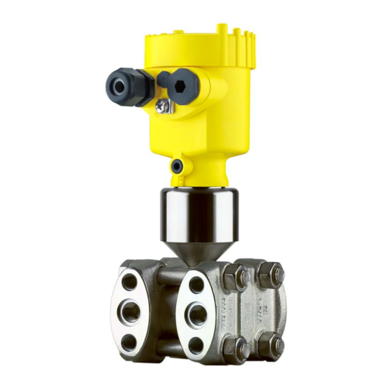
– Ex-specific "Safety instructions" (with Ex versions) – Certificate "For oxygen application" (with respective versions) – if necessary, further certificates Constituent parts The following illustration shows the components of VEGADIF 65: + – Fig. 1: VEGADIF 65 in basic version Housing cover, optionally with integrated display and adjustment module Housing with electronics Process component with measuring cell The components are available in different versions. The nameplate contains the most important data for identification and use of the instrument: VEGADIF 65 •... -
Page 8: Principle Of Operation
11 Serial number of the instrument 12 ID numbers, instrument documentation With the serial number, you can access the delivery data of the instru- ment via www.vega.com, "VEGA Tools" and "serial number search". In addition to the type label outside, you can also find the serial num- ber on the inside of the instrument. -
Page 9: Level Measurement
3 Product description Flow measurement – – Fig. 3: Flow measurement with VEGADIF 65 and DP flow element, Q = flow, Δp = differential pressure, Δp = p Orifice Pitot tube Level measurement – – ρ g Fig. 4: Level measurement with VEGADIF 65. Δp = differential pressure, ρ =... - Page 10 Fig. 5: Differential pressure measurement with VEGADIF 65 Filter VEGADIF 65 Density measurement – Fig. 6: Density measurement with VEGADIF 65, h = defined mounting distance, Δp = differential pressure, ρ = density of the medium, g = acceleration of gravity VEGADIF 65 Interface measurement –...
- Page 11 Measuring element Overload diaphragm/Middle diaphragm Filling oil Separating diaphragm Voltage supply 4 … 20 mA two-wire electronics for voltage supply and measured value transmission on the same cable. The supply voltage range can differ depending on the instrument ver- sion. The exact range is stated in chapter "Technical data". The backlight of the display and adjustment module is powered by the sensor. The prerequisite for this is a supply voltage at a certain VEGADIF 65 • 4 … 20 mA...
-
Page 12: Operation
Not exposed to corrosive media • Protected against solar radiation • Avoiding mechanical shock and vibration • Storage and transport Storage and transport temperature see chapter "Supplement - temperature Technical data - Ambient conditions" • Relative humidity 20 … 85 % VEGADIF 65 • 4 … 20 mA... -
Page 13: Accessories And Replacement Parts
The protective cover protects the sensor housing against soiling and intense heat from solar radiation. You will find additional information in the supplementary instructions manual "Protective cover" (Document-ID 34296). Oval flange adapter The oval flange adapter enables the connection of a ½ NPT tube to a VEGADIF 65 or a valve block. By selecting the suitable materials, the oval flange adapter can be adapted to all processes. You can find additional information in the supplementary instructions "Mounting accessory pressure" (Document-ID 43478). Valve blocks Valve blocks enable simple installation and setup of a differential pressure transmitter. When the process valves are closed, the equali-... - Page 14 You can find additional information in the operating instructions "Chemical seal CSS or CSB" (Document-ID 36133 or 36134). Electronics module The electronics module is a replacement part for pressure transmitter VEGABAR. One version is available for each type of signal output. You find further information in the operating instructions "Electronics module VEGABAR series 50 and 60 " (Document-ID 30175). VEGADIF 65 • 4 … 20 mA...
-
Page 15: Mounting
Information: Make sure that the filter element is always free of buildup during operation. A high-pressure cleaner may not be used for cleaning. Effective pressure trans- DP flow elements are calculated for certain pipeline and operating mitter data. Therefore, check the pipeline data before installation at the measuring point and compare the measurement loop number. VEGADIF 65 • 4 … 20 mA... -
Page 16: Instructions For Oxygen Applications
"O " will be visible on the process fitting. Penetration of oil, grease and dirt should be avoided. Danger of explosion! Mounting and connection instructions Connection plus/minus When connecting the VEGADIF 65 to the measurement loop, take side note of the plus/minus side of the process component. The plus side is marked with a "+", the minus side with a "-" on the process compo- nent next to the oval flanges. - Page 17 Oval flange adapter Fixing screws 10 Effective pressure line Valve blocks enable the simple installation and setup of the differential Valve blocks pressure transmitter. They separate the pressure transmitter from the process side and enable also a check of the measurement loop. They are available as 3-fold and 5-fold version. The integrated equalization valve enables a pressure compensation between plus and minus side VEGADIF 65 • 4 … 20 mA...
- Page 18 VEGADIF 65 in installed condition. Connect 3-fold valve The following illustration shows the connection of the 3-fold valve block block. Fig. 13: Connection of a 3-fold valve block Process fitting Process fitting Inlet valve Inlet valve Breather valve 3-fold valve block, flang- The following illustration shows the connection of the 3-fold valve ing on both sides block, flanging on both sides. VEGADIF 65 • 4 … 20 mA...
- Page 19 4 Mounting Fig. 14: Connection of a 3-fold valve block, flanging on both sides Process fitting Process fitting Inlet valve Inlet valve Breather valve 5-fold valve block The following illustration shows the connection of the 5-fold valve block. VEGADIF 65 • 4 … 20 mA...
-
Page 20: Measurement Setup Flow
Fig. 15: Connection of a 5-fold valve block Process fitting Process fitting Check/Ventilate Check/Ventilate Valve for checking/ventilating Valve for checking/ventilating Inlet valve Inlet valve Breather valve 4.4 Measurement setup flow → In gases Mount VEGADIF 65 above the measurement loop so that con- densate can drain off in the process cable. VEGADIF 65 • 4 … 20 mA... - Page 21 VEGADIF 65 3-fold valve block, flanging on both sides Orifice or impact pressure probe In vapours 1. Mount VEGADIF 65 below the measurement loop 2. Mount condensate vessels at the same height with the discharge socket and at the same distance to VEGADIF 65 3. Fill the effective pressure lines to the height of the condensate vessels before setup VEGADIF 65 • 4 … 20 mA...
- Page 22 When using a 5-fold valve block, the drain or blow-off valves are already integrated. In liquids 1. Mount VEGADIF 65 below the measurement loop so that the ef- fective pressure lines are always filled with liquid and gas bubbles can bubble up to the process line 2. For measurements in products with solid content such as e.g. dirty liquids, the installation of separators and drain valves is recommended to enable collection and removal of debris and sediment. 3. Fill the effective pressure lines to the height of the condensate vessels before setup VEGADIF 65 • 4 … 20 mA...
-
Page 23: Measurement Setup Level
Fig. 20: Measurement setup, level measurement in the open vessel VEGADIF 65 Minus side is open to the atmospheric pressure Blocking valve Separator Drain valve VEGADIF 65 • 4 … 20 mA... - Page 24 – max. min. Fig. 22: Measurement setup, level measurement in closed vessel Blocking valves VEGADIF 65 Separator Drain valves 3-fold valve block VEGADIF 65 • 4 … 20 mA...
- Page 25 Fig. 24: Measurement setup, level measurement in closed vessel VEGADIF 65 In closed vessels with 1. Mount VEGADIF 65 below the lower measurement connection so steam layering with effec- that the effective pressure lines are always filled with liquid tive pressure line 2. Connect minus side always above the max. level 3. The condensate vessel ensures a constant pressure on the minus side VEGADIF 65 • 4 … 20 mA...
- Page 26 2. Connect minus side always above the max. level single chemical seal 3. The condensate vessel ensures a constant pressure on the minus side 4. For measurements in products with solid content such as e.g. dirty liquids, the installation of separators and drain valves is recommended to enable collection and removal of debris and sediment. VEGADIF 65 • 4 … 20 mA...
-
Page 27: Measurement Setup Density And Interface
1. Mount VEGADIF 65 below the lower chemical seal 2. The ambient temperature should be the same for both capillaries Example for a density measurement: Distance between the two measurement points: 0.3 m Min. density: 1000 kg/m³ Max. density: 1200 kg/m³ Measured differential pressure: Δp = ρ • g • h The min. adjustment is carried out for the differential pressure meas- ured at density 1.0: Δp = ρ • g • h = 1000 kg/m³ • 9.81 m/s • 0,3 m = 2943 Pa = 29.43 mbar VEGADIF 65 • 4 … 20 mA... - Page 28 This density measurement functions with open but also with closed vessel. Example for an interface measurement: Distance between the two measurement points: 0.3 m Min. density: 800 kg/m³ Max. density: 1000 kg/m³ The min. adjustment is carried out for the differential pressure occur- ing with density 0.8: Δp = ρ • g • h = 800 kg/m³ • 9.81 m/s • 0.3 m = 2354 Pa = 23.54 mbar The max. adjustment is carried out for the differential pressure occur- ing with density 1.0: Δp = ρ • g • h = 1000 kg/m³ • 9.81 m/s • 0.3 m = 2943 Pa = 29.43 mbar 3. Mount VEGADIF 65 below the lower chemical seal 4. The ambient temperature should be the same for both capillaries VEGADIF 65 • 4 … 20 mA...
-
Page 29: Measurement Setup Differential Pressure
VEGADIF 65 3-fold valve block Blocking valves Pipelines → In vapour and conden- Mount VEGADIF 65 below the measurement loop so that some sate plants condensate can collect in the effective pressure lines. The ventilation is carried out via the ventilation valves on the instru- ment, the 5-fold valve block enables blowing out the cables. VEGADIF 65 • 4 … 20 mA... - Page 30 2. For measurements in products with solid content such as e.g. dirty liquids, the installation of separators and drain valves is recommended to enable collection and removal of debris and sediment. – Fig. 31: Measurement setup, flow measurement in liquids E.g. filter Blocking valves VEGADIF 65 Separator Drain valves 3-fold valve block VEGADIF 65 • 4 … 20 mA...
-
Page 31: Mounting External Housing
Capillaries E.g. filter VEGADIF 65 Mounting external housing 1. Mark the holes according to the following drilling template 2. Depending on the mounting surface, fasten the wall mounting plate with 4 screws 90 mm (3.54") 8 mm 70 mm (2.76") (0.32") 3 mm (0.12") Fig. 33: Drilling template - wall mounting plate VEGADIF 65 • 4 … 20 mA... -
Page 32: Installation Control
4 Mounting Mount the wall mounting plate so that the cable entry of the socket housing points downward. The socket housing can be displaced by 180° to the wall mounting plate. Installation control Check the following after mounting the instrument: • Did you tighten all screws? • Closing screws and ventilation valves closed VEGADIF 65 • 4 … 20 mA... -
Page 33: Connecting To Power Supply
Take note of safety conformity and type approval certificates of the sensors and power instructions for Ex supply units. applications Power supply and current signal are carried on the same two-wire Voltage supply cable. The voltage supply range can differ depending on the instru- ment version. The data for power supply are specified in chapter "Technical data". Provide a reliable separation between the supply circuit and the mains circuits according to DIN EN 61140 VDE 0140-1. The VEGA power supply units VEGATRENN 149AEx, VEGASTAB 690, VE- GADIS 371 as well as all VEGAMETs meet this requirement. Keep in mind the following additional factors that influence the operat- ing voltage: • Output voltage of the power supply unit can be lower under nomi- nal load (with a sensor current of 20.5 mA or 22 mA in case of fault message) • Influence of additional instruments in the circuit (see load values in chapter "Technical data") -
Page 34: Connection Procedure
3. Loosen compression nut of the cable entry 4. Remove approx. 10 cm of the cable mantle, strip approx. 1 cm insulation from the individual wires 5. Insert the cable into the sensor through the cable entry 6. Lift the opening levers of the terminals with a screwdriver (see following illustration) 7. Insert the wire ends into the open terminals according to the wir- ing plan 8. Press down the opening levers of the terminals, you will hear the terminal spring closing VEGADIF 65 • 4 … 20 mA... -
Page 35: Single Chamber Housing
Fig. 34: Connection steps 6 and 7 Single chamber housing Electronics and connec- tion compartment 4...20mA Display Fig. 35: Electronics and connection compartment, single chamber housing Spring-loaded terminals for voltage supply Ground terminal for connection of the cable screen VEGADIF 65 • 4 … 20 mA... -
Page 36: Version Ip 66/Ip 68, 1 Bar
Electronics and connec- tion compartment for power supply 4...20mA Display Fig. 38: Electronics and connection compartment Spring-loaded terminals for voltage supply Ground terminal for connection of the cable screen Cable gland to the sensor VEGADIF 65 • 4 … 20 mA... -
Page 37: Switch-On Phase
Voltage supply/Signal output Switch-on phase Switch-on phase After connecting VEGADIF 65 to power supply or after a voltage recurrence, the instrument carries out a self-check for approx. 30 seconds: • Internal check of the electronics • Indication of the instrument type, the firmware as well as the sen- sor TAGs (sensor designation) • Output signal jumps briefly (approx. 10 seconds) to the set fault current VEGADIF 65 • 4 … 20 mA... - Page 38 5 Connecting to power supply Then the corresponding current is outputted to the cable (the value corresponds to the actual level as well as the settings already carried out, e.g. factory setting). VEGADIF 65 • 4 … 20 mA...
-
Page 39: Adjustment With The Display And Adjustment Module Plicscom
- each displaced by 90°) 3. Press the display and adjustment module onto the electronics and turn it to the right until it snaps in. 4. Screw housing cover with inspection window tightly back on Removal is carried out in reverse order. The display and adjustment module is powered by the sensor, an ad- ditional connection is not necessary. VEGADIF 65 • 4 … 20 mA... -
Page 40: Adjustment System
If you intend to retrofit the instrument with a display and adjustment module for continuous measured value indication, a higher cover with an inspection glass is required. Adjustment system Fig. 42: Display and adjustment elements LC display Indication of the menu item number Adjustment keys • Key functions [OK] key: – Move to the menu overview – Confirm selected menu – Edit parameter VEGADIF 65 • 4 … 20 mA... -
Page 41: Set Parameters
Dependent on the selected application, the adjustment is carried out as zero/span or min./max. adjustment. Information: The applications density and interface measurement are also realized via the application level measurement. Proceed as follows to switch over to the application differential pres- sure or flow measurement: 1. Push the [OK] button in the measured value display, the menu overview is displayed. VEGADIF 65 • 4 … 20 mA... - Page 42 [->] (in the example bar). 5. Confirm with [OK] and move to position correction with [->]. The adjustment unit is thus switched over from mbar to bar. Information: When switching over to adjustment in a height unit (for example for level measurement), the density also has to be entered. Proceed as follows to enter the density: 1. Push the [OK] button in the measured value display, the menu overview is displayed. VEGADIF 65 • 4 … 20 mA...
- Page 43 1. Activate in the menu item "Position correction" the selection with [OK]. Position correction Offset 0.0000 bar 0.0035 bar 2. Select with [->], e.g. to accept the actual measured value 0.0035 bar. Position correction Accept current measured value? ▶ Accept Edit 3. Confirm with [OK]. Position correction VEGADIF 65 • 4 … 20 mA...
- Page 44 If the instrument has not yet been adjusted, the displayed pressure for 100 % corresponds to the nominal measuring range of the sensor (in the above example 500 mbar). 2. Set the requested value with [+] and [->]. 3. Confirm with [OK] and move to the menu overview with [ESC]. For an adjustment with pressure, simply enter the actual measured value indicated at the bottom of the display. The span adjustment is finished. Min. adjustment with level Proceed as follows: VEGADIF 65 • 4 … 20 mA...
- Page 45 Measurement setup, Density and interface of this instructions manual. Proceed as follows: 1. Edit the % value in the menu item "Min. adjustment" with [OK]. Min. adjustment 0.00 % 0.0000 bar 0.0000 bar 2. Set the requested value with [+] and [->], for example 100 %. 3. Confirm with [OK] and edit the requested bar value. 4. Set the requested bar value with [+] and [->], for example 29.4 mbar. 5. Confirm with [OK] and move to max. adjustment with [->]. VEGADIF 65 • 4 … 20 mA...
- Page 46 2. Set the requested bar value with [+] and [->]. 3. Confirm with [+] and move to max. adjustment with [->]. For an adjustment with flow, simply enter the actual measured value indicated at the bottom of the display. Information: The VEGADIF 65 is also suitable for bidirectional flow measurement (flow in both directions). The selection is carried out in the menu item "Linearization curve". With the bidirectional flow measurement, the min. adjustment value must be equal to the negative max. adjustment value. Example: Max. adjustment value +100 mbar, as min. adjustment value, -100 mbar must hence be entered. The min. adjustment is finished. Max. adjustment with flow Proceed as follows: VEGADIF 65 • 4 … 20 mA...
- Page 47 Caution: Note the following if the VEGADIF 65 with corresponding approval is used as part of an overfill protection system according to WHG (Water Resources Act): If a linearization curve is selected, the measuring signal is no longer linear to the level. This must be taken into consideration by the user, particularly when setting the switching point on the limit signal indica- tor. Leak flow volume sup- In some application, small flow quantities should not be detected. pression with flow With the creeping quantity suppression, the flow value can be sup- pressed up to a certain % value. The default value is 5 % of the max. flow value, corresponding to 0.25 % of the max. differential pressure value. The limit value is 50 %. This function depends on the selected linearization function and is only available with root extracted charac- teristics. The square root/bidirectional square root characteristics is very steep at the zero point. This means that small changes in the measured VEGADIF 65 • 4 … 20 mA...
- Page 48 This function enables uploading parameter adjustment data into the display and adjustment module as well as downloading parameter adjustment data into the sensor. A detailed description of the function is available in the operating instructions manual "Display and adjust- ment module". The following data are loaded or downloaded with this function: • Measured value presentation • Applications • Adjustment VEGADIF 65 • 4 … 20 mA...
- Page 49 Service Current output - charac- 4 … 20 mA teristics Current output - failure < 3.6 mA mode Current output - min. 3.8 mA current Current output - max. 20.5 mA current The values of the following menu items are not reset with "Reset: VEGADIF 65 • 4 … 20 mA...
-
Page 50: Menu Schematic
000.0 % ▼ ▼ Differential pressure -0.0035 bar 0.0000 bar Temperature unit ▼ 0.0000 bar 0.0000 bar °C Span Damping Linearization curve Sensor-TAG ▶ 100.00 % Linear Horizontal cylindrical tank Sensor 0.5000 bar Spherical tank 0.0000 bar User programmable VEGADIF 65 • 4 … 20 mA... - Page 51 000.0 % ▼ ▼ Level -0.0035 bar 0.0000 bar Temperature unit ▼ 0.0000 bar 0.0000 bar °C Max. adjustment Damping Linearization curve Sensor-TAG ▶ 100.00 % Linear Horizontal cylindrical tank Sensor 0.5000 bar Spherical tank 0.0000 bar User programmable VEGADIF 65 • 4 … 20 mA...
- Page 52 Reset Language ▼ Characteristic: 4-20 mA ▼ ▼ ▼ ▼ Start simulation Select reset Deutsch Fail.mode: < 3.6 mA ▼ Min. current: 3.8 mA ▼ max. current: 20.5 mA Copy sensor data Copy sensor data? Enable? VEGADIF 65 • 4 … 20 mA...
-
Page 53: Saving The Parameter Adjustment Data
"Copy sensor data". The data remain there permanently even if the sensor power supply fails. If it is necessary to exchange the sensor, the display and adjustment module is inserted into the replacement instrument and the data are written into the sensor under the menu item "Copy sensor data". VEGADIF 65 • 4 … 20 mA... -
Page 54: Setup
Measurement setup for gases – Fig. 43: Preferred measurment setup for gases VEGADIF 65 3-fold valve block 2.4 Inlet valves Breather valve 6.7 Vent valves on VEGADIF 65 A, B Blocking valves VEGADIF 65 • 4 … 20 mA... - Page 55 3-fold valve block III Separator 1.5 Drain valves 2.4 Inlet valves Breather valve 6.7 Vent valves on VEGADIF 65 A, B Blocking valves Prepare the adjustment Proceed as follows: 1. Close valve 3 2. Fill measuring system with medium. VEGADIF 65 • 4 … 20 mA...
-
Page 56: Level Measurement
Valves A and B open 6. Carry out position correction, if flow can be blocked. In this case, step 5 is not required. Then carry out adjustment, see chapter "Set parameters". Level measurement For level measurements, all versions of VEGADIF 65 are employed. Instructions VEGADIF 65 with double chemical seal is immediately ready for operation. The VEGADIF 65 without chemical seal or with single chemical seal is ready for operation after opening a blocking valve, in case one is present. - Page 57 6.7 Vent valves on VEGADIF 65 A Blocking valve Prepare the adjustment Proceed as follows: 1. Fill the vessel to just over the lower tap. 2. Fill measuring system with medium. Open valve A: Medium flows in. 3. Vent instrument Briefly open valve 6, then close it: Fill the measuring instrument completely with the medium and remove air. 4. Set measurement loop to operation Now: Valve A open and valve 6 closed Then carry out adjustment, see below. VEGADIF 65 • 4 … 20 mA...
- Page 58 Fig. 47: Preferred measurement setup for closed vessels VEGADIF 65 3-fold valve block III Separator 1, 5 Drain valves 2, 4 Inlet valves 6, 7 Vent valves on VEGADIF 65 A, B Blocking valves Prepare the adjustment Proceed as follows: 1. Fill the vessel to just above the lower tap 2. Fill measuring system with medium...
- Page 59 3-fold valve block III Separator IV Condensate vessel 1, 5 Drain valves 2, 4 Inlet valves Breather valve 6, 7 Vent valves on VEGADIF 65 A, B Blocking valves Prepare the adjustment Proceed as follows: 1. Fill the vessel to just above the lower tap 2. Fill measuring system with medium Open valve A and B: Open block valves...
-
Page 60: Density And Interface Measurement
7 Setup Then carry out adjustment, see chapter "Set parameters". Density and interface measurement For density and interface measurements, VEGADIF 65 with double chemical seal is used. VEGADIF 65 in this version is immediately ready for operation. 7.5 Differential pressure measurement Instructions For differential pressure measurements, VEGADIF 65 without chemi- cal seal or with double chemical seal is used. VEGADIF 65 with double chemical seal is immediately ready for operation. Before adjusting VEGADIF 65 without chemical seal, the effective pressure lines must be cleaned and the instrument filled with medium. Measurement setup for gases –... - Page 61 Fig. 50: Preferred measurement setup for liquids VEGADIF 65 3-fold valve block III Separator 1.5 Drain valves 2.4 Inlet valves Breather valve 6, 7 Vent valves on VEGADIF 65 A, B Blocking valves Prepare the adjustment Proceed as follows: 1. Close valve 3 2. Fill measuring system with medium. Open valves A, B, 2, 4: Medium flows in.
- Page 62 7 Setup Valves 2 and 4 are open Valves A and B open (if present) Then carry out adjustment, see chapter "Set parameters". VEGADIF 65 • 4 … 20 mA...
-
Page 63: Maintenance And Fault Rectification
24 hour service hotline Should these measures not be successful, please call in urgent cases the VEGA service hotline under the phone no. +49 1805 858550. The hotline is available to you 7 days a week round-the-clock. Since we offer this service world-wide, the support is only available in the English language. The service is free of charge, only the standard telephone costs will be charged. -
Page 64: Exchanging The Electronics Module
Software update The software version of VEGADIF 65 can be determined as follows: • on the type label of the electronics • Via the display and adjustment module • via PACTware Fault message can also appear if the pressure is higher than the nominal range. VEGADIF 65 • 4 … 20 mA... -
Page 65: Instrument Repair
Depending on the sensor, this procedure can last up to 1 h. Then the message appears ""Software update suc- cessfully executed". Instrument repair If a repair is necessary, please proceed as follows: You can download a return form (23 KB) from our Internet homepage www.vega.com under: "Downloads - Forms and certificates - Repair form". By doing this you help us carry out the repair quickly and without hav- ing to call back for needed information. • Print and fill out one form per instrument •... - Page 66 8 Maintenance and fault rectification • Please ask the agency serving you for the address of your return shipment. You can find the respective contact data on our website www.vega.com under: "Company - VEGA worldwide" VEGADIF 65 • 4 … 20 mA...
-
Page 67: Dismounting
These may be used only for privately used products according to the WEEE directive. Correct disposal avoids negative effects on humans and the environ- ment and ensures recycling of useful raw materials. Materials: see chapter "Technical data" If you have no way to dispose of the old instrument properly, please contact us concerning return and disposal. VEGADIF 65 • 4 … 20 mA... -
Page 68: Supplement
Ʋ Inspection window in housing cover Polycarbonate (UL-746-C listed) for display and adjustment module Ʋ Screws and nuts for lateral flange PN 160: Hexagon screw DIN 931 M12 x 90 A4 70, hexa- gon nut DIN 934 M12 A4 70 PN 420: Hexagon screw ISO 4014 M12 x 90 A4, hexa- gon nut ISO 4032 M12 A4 bs Ʋ Ground terminal 316Ti/316L Ʋ Connection between IP 68 transmitter and external electronics housing Ʋ Type label support with IP 68 version PE hard on cable Ohmic contact Between ground terminal and process fitting Not with vacuum and absolute pressure measuring ranges < 1 bar VEGADIF 65 • 4 … 20 mA... - Page 69 180 ms Chemical seal version, all nominal measuring ranges Dependent on the chemi- Dependent on the chemi- cal seal cal seal Damping (63 % of the input variable) 0 … 999 s, adjustable Input variable Measured variable Differential pressure, flow and level derived from it Adjustment differential pressure VEGADIF 65 • 4 … 20 mA...
- Page 70 Position of the span in the measuring Based on the zero point range Diaphragm material 316L, Alloy C276, gold rhodium plated, Monel Values less than -1 bar cannot be set. Values less than -1 bar cannot be set. Values less than -1 bar cannot be set. Max. value with horizontal process component. Specification applies to the basic version without chemical seal. The value doubles with instruments with inert oil. VEGADIF 65 • 4 … 20 mA...
- Page 71 100 mbar measuring cell Ʋ Turn down 1 : 1 to 4 : 1 ±0.075 % of the set span + influence of the chemical seal Ʋ Turn down > 4 : 1 ±(0.012 x TD + 0.027) % of the set span + influence of the chemical seal Measuring cells ≥ 500 mbar Ʋ Turn down 1 : 1 to 15 : 1 ±0.075 % of the set span + influence of the chemical seal Ʋ Turn down > 15 : 1 ±(0.0015 % x TD + 0.053 %) of the set span + influence of the chemical seal Influence of the product or ambient temperature Applies to instruments in basic version with digital signal output (HART, Profibus PA, Foundation Fieldbus) as well as to instruments with analogue current output 4 … 20 mA. Specifications refer to the set span. Turn down (TD) = nominal measuring range/set span. Incl. non-linearity, hysteresis and non-repeatability. VEGADIF 65 • 4 … 20 mA...
- Page 72 ±0.14 % of ±0.14 % of ±0.14 % of tem pressure to the URL/7 bar URL/70 bar URL/70 bar URL/70 bar span Measuring cell 3 bar 16 bar 40 bar Influence of the system ±0.075 % of URL/7 bar ±0.075 % of URL/70 bar ±0.075 % of URL/70 bar pressure to the zero point Influence of the system ±0.14 % of URL/7 bar ±0.14 % of URL/70 bar ±0.14 % of URL/70 bar pressure to the span VEGADIF 65 • 4 … 20 mA...
- Page 73 500 mbar 0.35 % of the measuring range end value/year Heating time - all versions Warm-up time ≤ 10 s Long-term stability (according to DIN 16086 and IEC 60770-1) Applies to digital interfaces (HART, Profibus PA, Foundation Fieldbus) as well as to analogue cur- rent output 4 … 20 mA. Specifications refer to the measuring range final value. Measuring ranges 1 year 5 years 10 mbar, 100 mbar ±0.18 % For measuring ranges ≥ 500 mbar to TD 2 : 1 All specifications apply to the temperature range +10 … +60 °C (+50 … +140 °F). For measuring ranges ≥ 500 mbar to TD 2 : 1 All specifications apply to the temperature range +10 … +60 °C (+50 … +140 °F). VEGADIF 65 • 4 … 20 mA...
-
Page 74: Ambient Conditions
-10 … +60 °C (-4 … +140 °F) PTFE, for oxygen application -20 … +60 °C (-4 … +140 °F) Process pressure limits according to measuring range Up to 60 °C (140 °F). For the version for oxygen application, note chapter "Oxygen applications". VEGADIF 65 • 4 … 20 mA... - Page 75 <1 g Shock resistance Acceleration 100 g/6 ms Electromechanical data - version IP 66/IP 67 Cable entry/plug Tested according to the guidelines of German Lloyd, GL directive 2. Tested according to EN 60068-2-27. Depending on the version M12 x 1, according to ISO 4400, Harting, 7/8" FF. VEGADIF 65 • 4 … 20 mA...
- Page 76 0.5 mm² (AWG 20) Ʋ Standard length 5 m (16.40 ft) Ʋ Max. length 25 m (82.02 ft) Ʋ Min. bending radius at 25 °C/77 °F 25 mm (0.985 in) Ʋ Diameter approx. 8 mm (0.315 in) Ʋ Colour Blue Cable entry/plug Depending on the version M12 x 1, according to ISO 4400, Harting, 7/8" FF. VEGADIF 65 • 4 … 20 mA...
- Page 77 20 … 36 V DC Ʋ Ex-ia instrument 20 … 30 V DC Ʋ Exd instrument 20 … 36 V DC Permissible residual ripple Ʋ < 100 Hz < 1 V Ʋ 100 Hz … 10 kHz < 10 mV Load see diagram VEGADIF 65 • 4 … 20 mA...
- Page 78 Ʋ External housing IP 65 Overvoltage category Protection class Approvals Instruments with approvals can have different technical data depending on the version. For that reason the associated approval documents of these instruments have to be carefully noted. They are part of the delivery or can be downloaded under www.vega.com via "VEGA Tools" and "serial number search" as well as via "Downloads" and "Approvals". VEGADIF 65 • 4 … 20 mA...
-
Page 79: Dimensions
ø 80 mm ø 79 mm (3.39") (3.15") (3.11") M16x1,5 M20x1,5/ ½ NPT M20x1,5/ M20x1,5/ ½ NPT ½ NPT Single chamber version, electropolished Single chamber version, precision casting Double chamber version, precision casting VEGADIF 65 • 4 … 20 mA... - Page 80 ~ 105 mm (4.13") ø 84 mm (3.31") M16x1,5 M20x1,5/ ½ NPT Single chamber version, Aluminium Single chamber version, stainless steel electropolished Single chamber version, stainless steel precision casting Double chamber housing Aluminium/stainless steel precision casting VEGADIF 65 • 4 … 20 mA...
- Page 81 ø 55 mm (2.17") + – 90 mm (3.54") 110 mm (4.33") ~ 66 mm (2.6") ø 55 mm (2.17") Fig. 58: External housing - Plastic version Lateral cable outlet Axial cable outlet VEGADIF 65 • 4 … 20 mA...
- Page 82 110 mm x 90 mm (4.33" x 3.54") ø 55 mm (2.17") Fig. 59: External housing - Stainless steel version Lateral cable outlet Axial cable outlet Seal 2 mm (0.079 in) - only with 3A approval VEGADIF 65 • 4 … 20 mA...
- Page 83 (316L) 1/4-18 NPT 7/16-20 UNF Alloy C276 without valves/clos- IEC 61518 ing screws RC 1/4 7/16-20 UNF AISI 316L incl. 2 vent valves (316L) 1/4-18 NPT PN 160: M10, PN Steel C 22.8 incl. 2 vent valves IEC 61518 420: M12 (316L) VEGADIF 65 • 4 … 20 mA...
- Page 84 (AISI 316L) and 2 ventilation valves 1/4-18 NPT 7/16-20 UNF AISI 316L incl. 4 closing screws IEC 61518 (AISI 316L) and 2 ventilation valves 1/4-18 NPT 7/16-20 UNF Alloy C276 without valves/clos- IEC 61518 ing screws RC 1/4 7/16-20 UNF AISI 316L without valves/clos- ing screws VEGADIF 65 • 4 … 20 mA...
- Page 85 (2.13") 98 mm 98 mm (3.94") (3.94") Fig. 62: left: Process fitting VEGADIF 65 prepared for chemical seal assembly. right: Position of the copper ring seal Chemical seal connection Copper ring seal Cup diaphragm VEGADIF 65 • 4 … 20 mA...
- Page 86 Les lignes de produits VEGA sont globalement protégées par des droits de propriété intellec- tuelle. Pour plus d'informations, on pourra se référer au site www.vega.com. VEGA lineas de productos están protegidas por los derechos en el campo de la propiedad indus- trial. Para mayor información revise la pagina web www.vega.com.
- Page 87 Notes VEGADIF 65 • 4 … 20 mA...
- Page 88 Subject to change without prior notice © VEGA Grieshaber KG, Schiltach/Germany 2013 Tel: +44 (0)191 490 1547 Fax: +44 (0)191 477 5371 Email: northernsales@thorneandderrick.co.uk...
Need help?
Do you have a question about the VEGADIF 65 and is the answer not in the manual?
Questions and answers